EP2156782A1 - Bildverarbeitungsvorrichtung, bildverarbeitungsprogramm und bildverarbeitungsverfahren - Google Patents
Bildverarbeitungsvorrichtung, bildverarbeitungsprogramm und bildverarbeitungsverfahren Download PDFInfo
- Publication number
- EP2156782A1 EP2156782A1 EP08764915A EP08764915A EP2156782A1 EP 2156782 A1 EP2156782 A1 EP 2156782A1 EP 08764915 A EP08764915 A EP 08764915A EP 08764915 A EP08764915 A EP 08764915A EP 2156782 A1 EP2156782 A1 EP 2156782A1
- Authority
- EP
- European Patent Office
- Prior art keywords
- region
- pixel
- suspected lesion
- surrounding
- groove
- Prior art date
- Legal status (The legal status is an assumption and is not a legal conclusion. Google has not performed a legal analysis and makes no representation as to the accuracy of the status listed.)
- Granted
Links
Images


Classifications
-
- G—PHYSICS
- G06—COMPUTING OR CALCULATING; COUNTING
- G06T—IMAGE DATA PROCESSING OR GENERATION, IN GENERAL
- G06T7/00—Image analysis
- G06T7/0002—Inspection of images, e.g. flaw detection
- G06T7/0012—Biomedical image inspection
-
- A—HUMAN NECESSITIES
- A61—MEDICAL OR VETERINARY SCIENCE; HYGIENE
- A61B—DIAGNOSIS; SURGERY; IDENTIFICATION
- A61B1/00—Instruments for performing medical examinations of the interior of cavities or tubes of the body by visual or photographical inspection, e.g. endoscopes; Illuminating arrangements therefor
- A61B1/00002—Operational features of endoscopes
- A61B1/00004—Operational features of endoscopes characterised by electronic signal processing
- A61B1/00009—Operational features of endoscopes characterised by electronic signal processing of image signals during a use of endoscope
- A61B1/000094—Operational features of endoscopes characterised by electronic signal processing of image signals during a use of endoscope extracting biological structures
-
- G—PHYSICS
- G06—COMPUTING OR CALCULATING; COUNTING
- G06T—IMAGE DATA PROCESSING OR GENERATION, IN GENERAL
- G06T7/00—Image analysis
- G06T7/10—Segmentation; Edge detection
- G06T7/11—Region-based segmentation
-
- G—PHYSICS
- G06—COMPUTING OR CALCULATING; COUNTING
- G06T—IMAGE DATA PROCESSING OR GENERATION, IN GENERAL
- G06T7/00—Image analysis
- G06T7/10—Segmentation; Edge detection
- G06T7/187—Segmentation; Edge detection involving region growing; involving region merging; involving connected component labelling
-
- A—HUMAN NECESSITIES
- A61—MEDICAL OR VETERINARY SCIENCE; HYGIENE
- A61B—DIAGNOSIS; SURGERY; IDENTIFICATION
- A61B1/00—Instruments for performing medical examinations of the interior of cavities or tubes of the body by visual or photographical inspection, e.g. endoscopes; Illuminating arrangements therefor
- A61B1/04—Instruments for performing medical examinations of the interior of cavities or tubes of the body by visual or photographical inspection, e.g. endoscopes; Illuminating arrangements therefor combined with photographic or television appliances
- A61B1/041—Capsule endoscopes for imaging
-
- G—PHYSICS
- G06—COMPUTING OR CALCULATING; COUNTING
- G06T—IMAGE DATA PROCESSING OR GENERATION, IN GENERAL
- G06T2207/00—Indexing scheme for image analysis or image enhancement
- G06T2207/10—Image acquisition modality
- G06T2207/10068—Endoscopic image
-
- G—PHYSICS
- G06—COMPUTING OR CALCULATING; COUNTING
- G06T—IMAGE DATA PROCESSING OR GENERATION, IN GENERAL
- G06T2207/00—Indexing scheme for image analysis or image enhancement
- G06T2207/30—Subject of image; Context of image processing
- G06T2207/30004—Biomedical image processing
- G06T2207/30028—Colon; Small intestine
-
- G—PHYSICS
- G06—COMPUTING OR CALCULATING; COUNTING
- G06T—IMAGE DATA PROCESSING OR GENERATION, IN GENERAL
- G06T2207/00—Indexing scheme for image analysis or image enhancement
- G06T2207/30—Subject of image; Context of image processing
- G06T2207/30004—Biomedical image processing
- G06T2207/30092—Stomach; Gastric
-
- G—PHYSICS
- G06—COMPUTING OR CALCULATING; COUNTING
- G06T—IMAGE DATA PROCESSING OR GENERATION, IN GENERAL
- G06T2207/00—Indexing scheme for image analysis or image enhancement
- G06T2207/30—Subject of image; Context of image processing
- G06T2207/30004—Biomedical image processing
- G06T2207/30096—Tumor; Lesion
Definitions
- the present invention relates to an image processing apparatus, an image processing program, and an image processing method that process an in-vivo image that is obtained by taking an image of inside of body cavity.
- swallow-type capsule endoscopes have been proposed in the field of endoscopy.
- the capsule endoscope has various functions, such as imaging,' wireless communication, and illuminating sites to be imaged.
- the capsule endoscope is swallowed by a patient through the mouth and then introduced inside the body. Then, while moving inside the body cavity along, for example, the gullet, the stomach, and the small intestine by peristaltic action, the capsule endoscope sequentially takes in-vivo images and wirelessly sends the taken in-vivo images to a receiving device, which is arranged outside the body, until the capsule endoscope is naturally excreted outside the body.
- the capsule endoscope takes a large number of in-vivo images during the period from when it is swallowed by the patient through the mouth to when it is naturally excreted. Therefore, image processing apparatuses that detect a lesion from the taken in-vivo images by image processing are used.
- a typical image processing apparatus that detects a lesion using the in-vivo images splits an image of inside of the alimentary truck into blocks, calculates color data for each block, and compares the color data of a region well-known for lesions, such as a bleeding region, with a reference value representing color data of healthy tissues (see Patent document 1).
- Patent document 1 Japanese Patent Application Laid-open No. 2004-521693
- the image processing apparatus may erroneously detect, as a lesion region, a variation in pixel values.
- a variation in pixel values is caused by, for example, changes in the image taking environment, such as individual variations among persons being examined or imaging devices, or the position of the imaging device in an organ inside the body. Such changes in the in-vivo image taking environment sometimes adversely affect the detection result of the lesion region.
- a pixel value of the obtained image can be different from a pixel value that represents the color of a healthy organ even when the organ is healthy.
- some healthy organ is erroneously detected as a lesion region.
- the present invention has been made in view of the above, and it is an object of the present invention to provide an image processing apparatus, an image processing program, and an image processing method that can detect a lesion region with a high accuracy, without significantly affected by differences in the in-vivo image taking environment.
- an image processing apparatus includes a suspected-lesion-region extracting unit that extracts a suspected lesion region from an in-vivo image that is obtained by taking an image of inside of body; a groove determining unit that determines whether the suspected lesion region is a region corresponding to a shadow of a groove that is formed between in-vivo organ walls; and a lesion-region extracting unit that extracts a lesion region using the suspected lesion region and a result of determination by the groove determining unit.
- An image processing program causes, when executed by a computer, the computer to perform a suspected-lesion-region extracting step that extracts a suspected lesion region from an in-vivo image that is obtained by taking an image of inside of body; a groove determining step that determines whether the suspected lesion region is a region corresponding to a shadow of a groove that is formed between in-vivo organ walls; and a lesion-region extracting step that extracts a lesion region using the suspected lesion region and a result of determination by the groove determining step.
- An image processing method includes a suspected-lesion-region extracting step that extracts a suspected lesion region from an in-vivo image that is obtained by taking an image of inside of body; a groove determining step that determines whether the suspected lesion region is a region corresponding to a shadow of a groove that is formed between in-vivo organ walls; and a lesion-region extracting step that extracts a lesion region using the suspected lesion region and a result of determination by the groove determining step.
- the extraction result of a lesion region is not significantly affected by differences in the in-vivo image taking environment, such as individual variations among persons being examined or imaging devices that take in-vivo images, or the position of the imaging device in an organ inside the body.
- a lesion region can be detected with a high accuracy.
- FIG. 1 is a schematic diagram showing a whole configuration of an image processing system that includes an image processing apparatus.
- FIG. 1 is a schematic diagram showing a whole configuration of an image processing system that includes an image processing apparatus according to an embodiment of the present invention.
- the image processing system includes a capsule endoscope 2 that takes in-vivo images of inside of body cavity of a subject 1; a receiving device 3 that receives the in-vivo images wirelessly from the capsule endoscope 2; and an image processing apparatus 5 that processes the in-vivo images that are taken by the capsule endoscope 2 using the in-vivo images that are received by the receiving device 3.
- a recording medium that can be carried (portable recording medium) 4 is used for input/output of data on the in-vivo images between the receiving device 3 and the image processing apparatus 5.
- the receiving device 3 includes a wireless unit 3a that receives wireless signals from the capsule endoscope 2 via a group of receiving antennas A1 to An that is attached to an outer surface of the subject 1; and a receiving main unit 3b that processes the wireless signals received from the wireless unit 3a.
- the wireless unit 3a and the receiving main unit 3b are connected to each other via a connector or the like in a detachable manner.
- the receiving device 3 is designed such that the portable recording medium 4 is attached to and detached from it.
- the receiving device 3 receives image data on the in-vivo images of inside of the subject 1 that are taken by the capsule endoscope 2 and sequentially stores the data in the portable recording medium 4.
- the image processing apparatus 5 includes a control unit 10 that controls the whole image processing apparatus 5; a storage unit 11; an image obtaining unit 12, to which the portable recording medium 4 is detachablly attached and which obtains the in-vivo images from the portable recording medium 4; a processing unit 13 that performs predetermined image processing on the in-vivo images that are obtained by the image obtaining unit 12; an input unit 14 that inputs various instruction data; and a display unit 15 that displays a result of the image processing performed by the processing unit 13, etc.
- the storage unit 11 includes, for example, a data recording medium and a reading device that reads data therefrom.
- the data recording medium is, for example, various IC memories, such as a rewritable flash memory including ROM and RAM, a built-in hard disk, a hard disk that is connected via a data communications terminal, and a CD-ROM.
- Programs related to operation of the image processing apparatus 5, programs that implement various functions of the image processing apparatus 5, and data that is used to run these programs, etc., are stored in the storage unit 11.
- an image processing program 11a with which the processing unit 13 processes the in-vivo images and extracts a lesion region is stored in the storage unit 11.
- the processing unit 13 includes a suspected-lesion-region extracting unit 16 that extracts a suspected convexity lesion region and a suspected concavity lesion region using a pixel having a pixel value that is different from those of the surrounding pixels; a groove determining unit 17 that determines whether the suspected concavity lesion region is a region corresponding to a shadow of a groove that is formed between organ walls in the body cavity (hereinafter, "groove region"); and a lesion-region extracting unit 18 that excludes the suspected concavity lesion region that is determined to be the groove region, thereby extracting a lesion region.
- a suspected-lesion-region extracting unit 16 that extracts a suspected convexity lesion region and a suspected concavity lesion region using a pixel having a pixel value that is different from those of the surrounding pixels
- a groove determining unit 17 that determines whether the suspected concavity lesion region is a region corresponding to a shadow of a groove
- the suspected-lesion-region extracting unit 16 includes a different-pixel extracting unit 16a that extracts a pixel having a pixel value different from those of the surrounding pixels; a region-data obtaining unit 16b that extracts a region that is possibly a suspected lesion region using the extracted pixel and calculates feature data of the extracted region; and a regional-feature-data determining unit 16c that extracts the suspected lesion region, i.e., the suspected convexity lesion region and the suspected concavity lesion region from the regions that are possibly the suspected lesion regions using the calculated feature data.
- the groove determining unit 17 includes a surrounding-similar-pixel extracting unit 17a that extracts a pixel having a pixel value close to those of pixels that form the suspected concavity lesion region from an area surrounding the suspected convexity lesion region; and an extended-groove-region creating unit 17b that creates an extended groove region surrounding the suspected concavity lesion region using the pixels of the suspected concavity lesion region and the pixel extracted from the area surrounding the suspected concavity lesion region and determines, using a shape feature-data variation amount between the suspected concavity lesion region and the extended groove region that is created from the suspected concavity lesion region, whether the suspected concavity lesion region is the groove region.
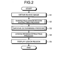
- FIG. 2 is a whole flowchart showing the process performed by the image processing apparatus 5. The process described below is implemented when the units of the image processing apparatus 5 operate in accordance with the image processing program 11a that is stored in the storage unit 11.
- the image obtaining unit 12 first reads image data on an in-vivo image from the attached portable recording medium 4 and obtains the in-vivo image that is taken by the capsule endoscope 2 (Step S1). Then, the suspected-lesion-region extracting unit 16 of the processing unit 13 performs a suspected-lesion-region extracting process, i.e., extracts a suspected concavity lesion region and a suspected convexity lesion region from the in-vivo image that is obtained at Step S1 as suspected lesion regions (Step S2). The groove determining unit 17 performs a groove determining process, i.e., determines whether the suspected concavity lesion region is the groove region (Step S3).
- a suspected-lesion-region extracting process i.e., extracts a suspected concavity lesion region and a suspected convexity lesion region from the in-vivo image that is obtained at Step S1 as suspected lesion regions.
- the groove determining unit 17 performs a groove
- the lesion-region extracting unit 18 performs a lesion-region extracting process, i.e., extracts the lesion region from the suspected concavity lesion regions and the suspected convexity lesion regions using a result of the determination by the groove determining process (Step S4).
- the processing unit 13 displays the lesion region that is extracted at Step S4 on the display unit 15 via the control unit 10 (Step S5), and the process performed by the image processing apparatus 5 ends.
- FIG. 3 is a flowchart showing the suspected-lesion-region extracting process in detail.
- the suspected lesion region is considered to be a section having a pixel value different from those of the surrounding pixels that form healthy tissues.
- the different-pixel extracting unit 16a sets the pixels that form the in-vivo image to a focus pixel sequentially and calculates a pixel-value variation amount using the focus pixel and surrounding pixels that are away from the focus pixel by a predetermine number of pixels ⁇ or a distance equivalent to the number of pixels ⁇ (Step S201).
- the color component corresponding to a blood absorbing band is used to calculate the pixel-value variation amount. If the in-vivo image is an RGB image, a change of the pixel value due to a lesion tends to appear in the G component corresponding to the blood absorbing band. Therefore, in the present embodiment, the RGB image is used and the G component image out of the RGB image is used to calculate the pixel-value variation amount.
- FIG. 4 is a schematic diagram that explains a pixel-value-variation-amount calculating method.
- the pixel-value variation amount for example, four directions with respect to a focus pixel IP are used including the horizontal direction, the vertical direction, the lower-left-and-upper-right direction, and the upper-left-and-lower-right direction. As shown in FIG.
- pixels away from the focus pixel IP in the horizontal direction by the predetermined number of pixels ⁇ or the distance equivalent to the number of pixels ⁇ are assumed to be surrounding pixels IA hor and IB hor ; pixels away from the focus pixel IP in the vertical direction are assumed to be surrounding pixels IA ver and IB ver ; pixels away from the focus pixel IP in the lower-left-and-upper-right direction are assumed to be surrounding pixels IA sla and IB sla ; pixels away from the focus pixel IP in the upper-left-and-lower-right direction are assumed to be surrounding pixels IA bac and IB bac .
- the pixel-value variation amount is calculated using the focus pixel and these pixels.
- a pixel-value variation amount V hor in the horizontal direction with respect to the focus pixel IP is calculated in accordance with the following equation (1) using the focus pixel IP, the surrounding pixels IA hor and IB hor :
- the pixel-value variation amounts V hor , V ver , V sla , and V bac that are calculated in accordance with equations (1) to (4) are collectively referred to as pixel-value variation amount V dir .
- the suffix dir indicates any of the predetermined directions with respect to the focus pixel IP (any of the vertical direction, the horizontal direction, the lower-left-and-upper-right direction, and the upper-left-and-lower-right direction in the present embodiment).
- the pixel-value variation amount V dir is a positive value. In contrast, if a region of the focus pixel IP is depressing more than the surroundings, the pixel-value variation amount V dir is a negative value. This is because, in general, a region protruding more than the surroundings is brighter than the surroundings and has a higher brightness value, while a region depressing more than the surroundings is darker than the surroundings and has a lower brightness value.
- the different-pixel extracting unit 16a extracts a pixel having a pixel value meaningfully different from those of the surrounding pixels as a pixel associated with a suspected lesion using the calculated pixel-value variation amount V dir (Step S202).
- the different-pixel extracting unit 16a determines convexity and concavity in an area of each of the pixels that form the in-vivo image and extracts a pixel that is determined as the suspected convexity lesion region or a pixel that is determined as the suspected concavity lesion region.
- the different-pixel extracting unit 16a determines that the pixel is protruding more than the surroundings and extracts the pixel.
- the different-pixel extracting unit 16a determines that the pixel is depressing more than the surroundings and extracts the pixel.
- the region-data obtaining unit 16b defines a region of the suspected convexity or concavity lesion that is extracted at Step S202 and extracts a region that is possibly the suspected lesion region (Step S203). Specifically, the region-data obtaining unit 16b first creates a convexity binary image, in which the pixel that is protruding more than the surroundings is "1" and the pixel that is no protruding more than the surroundings is "0", and a concavity binary image, in which the pixel that is depressing more than the surroundings is "1" and the pixel that is no depressing more than the surroundings is "0".
- the region-data obtaining unit 16b then performs the well-known labeling process on each of the convexity binary image and the concavity binary image and assigns a unique value (label) to connection components (a group of pixels connected to each other) of the binary images, thereby defining the region.
- label a unique value
- connection components a group of pixels connected to each other
- the region-data obtaining unit 16b determines the convexity to be the convexity that is possibly the suspected lesion region and the concavity to be the concavity that is possibly the suspected lesion region and determines both the convexity and the concavity to be the regions that is possibly the suspected lesion regions.
- the region-data obtaining unit 16b calculates feature data on each of the regions that are possibly the suspected lesion regions that are extracted at Step S203 (Step S204).
- the feature data is expressed by, for example, the average of pixel values within the region (Rabs_m, Gabs_m, B abs_m ), the average of pixel-value variation amounts within the region (R var _ m , G var_m , B var_m ), the area of the region S_ m , the perimeter of the region L _m , the Feret's diameter of the region Fere _m ( ⁇ ), the longer diameter of the region L l_m , the shorter diameter of the region L s_m, the ratio between the longer diameter and the shorter diameter L r_m , the edge strength of the outline of the region E _m , and the degree of circularity of the region C _m . These values are calculated from each of the regions that are possibly the suspected lesion regions.
- the suffix m indicates an average
- the average of pixel values within the region (R abs _ m , G abs_m , B abs_m ) is obtained by calculating a sum of R values, a sum of G values, and a sum of B values of the pixels that are in the same suspected lesion region and then dividing the sums by the area of the region.
- the pixel-value variation amount V dir that is calculated at Step S201 can be used as the pixel-value variation amount of the G component.
- V r V hor + V ver + V sla + V bac 4
- the averages of the directional pixel-value variation amounts V r in the G component of all the pixels in the same suspected lesion region are added, and the calculated sum is divided by the area of the region, whereby the average of the pixel-value variation amounts within the region G var_m is calculated.
- the average of the pixel-value variation amounts within the region can be calculated using the maximum value or the minimum value of the pixel-value variation amounts V dir instead of the average of the directional pixel-value variation amounts.
- the pixel-value variation amount of each direction is calculated using equations (1) to (4) in the same manner as described with reference to FIG. 4 .
- the average of the directional pixel-value variation amounts V r is then calculated in the same manner as in the G component.
- the averages of the directional pixel-value variation amounts of all the pixels in the same suspected lesion region are added and the calculated sum is divided by the area of the region, whereby the averages of the pixel-value variation amounts within the region R var_m and B var_m are calculated.
- the area of the region S_ m is calculated on each suspected lesion region by counting the number of pixels that are in the same suspected lesion region.
- the perimeter of the region L_ m is calculated on each suspected lesion region by counting the number of pixels that are positioned on the outline of the region from among the pixels that are in the same suspected lesion region. Specifically, a pixel from among the pixels that form the in-vivo image is assumed to be a focus pixel and whether the focus pixel is an outline pixel is determined. The pixels that form the in-vivo image are set to the focus pixel sequentially.
- FIG. 5 is a schematic diagram that explains how to determine the outline pixel. As shown in FIG. 5 , four pixels P 1 to P 4 that are adjacent to the focus pixel IP are assumed to be the surrounding pixels.
- the focus pixel IP is determined to be an outline pixel. The number of the outline pixels that are determined in this manner is counted on each suspected lesion region.
- FIG. 6 is a schematic diagram that explains how to calculate the Feret's diameter Fere _m ( ⁇ 1 ) of a suspected lesion region 19.
- two lines 21a and 21b tangent to the suspected lesion region 19 are obtained in such a manner that an angle between the tangent line 21a and a horizontal line 20a and an angle between the tangent line 21b and a horizontal line 20b are set to ⁇ 1 and the distance between the tangent lines 21a and 21b are set as long as possible.
- a distance 22 between the two tangent lines is the Feret's diameter Fere _m ( ⁇ 1 ) of the suspected lesion region 19 at the angle ⁇ 1 .
- the Feret's diameter of the target suspected lesion region is calculated at each angle ⁇ .
- the maximum Feret's diameter of the calculated Feret's diameters is the longer diameter of the region L l_m .
- the minimum Feret's diameter of the calculated Feret's diameters is the shorter diameter of the region L s_m .
- the value of the intercept b ⁇ 1 (j) is calculated using the following equation (8) where (x j , y j ) is the position of the j-th outline pixel of the target suspected lesion region.
- the pixel position (x j , y j ) of the outline pixel is used in equation (8).
- the longer diameter L l_m which is the maximum Feret's diameter of the Feret's diameters Fere _m ( ⁇ i ) of the target suspected lesion region that are calculated by increment of the angle ⁇ i
- the shorter diameter L s_m which is the minimum Feret's diameter
- L r_m L l_m L s_m
- the edge strength of the outline of the region E_ m is calculated by applying an edge detecting filter shown in FIG. 7-1 or FIG. 7-2 to a grayscale image that represents either any of the R component, the G component, and the B component of the in-vivo image or an average of the R, the G, and the B components.
- An edge strength image E 1 (i) that is created using a sobel (Sobel) filter, which is the first deviation, is expressed by the following equation (15) using an output S1(i) that is a convolution of a sobel filter SF1 in the horizontal direction (x direction) shown in FIG. 7-1 and an output S2(i) that is a convolution of a sobel filter SF2 in the vertical direction (y direction) shown in FIG. 7-2 in which i indicates the pixel position in the image:
- E 1 i S ⁇ 1 ⁇ i 2 + S ⁇ 2 ⁇ i 2
- the regional-feature-data determining unit 16c refines suspected lesion regions by excluding concavities having feature data that indicates something other than lesions from the concavities that are possibly the suspected lesion regions (Step S205) as shown in FIG. 3 . Specifically, the regional-feature-data determining unit 16c determines whether each concavity that is possibly the suspected lesion region is a lesion or a non-lesion by comparing the feature data with a distribution of feature data on teacher data.
- the average of pixel values within the region is used as a feature-data parameter x to determine whether the target concavity is a lesion or a non-lesion
- the following process is performed in advance.
- Sample regions that represent various medical conditions, such as bleeding, are collected as teacher data.
- the sample regions are categorized into some lesion groups on the medical-condition basis.
- a pixel-value average ⁇ k and a pixel-value covariance ⁇ k of each of the lesion groups are calculated, in which k indicates the group number of the lesion group. Samples are collected even from the concavities that are not the suspected lesion regions.
- samples are categorized into non-lesion groups in such a manner that some having the same factor because of which they are extracted as the concavities or some having the pixel-value averages closer to each other are categorized to the same non-lesion group.
- a pixel-value average ⁇ i and a pixel-value covariance ⁇ i of each of the non-lesion groups are calculated, in which i indicates the group number of the non-lesion group.
- a probability that the target concavity to be compared is generated from a distribution of a lesion group is calculated using the following equation (18) where the distribution of each of the lesion groups is assumed to be a normal distribution, and a probability that the target concavity is generated from a distribution of a non-lesion group is calculated using the following equation (19) where the distribution of each of the non-lesion groups is assumed to be a normal distribution: p k
- x 1 2 ⁇ ⁇ n / 2
- x 1 2 ⁇ ⁇ n / 2
- the sum of the probabilities that the target concavity is generated from a distribution of a lesion group is expressed by ⁇ p(k
- the probability that the target concavity belongs to a certain medical condition is calculated on each medical condition using equation (20).
- x). If this value is equal to or lower than a predetermined threshold LesionProbTh, i.e., p(k a max
- the regional-feature-data determining unit 16c performs the processing on the convexities that are possibly the suspected lesion regions in the same manner as it determines at Step S205 whether the concavity is a lesion or a non-lesion and excludes the convexity having the feature data that indicates something other than lesions, thereby refining the suspected lesion regions (Step S206).
- the process control returns to Step S2 of FIG. 2 . That is, it calculates the probability, which is generated from a distribution of a group of the prepared teacher data, and determines whether the target region is a lesion or a non-lesion.
- the convexities that are generated due to a factor other than a lesion are excluded from the convexities that are possibly the suspected lesion regions.
- the remaining convexities are extracted as the suspected convexity lesion regions.
- the feature-data parameter that is used to determine whether the target region is the region that is possibly the suspected lesion region is not limited to the average of pixel values within the region (R abs_m , G abs_m , B abs_m ). Some other values, such as the area of the region S _m , the perimeter of the region L_ m , the Feret's diameter of the region Fere _m ( ⁇ ), the longer diameter of the region L l_m , the shorter diameter of the region L s_m , the ratio between the longer diameter and the shorter diameter L r_m , the edge strength of the outline of region E_ m , and the degree of circularity of the region C _m can be used. Moreover, it is allowable to combine these values appropriately.
- the process at Step S206 using the convexities can be performed prior to the process at Step S205 using the concavities, or these processes can be performed in parallel.
- FIG. 8 is a flowchart showing the groove determining process in detail.
- each of the suspected concavity lesion regions is subjected to a set of processes indicated by a loop A (Steps S301 to S307).
- the reason why the suspected concavity lesion regions are in focus is that a part corresponding to a groove that is formed between in-vivo organ walls is included in regions that are depressing more than the surroundings.
- the suspected concavity lesion region to be processed is referred to as a focus concavity.
- the surrounding-similar-pixel extracting unit 17a first extracts a pixel having a pixel value that is close to those of the pixels that form the focus concavity from pixels surrounding the focus concavity (Step S302). Specifically, the surrounding-similar-pixel extracting unit 17a first defines a surrounding pixel area that is a predetermined area surrounding the focus concavity.
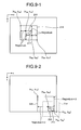
- FIGS. 9-1 and 9-2 are schematic diagrams that explain how to define the surrounding pixel area.
- the surrounding pixel area is defined by calculating, using a start coordinate point (x RS , y RS ) and an end coordinate point (x RE , y RE ) of a bounding rectangle Z13 of a focus concavity Z11, a start coordinate point (x PS , y PS ) and an end coordinate point (x PE , y PE ) of a rectangular region Z15 that is obtained by extending the bounding rectangle Z13 using an extension value RegionLen.
- the extension value RegionLen depends on a size of the focus concavity as is clear from, for example, the following equation (21). As shown in FIG.
- the surrounding pixel area is defined in the following manner.
- the extension value RegionLen that is a value by which the region is extended in a direction opposite to a direction in which it is outside the image area is set, for example, double.
- the area Z24 indicated by the dotted lines is outside the side of the image area running toward right in FIG. 9-2 along the x axis and the side of the image area running toward the bottom in FIG.
- the surrounding pixel area is defined by calculating the start coordinate point (x PS , y PS ) and the end coordinate point (x PE , y PE ) of the rectangular region Z25 that is obtained by extending by RegionLen ⁇ 2 in both the leftward direction in FIG. 9-2 along the negative x axis and the upward direction in FIG. 9-2 along the negative y axis.
- the surrounding pixel area is calculated and defined using the following equations (21) to (25) using the start coordinate point (x RS , y RS ) and the end coordinate point (x RE , y RE ) of the bounding rectangle of the focus concavity.
- ImgSizeX is a size of the in-vivo image in the x coordinate.
- ImgSizeY is a size of the in-vivo image in the y coordinate.
- RegionLen x RE - x RS 2 + y RE - y RS 2
- x PS ⁇ x RS - Re ⁇ gionLen If x PE ⁇ ImgSizeX is calculated using Equation 24 x RS - Re ⁇ gionLen ⁇ 2 If x PE ⁇ ImgSizeX is calculated using Equation 24 If x PS ⁇ 0, x PS is set to 0 after evaluated using Equation (24).
- y PS ⁇ y RS - Re ⁇ gionLen If y PE ⁇ ImgSize ⁇ Y is calculated using Equation 25 y RS - Re ⁇ gionLen ⁇ 2 If y PE ⁇ ImgSize ⁇ Y is calculated using Equation 25 If y PS ⁇ 0, y PS is set to 0 after evaluated using Equation (25).
- x PE ⁇ x RE + Re ⁇ gionLen If x PS ⁇ 0 is calculated using Equation 22 x RE + Re ⁇ gionLen ⁇ 2 If x PS ⁇ 0 is calculated using Equation 22 If x PE ⁇ ImgSizeX, x PE is set to lmgSizeX - 1 after evaluated using Equation (22).
- y PE ⁇ y RE + Re ⁇ gionLen If y PS ⁇ 0 is calculated using Equation 23 y RE + Re ⁇ gionLen ⁇ 2 If y PS ⁇ 0 is calculated using Equation 23 If Y PE ⁇ ImgSizeY, Y PE is set to ImgSizeY - 1 after evaluated using Equation (23).
- the method of setting the surrounding pixel area is not limited to the setting method using the start point (X RS , y RS ) and the end coordinate point (x RE , y RE ) of the bounding rectangle of the focus concavity.
- Some other values such as a length of the diagonal of the bounding rectangle of the focus concavity, the area, the Feret's diameter, the longer diameter, and the shorter diameter of the focus concavity, can be used.
- This determination is made using at least one of the brightness, the chromaticity, and the color difference of the pixel containing the G component.
- the G component which is corresponding to the blood bleeding band and is sensible enough to show a difference between the healthy region and the lesion region in the form of the pixel value. SimilarGValTh, SimilarG_RValTh, and SimilarGBValTh are predetermined thresholds.
- R abs_m is an average of the R components within the region of the focus concavity
- G abs_m is the G components within the region of the focus concavity
- B abs_m is the B components within the region of the focus concavity.
- the extended-groove-region creating unit 17b creates a groove-direction extended region (Step S303) and calculates shape feature data of the created groove-direction extended region (Step S304). Specifically, the extended-groove-region creating unit 17b performs well-know region definition process using particle analysis by using both the pixels that contribute the focus concavity and the pixels that are extracted from the surrounding pixel area at Step S302 because they have pixel values close to those of the focus concavity and sets the obtained region to be the groove-direction extended region. The extended-groove-region creating unit 17b calculates the shape feature data of the groove-direction extended region using the particle analysis. The extended-groove-region creating unit 17b calculates, for example, an area ES _m of the obtained groove-direction extended region as the shape feature data.
- the extended-groove-region creating unit 17b calculates a ratio RS _m between the area S_ m of the focus concavity and the area ES _m of the groove-direction extended region using the following equation (29) as a shape feature-data variation amount between the focus concavity and the groove-direction extended region that is created based on the focus concavity (Step S305).
- RS _m ES _m S _m
- the shape feature data that is calculated at Step S304 is not limited to the area of the groove-direction extended region. Some other values, such as the perimeter of the region, the Feret's diameter, the longer diameter of the region, the shorter diameter of the region, the ratio between the longer diameter and the shorter diameter, can be calculated.
- the shape feature-data variation amount that is calculated at Step S305 is not limited to the ratio between the area of the focus concavity and the area of the groove-direction extended region. Some other values, such as the difference in the perimeter of the region, the difference in the Feret's diameter of the region, the difference between the longer diameter and the shorter diameter of the region, and the difference in the ratio between the longer diameter and the shorter diameter of the region, can be calculated in accordance with the shape feature data.
- the extended-groove-region creating unit 17b determines that the focus concavity is the groove region (Step S306): RS _m > SurroundAreaDifTh where SurroundAreaDifTh is a predetermined threshold.
- Step S3 of FIG. 2 After each of the suspected lesion regions has been subjected to the processes of the loop A as the focus concavity, the process control returns to Step S3 of FIG. 2 .
- the lesion-region extracting unit 18 excludes the suspected concavity lesion region that is determined to be the groove region in the groove determining process from the suspected lesion regions and extracts the remaining suspected concavity regions and the suspected convexity regions that are extracted at Step S206 as the lesion regions.
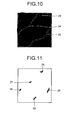
- FIG. 10 is a display example of an original in-vivo image.
- the in-vivo image shown in FIG. 10 includes a bleeding section 23 and grooves 24 and 25 that are formed between organ walls.
- FIG. 11 is an example of an extracted concavity image that represents the suspected concavity region that is extracted from the in-vivo image shown in FIG. 10 .
- a plurality of suspected concavity lesion regions 26 to 30 having the substantially same area that is extracted through the suspected-lesion-region extracting process is shown.
- FIG. 12 is an example of the groove-direction extended region that is created from each of the suspected concavity lesion regions 26 to 30 shown in the extracted concavity image of FIG. 11 .
- the suspected concavity lesion regions 27 and 28 which are associated with the groove 24 that is formed between the organ walls (see FIG. 10 ), are extended in the direction in which the pixels that form the groove 24 are arranged and converted to groove-direction extended regions 32 and 33, respectively.
- the suspected concavity lesion regions 29 and 30 which are associated with the groove 25 that is formed between the organ walls (see FIG.
- the created groove-direction extended region is extended in the groove direction from the original extracted concavity image.
- the suspected concavity lesion region 26 that is associated with the bleeding section 23 is converted to a groove-direction extended region 31 shown in FIG. 12 as a result of creation of the groove-direction extended region.
- a change from the suspected concavity lesion region 26 to the groove-direction extended region 31 is not large.
- the pixel value such as the brightness, the color ratio, and the color difference, changes drastically when it comes from the surrounding area to the lesion region.
- the probability that a pixel having a close pixel value is present in the surrounding area is low. Therefore, a change from the original extracted concavity image to the created groove-direction extended region is small.
- the lesion-region extracting unit 18 determines, while assuming that the suspected concavity lesion regions 27, 28, 29, and 30 shown in FIG. 11 that are extended by the process performed by the groove determining unit 17 in the direction in which the pixels that form the groove to be the groove regions, the suspected concavity lesion region 26, which is not extended largely, to be the lesion region and finally extracts the suspected concavity lesion region 26 as the lesion region.
- a lesion region 36 is displayed as an extracted lesion image in a recognizable manner on the display unit 15 at Step S5 of FIG. 2 as shown in FIG. 13 , for example.
- the display manner is not limited to the manner shown in FIG. 13 in which the extracted lesion region in a color different from a color of the background is displayed on a background image (in, for example, black color) having the same size as the original in-vivo image.
- a background image in, for example, black color
- it is allowable to display this extracted lesion image overlapped with the in-vivo image.
- it is allowable to display the outline of the lesion region on the in-vivo image so that the lesion region within the in-vivo image can be identified.
- the accuracy in detecting a lesion region is maintained high, regardless of change of the pixel value due to, for example, how grooves and part other than the grooves are exposed to an illumination light. Therefore, an image processing apparatus that is stable against difference in an in-vivo image taking environment can detect the lesion region with a high accuracy.
- the image processing apparatus, the image processing program, and the image processing method according to the present invention are suitable for processing in-vivo images that are obtained by taking an image of an in-vivo cavity.
Landscapes
- Engineering & Computer Science (AREA)
- Health & Medical Sciences (AREA)
- Physics & Mathematics (AREA)
- Life Sciences & Earth Sciences (AREA)
- Theoretical Computer Science (AREA)
- General Physics & Mathematics (AREA)
- Computer Vision & Pattern Recognition (AREA)
- Medical Informatics (AREA)
- Nuclear Medicine, Radiotherapy & Molecular Imaging (AREA)
- Radiology & Medical Imaging (AREA)
- Surgery (AREA)
- General Health & Medical Sciences (AREA)
- Optics & Photonics (AREA)
- Biophysics (AREA)
- Molecular Biology (AREA)
- Animal Behavior & Ethology (AREA)
- Biomedical Technology (AREA)
- Public Health (AREA)
- Veterinary Medicine (AREA)
- Quality & Reliability (AREA)
- Pathology (AREA)
- Heart & Thoracic Surgery (AREA)
- Signal Processing (AREA)
- Endoscopes (AREA)
- Measurement Of The Respiration, Hearing Ability, Form, And Blood Characteristics Of Living Organisms (AREA)
- Image Processing (AREA)
- Image Analysis (AREA)
- Apparatus For Radiation Diagnosis (AREA)
- Magnetic Resonance Imaging Apparatus (AREA)
- Ultra Sonic Daignosis Equipment (AREA)
Applications Claiming Priority (2)
| Application Number | Priority Date | Filing Date | Title |
|---|---|---|---|
| JP2007158027A JP5106928B2 (ja) | 2007-06-14 | 2007-06-14 | 画像処理装置および画像処理プログラム |
| PCT/JP2008/059997 WO2008152924A1 (ja) | 2007-06-14 | 2008-05-30 | 画像処理装置、画像処理プログラムおよび画像処理方法 |
Publications (3)
| Publication Number | Publication Date |
|---|---|
| EP2156782A1 true EP2156782A1 (de) | 2010-02-24 |
| EP2156782A4 EP2156782A4 (de) | 2012-05-09 |
| EP2156782B1 EP2156782B1 (de) | 2015-07-01 |
Family
ID=40129534
Family Applications (1)
| Application Number | Title | Priority Date | Filing Date |
|---|---|---|---|
| EP08764915.8A Not-in-force EP2156782B1 (de) | 2007-06-14 | 2008-05-30 | Bildverarbeitungsvorrichtung, bildverarbeitungsprogramm und bildverarbeitungsverfahren |
Country Status (4)
| Country | Link |
|---|---|
| US (1) | US8989459B2 (de) |
| EP (1) | EP2156782B1 (de) |
| JP (1) | JP5106928B2 (de) |
| WO (1) | WO2008152924A1 (de) |
Cited By (2)
| Publication number | Priority date | Publication date | Assignee | Title |
|---|---|---|---|---|
| US8509509B2 (en) | 2010-06-30 | 2013-08-13 | Olympus Medical Systems Corp. | Image processing apparatus and image processing method |
| US9715727B2 (en) | 2012-02-23 | 2017-07-25 | Smith & Nephew, Inc. | Video endoscopic system |
Families Citing this family (29)
| Publication number | Priority date | Publication date | Assignee | Title |
|---|---|---|---|---|
| JP4493679B2 (ja) * | 2007-03-29 | 2010-06-30 | 富士フイルム株式会社 | 対象領域抽出方法および装置ならびにプログラム |
| WO2008139812A1 (ja) * | 2007-05-08 | 2008-11-20 | Olympus Corporation | 画像処理装置および画像処理プログラム |
| US9396308B1 (en) * | 2009-04-22 | 2016-07-19 | Humana Inc. | Physiological imagery generator system and method |
| JP5455550B2 (ja) * | 2009-10-23 | 2014-03-26 | Hoya株式会社 | 電子内視鏡用プロセッサ |
| US9483622B1 (en) | 2010-01-11 | 2016-11-01 | Humana Inc. | Pain visualization system and method |
| US20110173947A1 (en) * | 2010-01-19 | 2011-07-21 | General Electric Company | System and method for gas turbine power augmentation |
| JP5011452B2 (ja) * | 2010-04-12 | 2012-08-29 | オリンパスメディカルシステムズ株式会社 | 医用画像処理装置および医用画像処理装置の制御方法 |
| JP5570866B2 (ja) * | 2010-04-30 | 2014-08-13 | オリンパス株式会社 | 画像処理装置、画像処理装置の作動方法、および画像処理プログラム |
| JPWO2011161993A1 (ja) * | 2010-06-24 | 2013-08-19 | オリンパスメディカルシステムズ株式会社 | 画像処理装置及び画像処理装置の制御方法 |
| JP5658945B2 (ja) * | 2010-08-24 | 2015-01-28 | オリンパス株式会社 | 画像処理装置、画像処理装置の作動方法、および画像処理プログラム |
| JP5620194B2 (ja) * | 2010-08-24 | 2014-11-05 | オリンパス株式会社 | 画像処理装置、画像処理方法、および画像処理プログラム |
| JP5555097B2 (ja) * | 2010-08-24 | 2014-07-23 | オリンパス株式会社 | 画像処理装置、画像処理装置の作動方法、および画像処理プログラム |
| WO2012105141A1 (ja) * | 2011-02-01 | 2012-08-09 | オリンパスメディカルシステムズ株式会社 | 診断支援装置 |
| CN103458765B (zh) * | 2011-07-12 | 2016-02-10 | 奥林巴斯株式会社 | 图像处理装置 |
| JP5800626B2 (ja) * | 2011-07-29 | 2015-10-28 | オリンパス株式会社 | 画像処理装置、画像処理方法、及び画像処理プログラム |
| JP5959168B2 (ja) | 2011-08-31 | 2016-08-02 | オリンパス株式会社 | 画像処理装置、画像処理装置の作動方法、及び画像処理プログラム |
| WO2013061939A1 (ja) * | 2011-10-26 | 2013-05-02 | オリンパス株式会社 | 内視鏡装置及びフォーカス制御方法 |
| JP5926937B2 (ja) * | 2011-11-30 | 2016-05-25 | オリンパス株式会社 | 画像処理装置、画像処理方法、及び画像処理プログラム |
| JP6027803B2 (ja) * | 2012-07-17 | 2016-11-16 | Hoya株式会社 | 画像処理装置及び内視鏡装置 |
| JP5857227B2 (ja) * | 2012-11-09 | 2016-02-10 | パナソニックIpマネジメント株式会社 | 画像処理装置および内視鏡 |
| WO2014156937A1 (ja) * | 2013-03-27 | 2014-10-02 | 富士フイルム株式会社 | 画像処理装置及び内視鏡システムの作動方法 |
| JP6113387B1 (ja) | 2015-08-13 | 2017-04-12 | Hoya株式会社 | 評価値計算装置及び電子内視鏡システム |
| WO2017026539A1 (ja) | 2015-08-13 | 2017-02-16 | Hoya株式会社 | 評価値計算装置及び電子内視鏡システム |
| EP3677168A4 (de) * | 2017-08-31 | 2020-11-04 | Osaka University | Pathologisches diagnosegerät, bildverarbeitungsverfahren und programm |
| US11457795B2 (en) | 2017-11-06 | 2022-10-04 | Hoya Corporation | Processor for electronic endoscope and electronic endoscope system |
| JP7084994B2 (ja) * | 2018-07-06 | 2022-06-15 | オリンパス株式会社 | 内視鏡用画像処理装置、及び、内視鏡用画像処理装置の作動方法、並びに、内視鏡用画像処理プログラム |
| US12029385B2 (en) * | 2018-09-27 | 2024-07-09 | Hoya Corporation | Electronic endoscope system |
| CN117372439B (zh) * | 2023-12-08 | 2024-03-12 | 天津市肿瘤医院(天津医科大学肿瘤医院) | 一种基于核磁和ct融合的子宫病变位置识别方法、系统及介质 |
| CN118787301B (zh) * | 2024-09-10 | 2024-11-26 | 大连清东科技有限公司 | 一种用于呼吸道传染病的气管镜辅助导航方法 |
Family Cites Families (20)
| Publication number | Priority date | Publication date | Assignee | Title |
|---|---|---|---|---|
| US5057682A (en) * | 1989-12-26 | 1991-10-15 | General Electric Company | Quiescent signal compensated photodetector system for large dynamic range and high linearity |
| JP3142079B2 (ja) * | 1992-03-19 | 2001-03-07 | 株式会社日立製作所 | 光ct装置 |
| US5694933A (en) * | 1995-04-28 | 1997-12-09 | Care Wise Medical Products Corporation | Apparatus and methods for determining spatial coordinates of radiolabelled tissue using gamma-rays and associated characteristic X-rays |
| JP4393016B2 (ja) * | 2000-06-30 | 2010-01-06 | 株式会社日立メディコ | 画像診断支援装置 |
| US7245754B2 (en) * | 2000-06-30 | 2007-07-17 | Hitachi Medical Corporation | image diagnosis supporting device |
| WO2002056240A1 (en) * | 2000-11-22 | 2002-07-18 | R2 Technology, Inc. | Graphical user interface for display of anatomical information |
| JP4450973B2 (ja) * | 2000-11-30 | 2010-04-14 | オリンパス株式会社 | 診断支援装置 |
| ATE509328T1 (de) | 2001-03-14 | 2011-05-15 | Given Imaging Ltd | Verfahren und system zum erkennen colorimetrischer anomalien |
| AU2003216295A1 (en) * | 2002-02-15 | 2003-09-09 | The Regents Of The University Of Michigan | Lung nodule detection and classification |
| US7355597B2 (en) * | 2002-05-06 | 2008-04-08 | Brown University Research Foundation | Method, apparatus and computer program product for the interactive rendering of multivalued volume data with layered complementary values |
| JP4336083B2 (ja) * | 2002-06-20 | 2009-09-30 | 株式会社日立メディコ | 画像診断支援装置、画像診断支援方法 |
| US6937776B2 (en) * | 2003-01-31 | 2005-08-30 | University Of Chicago | Method, system, and computer program product for computer-aided detection of nodules with three dimensional shape enhancement filters |
| WO2004081865A2 (en) * | 2003-03-10 | 2004-09-23 | University Of Iowa Research Foundation | Systems and methods for bioliminescent computed tomographic reconstruction |
| US7483023B2 (en) * | 2005-03-17 | 2009-01-27 | Siemens Medical Solutions Usa, Inc. | Model based adaptive multi-elliptical approach: a one click 3D segmentation approach |
| EP1870020B1 (de) * | 2005-04-13 | 2015-08-05 | Olympus Medical Systems Corp. | Bildverarbeitungsapparat und bildverarbeitungsverfahren |
| JP4855709B2 (ja) * | 2005-04-27 | 2012-01-18 | オリンパスメディカルシステムズ株式会社 | 画像処理装置、画像処理方法、及び画像処理プログラム |
| KR100943367B1 (ko) * | 2005-04-27 | 2010-02-18 | 올림푸스 메디칼 시스템즈 가부시키가이샤 | 화상 처리 장치, 화상 처리 방법, 및 화상 처리 프로그램을 기록한 기록 매체 |
| US7689016B2 (en) * | 2005-05-27 | 2010-03-30 | Stoecker & Associates, A Subsidiary Of The Dermatology Center, Llc | Automatic detection of critical dermoscopy features for malignant melanoma diagnosis |
| US8600125B2 (en) * | 2005-06-22 | 2013-12-03 | The Research Foundation Of State University Of New York | System and method for computer aided polyp detection |
| US8111896B2 (en) * | 2006-05-15 | 2012-02-07 | Im3D S.P.A. | Method and system for automatic recognition of preneoplastic anomalies in anatomic structures based on an improved region-growing segmentation, and commputer program therefor |
-
2007
- 2007-06-14 JP JP2007158027A patent/JP5106928B2/ja not_active Expired - Fee Related
-
2008
- 2008-05-30 EP EP08764915.8A patent/EP2156782B1/de not_active Not-in-force
- 2008-05-30 WO PCT/JP2008/059997 patent/WO2008152924A1/ja not_active Ceased
-
2009
- 2009-12-14 US US12/637,162 patent/US8989459B2/en active Active
Cited By (3)
| Publication number | Priority date | Publication date | Assignee | Title |
|---|---|---|---|---|
| US8509509B2 (en) | 2010-06-30 | 2013-08-13 | Olympus Medical Systems Corp. | Image processing apparatus and image processing method |
| US9715727B2 (en) | 2012-02-23 | 2017-07-25 | Smith & Nephew, Inc. | Video endoscopic system |
| US10783626B2 (en) | 2012-02-23 | 2020-09-22 | Smith & Nephew, Inc. | Video endoscopic system |
Also Published As
| Publication number | Publication date |
|---|---|
| US8989459B2 (en) | 2015-03-24 |
| EP2156782A4 (de) | 2012-05-09 |
| EP2156782B1 (de) | 2015-07-01 |
| JP5106928B2 (ja) | 2012-12-26 |
| WO2008152924A1 (ja) | 2008-12-18 |
| JP2008307229A (ja) | 2008-12-25 |
| US20100092055A1 (en) | 2010-04-15 |
Similar Documents
| Publication | Publication Date | Title |
|---|---|---|
| EP2156782B1 (de) | Bildverarbeitungsvorrichtung, bildverarbeitungsprogramm und bildverarbeitungsverfahren | |
| EP1994878B9 (de) | Vorrichtung und verfahren zur bearbeitung medizinischer bilder | |
| JP5276225B2 (ja) | 医用画像処理装置及び医用画像処理装置の作動方法 | |
| JP5800468B2 (ja) | 画像処理装置、画像処理方法、および画像処理プログラム | |
| US10194783B2 (en) | Image processing apparatus, image processing method, and computer-readable recording medium for determining abnormal region based on extension information indicating state of blood vessel region extending in neighborhood of candidate region | |
| US9672610B2 (en) | Image processing apparatus, image processing method, and computer-readable recording medium | |
| EP2859833A1 (de) | Bildverarbeitungsvorrichtung, bildverarbeitungsverfahren und bildverarbeitungsprogramm | |
| CN102436638B (zh) | 图像处理装置以及图像处理方法 | |
| EP2294964A1 (de) | Bildbearbeitungsgerät, bildbearbeitungsprogramm und bildbearbeitungsverfahren | |
| EP2163183A1 (de) | Bildaufbereitungsvorrichtung, bildaufbereitungsprogramm und bildaufbereitungsverfahren | |
| US8204287B2 (en) | Image processing apparatus, image processing method and image processing program | |
| EP2502546B1 (de) | Vorrichtung zur verarbeitung medizinischer bilder und verfahren zur verarbeitung medizinischer bilder | |
| EP2233062A1 (de) | Vorrichtung und programm zur erkennung von szenenänderungen | |
| WO2008044466A1 (fr) | Dispositif, procédé et programme de traitement d'image | |
| EP2912988A1 (de) | Vorrichtung zur verarbeitung medizinischer bilder und verfahren zur verarbeitung medizinischer bilder | |
| EP2502547B1 (de) | Bildverarbeitungsvorrichtung und bildverarbeitungsverfahren | |
| EP1994877A1 (de) | Medizinische bildverarbeitungsvorrichtung und medizinisches bildverarbeitungsverfahren | |
| JP2006166990A (ja) | 医用画像処理方法 | |
| CN103561631A (zh) | 图像处理装置和图像处理方法 | |
| Suman et al. | Detection and classification of bleeding using statistical color features for wireless capsule endoscopy images | |
| KR20220007667A (ko) | 화상 해석 장치 및 화상 해석 방법 | |
| JP4856275B2 (ja) | 医用画像処理装置 | |
| JP2011120731A (ja) | 内視鏡装置 |
Legal Events
| Date | Code | Title | Description |
|---|---|---|---|
| PUAI | Public reference made under article 153(3) epc to a published international application that has entered the european phase |
Free format text: ORIGINAL CODE: 0009012 |
|
| 17P | Request for examination filed |
Effective date: 20091211 |
|
| AK | Designated contracting states |
Kind code of ref document: A1 Designated state(s): AT BE BG CH CY CZ DE DK EE ES FI FR GB GR HR HU IE IS IT LI LT LU LV MC MT NL NO PL PT RO SE SI SK TR |
|
| AX | Request for extension of the european patent |
Extension state: AL BA MK RS |
|
| DAX | Request for extension of the european patent (deleted) | ||
| A4 | Supplementary search report drawn up and despatched |
Effective date: 20120412 |
|
| RIC1 | Information provided on ipc code assigned before grant |
Ipc: A61B 5/07 20060101ALI20120405BHEP Ipc: A61B 1/04 20060101ALI20120405BHEP Ipc: G06T 7/00 20060101AFI20120405BHEP |
|
| REG | Reference to a national code |
Ref country code: DE Ref legal event code: R079 Ref document number: 602008038797 Country of ref document: DE Free format text: PREVIOUS MAIN CLASS: A61B0001000000 Ipc: G06T0007000000 |
|
| GRAP | Despatch of communication of intention to grant a patent |
Free format text: ORIGINAL CODE: EPIDOSNIGR1 |
|
| RIC1 | Information provided on ipc code assigned before grant |
Ipc: A61B 1/04 20060101ALI20141017BHEP Ipc: G06T 7/00 20060101AFI20141017BHEP Ipc: A61B 5/07 20060101ALI20141017BHEP |
|
| INTG | Intention to grant announced |
Effective date: 20141120 |
|
| GRAP | Despatch of communication of intention to grant a patent |
Free format text: ORIGINAL CODE: EPIDOSNIGR1 |
|
| GRAJ | Information related to disapproval of communication of intention to grant by the applicant or resumption of examination proceedings by the epo deleted |
Free format text: ORIGINAL CODE: EPIDOSDIGR1 |
|
| GRAP | Despatch of communication of intention to grant a patent |
Free format text: ORIGINAL CODE: EPIDOSNIGR1 |
|
| INTG | Intention to grant announced |
Effective date: 20150105 |
|
| INTG | Intention to grant announced |
Effective date: 20150115 |
|
| GRAS | Grant fee paid |
Free format text: ORIGINAL CODE: EPIDOSNIGR3 |
|
| GRAA | (expected) grant |
Free format text: ORIGINAL CODE: 0009210 |
|
| AK | Designated contracting states |
Kind code of ref document: B1 Designated state(s): AT BE BG CH CY CZ DE DK EE ES FI FR GB GR HR HU IE IS IT LI LT LU LV MC MT NL NO PL PT RO SE SI SK TR |
|
| REG | Reference to a national code |
Ref country code: GB Ref legal event code: FG4D |
|
| REG | Reference to a national code |
Ref country code: AT Ref legal event code: REF Ref document number: 734355 Country of ref document: AT Kind code of ref document: T Effective date: 20150715 Ref country code: CH Ref legal event code: EP |
|
| REG | Reference to a national code |
Ref country code: IE Ref legal event code: FG4D |
|
| REG | Reference to a national code |
Ref country code: DE Ref legal event code: R096 Ref document number: 602008038797 Country of ref document: DE |
|
| REG | Reference to a national code |
Ref country code: AT Ref legal event code: MK05 Ref document number: 734355 Country of ref document: AT Kind code of ref document: T Effective date: 20150701 |
|
| REG | Reference to a national code |
Ref country code: NL Ref legal event code: MP Effective date: 20150701 |
|
| REG | Reference to a national code |
Ref country code: LT Ref legal event code: MG4D |
|
| PG25 | Lapsed in a contracting state [announced via postgrant information from national office to epo] |
Ref country code: LT Free format text: LAPSE BECAUSE OF FAILURE TO SUBMIT A TRANSLATION OF THE DESCRIPTION OR TO PAY THE FEE WITHIN THE PRESCRIBED TIME-LIMIT Effective date: 20150701 Ref country code: LV Free format text: LAPSE BECAUSE OF FAILURE TO SUBMIT A TRANSLATION OF THE DESCRIPTION OR TO PAY THE FEE WITHIN THE PRESCRIBED TIME-LIMIT Effective date: 20150701 Ref country code: NO Free format text: LAPSE BECAUSE OF FAILURE TO SUBMIT A TRANSLATION OF THE DESCRIPTION OR TO PAY THE FEE WITHIN THE PRESCRIBED TIME-LIMIT Effective date: 20151001 Ref country code: FI Free format text: LAPSE BECAUSE OF FAILURE TO SUBMIT A TRANSLATION OF THE DESCRIPTION OR TO PAY THE FEE WITHIN THE PRESCRIBED TIME-LIMIT Effective date: 20150701 Ref country code: GR Free format text: LAPSE BECAUSE OF FAILURE TO SUBMIT A TRANSLATION OF THE DESCRIPTION OR TO PAY THE FEE WITHIN THE PRESCRIBED TIME-LIMIT Effective date: 20151002 |
|
| PG25 | Lapsed in a contracting state [announced via postgrant information from national office to epo] |
Ref country code: AT Free format text: LAPSE BECAUSE OF FAILURE TO SUBMIT A TRANSLATION OF THE DESCRIPTION OR TO PAY THE FEE WITHIN THE PRESCRIBED TIME-LIMIT Effective date: 20150701 Ref country code: IS Free format text: LAPSE BECAUSE OF FAILURE TO SUBMIT A TRANSLATION OF THE DESCRIPTION OR TO PAY THE FEE WITHIN THE PRESCRIBED TIME-LIMIT Effective date: 20151101 Ref country code: PT Free format text: LAPSE BECAUSE OF FAILURE TO SUBMIT A TRANSLATION OF THE DESCRIPTION OR TO PAY THE FEE WITHIN THE PRESCRIBED TIME-LIMIT Effective date: 20151102 Ref country code: HR Free format text: LAPSE BECAUSE OF FAILURE TO SUBMIT A TRANSLATION OF THE DESCRIPTION OR TO PAY THE FEE WITHIN THE PRESCRIBED TIME-LIMIT Effective date: 20150701 Ref country code: SE Free format text: LAPSE BECAUSE OF FAILURE TO SUBMIT A TRANSLATION OF THE DESCRIPTION OR TO PAY THE FEE WITHIN THE PRESCRIBED TIME-LIMIT Effective date: 20150701 Ref country code: PL Free format text: LAPSE BECAUSE OF FAILURE TO SUBMIT A TRANSLATION OF THE DESCRIPTION OR TO PAY THE FEE WITHIN THE PRESCRIBED TIME-LIMIT Effective date: 20150701 Ref country code: ES Free format text: LAPSE BECAUSE OF FAILURE TO SUBMIT A TRANSLATION OF THE DESCRIPTION OR TO PAY THE FEE WITHIN THE PRESCRIBED TIME-LIMIT Effective date: 20150701 |
|
| REG | Reference to a national code |
Ref country code: DE Ref legal event code: R097 Ref document number: 602008038797 Country of ref document: DE |
|
| PG25 | Lapsed in a contracting state [announced via postgrant information from national office to epo] |
Ref country code: CZ Free format text: LAPSE BECAUSE OF FAILURE TO SUBMIT A TRANSLATION OF THE DESCRIPTION OR TO PAY THE FEE WITHIN THE PRESCRIBED TIME-LIMIT Effective date: 20150701 Ref country code: IT Free format text: LAPSE BECAUSE OF FAILURE TO SUBMIT A TRANSLATION OF THE DESCRIPTION OR TO PAY THE FEE WITHIN THE PRESCRIBED TIME-LIMIT Effective date: 20150701 Ref country code: DK Free format text: LAPSE BECAUSE OF FAILURE TO SUBMIT A TRANSLATION OF THE DESCRIPTION OR TO PAY THE FEE WITHIN THE PRESCRIBED TIME-LIMIT Effective date: 20150701 Ref country code: SK Free format text: LAPSE BECAUSE OF FAILURE TO SUBMIT A TRANSLATION OF THE DESCRIPTION OR TO PAY THE FEE WITHIN THE PRESCRIBED TIME-LIMIT Effective date: 20150701 Ref country code: EE Free format text: LAPSE BECAUSE OF FAILURE TO SUBMIT A TRANSLATION OF THE DESCRIPTION OR TO PAY THE FEE WITHIN THE PRESCRIBED TIME-LIMIT Effective date: 20150701 |
|
| PLBE | No opposition filed within time limit |
Free format text: ORIGINAL CODE: 0009261 |
|
| STAA | Information on the status of an ep patent application or granted ep patent |
Free format text: STATUS: NO OPPOSITION FILED WITHIN TIME LIMIT |
|
| PG25 | Lapsed in a contracting state [announced via postgrant information from national office to epo] |
Ref country code: RO Free format text: LAPSE BECAUSE OF FAILURE TO SUBMIT A TRANSLATION OF THE DESCRIPTION OR TO PAY THE FEE WITHIN THE PRESCRIBED TIME-LIMIT Effective date: 20150701 |
|
| 26N | No opposition filed |
Effective date: 20160404 |
|
| PG25 | Lapsed in a contracting state [announced via postgrant information from national office to epo] |
Ref country code: SI Free format text: LAPSE BECAUSE OF FAILURE TO SUBMIT A TRANSLATION OF THE DESCRIPTION OR TO PAY THE FEE WITHIN THE PRESCRIBED TIME-LIMIT Effective date: 20150701 Ref country code: BE Free format text: LAPSE BECAUSE OF NON-PAYMENT OF DUE FEES Effective date: 20160531 |
|
| PG25 | Lapsed in a contracting state [announced via postgrant information from national office to epo] |
Ref country code: LU Free format text: LAPSE BECAUSE OF FAILURE TO SUBMIT A TRANSLATION OF THE DESCRIPTION OR TO PAY THE FEE WITHIN THE PRESCRIBED TIME-LIMIT Effective date: 20160530 Ref country code: BE Free format text: LAPSE BECAUSE OF FAILURE TO SUBMIT A TRANSLATION OF THE DESCRIPTION OR TO PAY THE FEE WITHIN THE PRESCRIBED TIME-LIMIT Effective date: 20150701 |
|
| REG | Reference to a national code |
Ref country code: CH Ref legal event code: PL |
|
| GBPC | Gb: european patent ceased through non-payment of renewal fee |
Effective date: 20160530 |
|
| PG25 | Lapsed in a contracting state [announced via postgrant information from national office to epo] |
Ref country code: CH Free format text: LAPSE BECAUSE OF NON-PAYMENT OF DUE FEES Effective date: 20160531 Ref country code: LI Free format text: LAPSE BECAUSE OF NON-PAYMENT OF DUE FEES Effective date: 20160531 |
|
| REG | Reference to a national code |
Ref country code: IE Ref legal event code: MM4A |
|
| REG | Reference to a national code |
Ref country code: FR Ref legal event code: ST Effective date: 20170131 |
|
| PG25 | Lapsed in a contracting state [announced via postgrant information from national office to epo] |
Ref country code: FR Free format text: LAPSE BECAUSE OF NON-PAYMENT OF DUE FEES Effective date: 20160531 |
|
| PG25 | Lapsed in a contracting state [announced via postgrant information from national office to epo] |
Ref country code: IE Free format text: LAPSE BECAUSE OF NON-PAYMENT OF DUE FEES Effective date: 20160530 Ref country code: GB Free format text: LAPSE BECAUSE OF NON-PAYMENT OF DUE FEES Effective date: 20160530 |
|
| PG25 | Lapsed in a contracting state [announced via postgrant information from national office to epo] |
Ref country code: NL Free format text: LAPSE BECAUSE OF FAILURE TO SUBMIT A TRANSLATION OF THE DESCRIPTION OR TO PAY THE FEE WITHIN THE PRESCRIBED TIME-LIMIT Effective date: 20150701 |
|
| PGFP | Annual fee paid to national office [announced via postgrant information from national office to epo] |
Ref country code: DE Payment date: 20170523 Year of fee payment: 10 |
|
| PG25 | Lapsed in a contracting state [announced via postgrant information from national office to epo] |
Ref country code: CY Free format text: LAPSE BECAUSE OF FAILURE TO SUBMIT A TRANSLATION OF THE DESCRIPTION OR TO PAY THE FEE WITHIN THE PRESCRIBED TIME-LIMIT Effective date: 20150701 Ref country code: HU Free format text: LAPSE BECAUSE OF FAILURE TO SUBMIT A TRANSLATION OF THE DESCRIPTION OR TO PAY THE FEE WITHIN THE PRESCRIBED TIME-LIMIT; INVALID AB INITIO Effective date: 20080530 |
|
| PG25 | Lapsed in a contracting state [announced via postgrant information from national office to epo] |
Ref country code: MT Free format text: LAPSE BECAUSE OF NON-PAYMENT OF DUE FEES Effective date: 20160531 Ref country code: TR Free format text: LAPSE BECAUSE OF FAILURE TO SUBMIT A TRANSLATION OF THE DESCRIPTION OR TO PAY THE FEE WITHIN THE PRESCRIBED TIME-LIMIT Effective date: 20150701 Ref country code: MC Free format text: LAPSE BECAUSE OF FAILURE TO SUBMIT A TRANSLATION OF THE DESCRIPTION OR TO PAY THE FEE WITHIN THE PRESCRIBED TIME-LIMIT Effective date: 20150701 |
|
| PG25 | Lapsed in a contracting state [announced via postgrant information from national office to epo] |
Ref country code: BG Free format text: LAPSE BECAUSE OF FAILURE TO SUBMIT A TRANSLATION OF THE DESCRIPTION OR TO PAY THE FEE WITHIN THE PRESCRIBED TIME-LIMIT Effective date: 20150701 |
|
| REG | Reference to a national code |
Ref country code: DE Ref legal event code: R119 Ref document number: 602008038797 Country of ref document: DE |
|
| PG25 | Lapsed in a contracting state [announced via postgrant information from national office to epo] |
Ref country code: DE Free format text: LAPSE BECAUSE OF NON-PAYMENT OF DUE FEES Effective date: 20181201 |