EP2157249A2 - Armature d'écoulement dotée d'un verrouillage des odeurs - Google Patents
Armature d'écoulement dotée d'un verrouillage des odeurs Download PDFInfo
- Publication number
- EP2157249A2 EP2157249A2 EP09168394A EP09168394A EP2157249A2 EP 2157249 A2 EP2157249 A2 EP 2157249A2 EP 09168394 A EP09168394 A EP 09168394A EP 09168394 A EP09168394 A EP 09168394A EP 2157249 A2 EP2157249 A2 EP 2157249A2
- Authority
- EP
- European Patent Office
- Prior art keywords
- nozzle
- dip tube
- housing
- elevation
- volume
- Prior art date
- Legal status (The legal status is an assumption and is not a legal conclusion. Google has not performed a legal analysis and makes no representation as to the accuracy of the status listed.)
- Granted
Links
Images


Classifications
-
- E—FIXED CONSTRUCTIONS
- E03—WATER SUPPLY; SEWERAGE
- E03F—SEWERS; CESSPOOLS
- E03F5/00—Sewerage structures
- E03F5/04—Gullies inlets, road sinks, floor drains with or without odour seals or sediment traps
- E03F5/0407—Floor drains for indoor use
- E03F5/0408—Floor drains for indoor use specially adapted for showers
-
- E—FIXED CONSTRUCTIONS
- E03—WATER SUPPLY; SEWERAGE
- E03F—SEWERS; CESSPOOLS
- E03F5/00—Sewerage structures
- E03F5/04—Gullies inlets, road sinks, floor drains with or without odour seals or sediment traps
- E03F2005/0416—Gullies inlets, road sinks, floor drains with or without odour seals or sediment traps with an odour seal
- E03F2005/0418—Gullies inlets, road sinks, floor drains with or without odour seals or sediment traps with an odour seal in the form of a bell siphon
Definitions
- the invention relates to a drain fitting with odor trap with a connecting piece for connection to a conduit having housing, which forms a extending from a drain to a spout housing chamber with a housing base and housing side walls, and with a extending into the housing chamber dip tube, which from Housing base and the housing side walls is spaced and limits a reservoir volume, wherein the nozzle has a nozzle connection portion which connects the interior of the nozzle with the rest of the housing chamber and forms part of the reservoir volume, and wherein the odor trap is effected by means of barrier water held in the dip tube and in the reservoir volume.
- Drain fittings with odor trap are already known in the art.
- the EP 0 634 530 A1 discloses an odor trap which has a ball floatable in the sealing water. If the level of the sealing water falls below a level ensuring the odor trap, for example because a large part of the sealing water has been sucked out by a negative pressure in the line system connected to the drain fitting, the ball settles in a ball seat arranged on the immersion tube and thus mechanically prevents the ingress of gases from the tank Sewer system in the drainage room.
- a drain fitting with odor trap according to the preamble of claim 1, characterized in that as a structural element, which causes a change in the flow behavior in a leading from the interior of the dip tube to the nozzle connection portion flow channel, the bottom of the nozzle from a first side wall to Having an opposite second side wall of the nozzle extending survey with a height offset, which narrows the flow channel and limits the reservoir volume in the nozzle connection portion to the outlet.
- a so-called barrier water barrier is formed in the drain fitting according to the invention, on the one hand causes the sealing water is not distributed at balanced pressure conditions in the housing chamber over the nozzle connection portion addition, but is retained by the survey.
- the lowest point of the survey defines the maximum sealing water level (the maximum sealing water level) in the reservoir volume.
- the survey in addition to the function as a barrier barrier, the survey on the other hand according to the invention also forms a structural element, which is a change in the flow characteristics of the flow channel in the area between the lower edge of the dip tube and the nozzle connection section flowing water, in particular between dip tube bottom and elevation causes.
- the survey has a height offset, that is, the height of the survey changes over its length.
- the upper edge of the elevation transverse to the flow direction meaning the flow direction of the outflowing water
- has a non-uniform course so that the elevation at one or more locations is higher than at one or more other locations.
- the elevation rises to one or both side walls of the nozzle towards, so at a predetermined distance from the side walls or has its lowest point, which lies in particular in the middle between the side walls.
- the elevation is not in the middle between the side walls, but in the edge region, ie adjacent to the side wall, lowest.
- This type of "short circuit" largely avoids that too much sealing water is lost during pressure disturbances in the piping system.
- the sealing water level required for the reliable function of the odor trap can be restored by means of the return flow of the sealing water held in the upper region of the reservoir volume, in particular also in the nozzle connection section.
- the lock water level after the fault is slightly below the lock water level before the fault (maximum lock water level), since the volume of the located before the accident in the dip tube sealing water has been lost in the pipe system.
- the storage volume necessary for standard-compliant functioning is achieved with the minimum construction height of the drainage fitting.
- the provision of the sealing water in the reservoir volume ensures the restoration of the odor trap by means of sealing water even with repeated pressure disturbances.
- the appropriately designed drain fitting is thus particularly suitable for connection to piping systems in which pressure fluctuations occur more frequently.
- At least one bulkhead extends from the elevation, in particular parallel to the side walls of the nozzle, into the nozzle connection section, wherein the respective bulkhead touches the bottom in the nozzle connection section.
- stowage pockets are formed in connection with the higher sections or the collection, in which in case of failure, the drawn from the pipe system sealing water can be dammed even better, which is compared to the area in which the survey is the lowest, a particularly large difference in height can be achieved within the water surface of the sealing water in the nozzle connection section. The greater this difference in height, the higher the sealing water accumulates in relation to the shallower region, the faster or the sooner the desired short circuit is brought about.
- Optimal stowage pockets result from the at least one bulkhead being connected in each case between a section with a greater height and a section with a smaller height with the survey according to a further embodiment.
- two bulkheads are provided and the lower height portion is disposed between the bulkheads or between the imaginary extensions of the bulkheads.
- stowage pockets can be formed on both sides of the flow channel within the nozzle connection portion, whereas between the stowage pockets in the middle of the flow channel a free drain and thus a relatively low water level is effected.
- the height of the at least one bulkhead corresponds in particular to the maximum height of the survey.
- the bulkheads do not protrude above the elevation up into the flow channel, thereby minimizing drag in the event of regular drainage of water, such as when a user is showering.
- the surface of the elevation gradually increases in the flow direction and gradually decreases again from the highest point.
- “Gradually” means that the surface of the survey at a relatively small angle, preferably less than 60 °, more preferably less than 45 °, rises from the ground and does not rise, as with a vertical wall, abruptly. The gradual increase and the gradual decrease of the surface leads to a further reduction of the frictional resistance with a regular outflow of water.
- the surface of the survey has a convex, for example, a parabolic, elliptical or circular course.
- the vertical distance between the lower edge of the dip tube and the housing base is smaller, preferably smaller by more than 20%, particularly preferably smaller by more than 25%, as the horizontal distance of the lower edge of the dip tube and the closest housing side wall. In this way, an extension of the flow channel is achieved in the flow direction, which favors a short circuit through targeted change in the flow behavior.
- the radius of the dip tube is smaller than the distance or equal to the distance between the dip tube and the nearest side wall of the housing. This embodiment also promotes the emergence of a short circuit.
- the drain fitting according to the invention extend one or more of the housing side walls from the housing base outwards and extend at least in sections at an angle of at least 10 °, preferably at least 20 °, more preferably at least 25 ° relative to the central axis of the dip tube. Said center axis of the dip tube runs in the intended installed state of the drain fitting in the vertical direction.
- the volume within the dip tube, which upward from the level of the lowest point of the survey and after is limited below the level of the lower edge of the dip tube, and the partial volume of the reservoir volume, which is limited upwards from the level of the lowest point of the survey and down from the level of the lower edge of the dip tube, are selected so that, after a reduction of the below Levels of the lowest point of the survey total volume around the sub-volume, the Sperrwasserndisposed at most by 40%, preferably at most by 35%, more preferably by at most 30%, to a minimum water level drops.
- the volume within the dip tube and the partial volume of the reservoir volume is selected and coordinated so that after a conditional by negative pressure in the line system a drop in the Locking water levels of at most 40%, preferably at most 35%, more preferably at most 30%, is guaranteed against the maximum water level before the accident.
- a maximum sealing water level of 50 mm a minimum sealing water level of 30 mm or more can be guaranteed. It has proven to be particularly suitable if the said partial volume of the reservoir volume is at least a factor of 4, preferably at least a factor of 5.5, particularly preferably at least a factor of 7, greater than said volume within the dip tube.
- the bottom of the nozzle increases in the flow direction from the beginning of the nozzle connection portion to the survey and decreases in particular after the survey again (when installed as intended).
- the flow behavior is further improved both in the case of a normal water flow, as well as at the beginning and after an accident.
- An even further improvement of the flow behavior is to be expected if, according to yet another embodiment, the dip tube widens toward the housing base, thus forming a projection. Additionally or alternatively, a mandrel from the housing base may extend coaxially to the central axis of the dip tube in the direction of the dip tube.
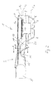
- Fig. 1 and 2 show an embodiment of a drain fitting 1 with odor trap according to the present invention.
- the drain fitting 1 is provided with a housing 2 for connection to a pipe system (not shown) having a housing 3, which forms a extending from a drain 4 to a spout 5 housing chamber 6 with a housing base 7 and housing side walls 8.
- a pipe system (not shown) having a housing 3, which forms a extending from a drain 4 to a spout 5 housing chamber 6 with a housing base 7 and housing side walls 8.
- an immersion tube 9 extending into the housing chamber 6 is provided with a central axis 9a which extends vertically, which immersion tube 9 is spaced from the housing base 7 and the housing side walls 8 and limits a reservoir volume V R which extends outside of the immersion tube 9.
- the nozzle 2 has a nozzle connection section 2a, which connects the interior of the nozzle 2 with the rest of the housing chamber 6 and forms part of the reservoir volume V R , wherein the odor trap is effected by means of barrier water stored in the dip tube 9 and in the reservoir volume V R.
- the sealing water can occupy a maximum water level X 1 (before an accident) and a minimum level below it X 2 (after an accident), as indicated by dashed lines in Fig. 2 is shown.
- the bottom 12 of the nozzle 2 has a raised from a first side wall 13 to an opposite second side wall 14 of the nozzle 2 elevation 15 with a height offset 14a, which narrows the flow channel 11 temporarily and in the nozzle connection portion 2a, the reservoir volume V R to the outlet 5 out limited.
- the elevation 15 is a structural element 10, which causes a change in the flow characteristics or the flow behavior in the leading from the interior of the dip tube 9 to the nozzle connection portion 2a flow channel 11.
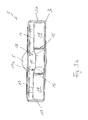
- FIG. 3 shows the elevation 15 to the two side walls 13 and 14 of the nozzle 2 towards and is in the middle between the side walls 13 and 14 lowest.
- the in Fig. 3 section shown is along the in Fig. 2 shown section line AA out.
- the portion 18 of the elevation 15, which has a relatively small height, is separated from the two portions 17 with a greater height by bulkheads 16, which together with the each adjacent side wall 13 and 14 and the respective section 17 form stowage pockets 19, in which in case of failure, if in the pipe system there is a negative pressure, a higher water level sets, as in the area between the bulkheads 16.
- This causes a disruption of the Flow in the portion of the flow channel 11 between the elevation 15 and the lower edge of the dip tube 9, whereby air is sucked through the dip tube 9 in the conduit system, which leads to a pressure equalization.
- the sealing water comes to rest again and settles at the sealing water level X 2 , which is slightly below the maximum sealing water level X 1 .
- both bulkheads 16 are connected both to the bottom in the nozzle connection section 2 a and to the front part of the elevation 15.
- the height of the bulkhead walls 16 corresponds to the height of the elevation 15 at the highest point, that is to say the maximum height of the elevation 15.
- the survey 15 has a special shape.
- the surface of the elevation 15 initially rises gradually in the flow direction and then gradually decreases again after the highest point.
- the elevation 15 in the present case has a convex, namely a parabolic, course.
- the flow channel 11 is formed between the dip tube 9, in particular the lower edge of the dip tube 9, and the front end of the nozzle connection portion 2a in a special way.
- the vertical distance between the lower edge of the dip tube 9 and the housing base 7 by more as 25% smaller than the horizontal distance between the lower edge of the dip tube 9 and the closest housing side wall 8, which here, as well as the opposite side wall 8 of the housing has an oblique course.
- the housing side walls 8, as the section in the FIGS. 1 and 2 shows, at least in the lower portion of the housing chamber 6 at an angle of about 25 ° relative to the vertical center axis 9a of the dip tube. 9
- Fig. 2 shows Fig. 2 in that the bottom 12 of the neck 2 rises in the direction of flow from the beginning of the neck connection section 2a to the elevation 15 and drops again after the elevation 15.
- Fig. 4 Finally, schematically shows an example of optimally matched volume ratios.
- the volume V 1 within the dip tube 9 (which is bounded above the level X 1 and down from the level X 3 ) and the partial volume V 2 of the reservoir volume V R (which is also upwards from the level X 1 and is limited downwards from the level X 3 ) are selected so that after a reduction of the total volume V by the partial volume V 2, the sealing water level only drops by a few millimeters to the minimum sealing water level X 2 .
- the total volume V is defined as the sum of the volumes V 1 (volume dip tube), V 2 (partial volume) and V 3 (volume below X 3 ).
- the reservoir volume V R is defined as the sum of the volumes V 2 (partial volume) and V 3 (volume below X 3 ). Since the partial volume V 2 includes not only the annulus immediately around the dip tube 9, but also a part of the nozzle connection portion 2a, there is a volume ratio in which the partial volume V 2 by about the Factor 7 is greater than the volume V 1 within the dip tube 9. This ensures that a maximum sealing water level X 1, for example 50 mm, can at most fall to the minimum sealing water level of 30 mm if a malfunction due to underpressure in the pipe system occurs.
Landscapes
- Health & Medical Sciences (AREA)
- Life Sciences & Earth Sciences (AREA)
- Engineering & Computer Science (AREA)
- Hydrology & Water Resources (AREA)
- Public Health (AREA)
- Water Supply & Treatment (AREA)
- Sink And Installation For Waste Water (AREA)
- Sanitary Device For Flush Toilet (AREA)
- Self-Closing Valves And Venting Or Aerating Valves (AREA)
Priority Applications (1)
| Application Number | Priority Date | Filing Date | Title |
|---|---|---|---|
| PL09168394T PL2157249T3 (pl) | 2008-08-22 | 2009-08-21 | Armatura odpływowa z zamknięciem wodnym |
Applications Claiming Priority (1)
| Application Number | Priority Date | Filing Date | Title |
|---|---|---|---|
| DE202008011197U DE202008011197U1 (de) | 2008-08-22 | 2008-08-22 | Ablaufarmatur mit Geruchverschluss |
Publications (3)
| Publication Number | Publication Date |
|---|---|
| EP2157249A2 true EP2157249A2 (fr) | 2010-02-24 |
| EP2157249A3 EP2157249A3 (fr) | 2011-05-11 |
| EP2157249B1 EP2157249B1 (fr) | 2014-06-18 |
Family
ID=41268210
Family Applications (2)
| Application Number | Title | Priority Date | Filing Date |
|---|---|---|---|
| EP09165624.9A Active EP2157248B1 (fr) | 2008-08-22 | 2009-07-16 | Armature d'écoulement dotée d'un verrouillage des odeurs |
| EP09168394.6A Active EP2157249B1 (fr) | 2008-08-22 | 2009-08-21 | Armature d'écoulement dotée d'un siphon |
Family Applications Before (1)
| Application Number | Title | Priority Date | Filing Date |
|---|---|---|---|
| EP09165624.9A Active EP2157248B1 (fr) | 2008-08-22 | 2009-07-16 | Armature d'écoulement dotée d'un verrouillage des odeurs |
Country Status (6)
| Country | Link |
|---|---|
| EP (2) | EP2157248B1 (fr) |
| DE (1) | DE202008011197U1 (fr) |
| DK (2) | DK2157248T3 (fr) |
| ES (2) | ES2527777T3 (fr) |
| PL (2) | PL2157248T3 (fr) |
| PT (2) | PT2157248E (fr) |
Families Citing this family (6)
| Publication number | Priority date | Publication date | Assignee | Title |
|---|---|---|---|---|
| CH703597B1 (de) * | 2010-09-01 | 2012-04-30 | Urs Gassmann | Mehrzweck-Siphon. |
| DE102010044940B4 (de) * | 2010-09-10 | 2022-01-27 | Stephan Wedi | Abwasserablauf mit Geruchsverschluss |
| DE102010046179A1 (de) * | 2010-09-23 | 2012-03-29 | Stephan Wedi | Abwasserablauf mit Geruchsverschluss, insbesondere als Ablauf für Duschwannen |
| CN103104025B (zh) * | 2013-02-06 | 2015-12-09 | 开平市新明光五金制品有限公司 | 一种带垃圾桶的地漏 |
| KR20220142056A (ko) * | 2021-04-14 | 2022-10-21 | 양정석 | 층간 병원체 전파 차단 구조형 배수트랩 |
| CN113216364B (zh) * | 2021-05-25 | 2022-09-20 | 广东电白建设集团有限公司 | 一种基于虹吸效应的市政深井排水装置 |
Citations (7)
| Publication number | Priority date | Publication date | Assignee | Title |
|---|---|---|---|---|
| DE1864695U (de) | 1961-12-28 | 1962-12-27 | Gerard Beerts | Siphon fuer den ablauf von waschbecken, ausguessen, badewannen od. dgl. |
| US3651826A (en) | 1969-11-19 | 1972-03-28 | Noriatsu Kojima | Drain trap for horizontal drain pipe |
| EP0634530A1 (fr) | 1993-07-13 | 1995-01-18 | Firma Franz Viegener II | Siphon pour dispositif d'écoulement |
| EP1098041A1 (fr) | 1999-11-03 | 2001-05-09 | Force 5 S.A. | Receveur de douche du type comprenant un bac vidangeable par son fond |
| DE202005017965U1 (de) | 2005-11-15 | 2007-03-29 | Viega Gmbh & Co. Kg | Ablaufvorrichtung für eine bodengleiche Dusche |
| DE102006058259A1 (de) | 2006-12-08 | 2008-06-19 | Kludi Gmbh & Co. Kg | Flachsiphon für einen Waschtisch oder ein Spülbecken |
| DE202008001013U1 (de) | 2008-01-23 | 2009-06-18 | Viega Gmbh & Co. Kg | Ablaufarmatur, insbesondere für Dusch- oder Badewannen |
Family Cites Families (5)
| Publication number | Priority date | Publication date | Assignee | Title |
|---|---|---|---|---|
| DE9102860U1 (de) * | 1991-03-09 | 1991-05-29 | Fa. Franz Viegener Ii, 5952 Attendorn | Ablaufarmatur, vorzugsweise für Duschwannen |
| DE19649239A1 (de) * | 1996-06-27 | 1998-01-02 | Scheffer Ohg Franz | Ablaufarmatur mit einstellbarem Tauchrohr und geschweißtem Gehäuse |
| EP1798352B1 (fr) * | 2005-12-13 | 2009-05-27 | Geberit Technik Ag | Bouche d'écoulement pour des appareils sanitaires |
| DE102006053756A1 (de) * | 2006-11-13 | 2008-05-15 | Hansgrohe Ag | Ablaufarmatur |
| DE102006053751A1 (de) * | 2006-11-13 | 2008-05-15 | Hansgrohe Ag | Ablaufarmatur |
-
2008
- 2008-08-22 DE DE202008011197U patent/DE202008011197U1/de not_active Expired - Lifetime
-
2009
- 2009-07-16 PT PT91656249T patent/PT2157248E/pt unknown
- 2009-07-16 ES ES09165624.9T patent/ES2527777T3/es active Active
- 2009-07-16 DK DK09165624.9T patent/DK2157248T3/en active
- 2009-07-16 PL PL09165624T patent/PL2157248T3/pl unknown
- 2009-07-16 EP EP09165624.9A patent/EP2157248B1/fr active Active
- 2009-08-21 PT PT91683946T patent/PT2157249E/pt unknown
- 2009-08-21 DK DK09168394.6T patent/DK2157249T3/da active
- 2009-08-21 PL PL09168394T patent/PL2157249T3/pl unknown
- 2009-08-21 EP EP09168394.6A patent/EP2157249B1/fr active Active
- 2009-08-21 ES ES09168394.6T patent/ES2496667T3/es active Active
Patent Citations (7)
| Publication number | Priority date | Publication date | Assignee | Title |
|---|---|---|---|---|
| DE1864695U (de) | 1961-12-28 | 1962-12-27 | Gerard Beerts | Siphon fuer den ablauf von waschbecken, ausguessen, badewannen od. dgl. |
| US3651826A (en) | 1969-11-19 | 1972-03-28 | Noriatsu Kojima | Drain trap for horizontal drain pipe |
| EP0634530A1 (fr) | 1993-07-13 | 1995-01-18 | Firma Franz Viegener II | Siphon pour dispositif d'écoulement |
| EP1098041A1 (fr) | 1999-11-03 | 2001-05-09 | Force 5 S.A. | Receveur de douche du type comprenant un bac vidangeable par son fond |
| DE202005017965U1 (de) | 2005-11-15 | 2007-03-29 | Viega Gmbh & Co. Kg | Ablaufvorrichtung für eine bodengleiche Dusche |
| DE102006058259A1 (de) | 2006-12-08 | 2008-06-19 | Kludi Gmbh & Co. Kg | Flachsiphon für einen Waschtisch oder ein Spülbecken |
| DE202008001013U1 (de) | 2008-01-23 | 2009-06-18 | Viega Gmbh & Co. Kg | Ablaufarmatur, insbesondere für Dusch- oder Badewannen |
Also Published As
| Publication number | Publication date |
|---|---|
| PL2157248T3 (pl) | 2015-04-30 |
| ES2496667T3 (es) | 2014-09-19 |
| EP2157248B1 (fr) | 2014-11-19 |
| DE202008011197U1 (de) | 2009-12-31 |
| DK2157248T3 (en) | 2015-01-26 |
| EP2157249A3 (fr) | 2011-05-11 |
| EP2157248A3 (fr) | 2011-05-11 |
| PT2157249E (pt) | 2014-09-08 |
| PL2157249T3 (pl) | 2014-11-28 |
| PT2157248E (pt) | 2015-02-04 |
| ES2527777T3 (es) | 2015-01-29 |
| DK2157249T3 (da) | 2014-09-15 |
| EP2157249B1 (fr) | 2014-06-18 |
| EP2157248A2 (fr) | 2010-02-24 |
Similar Documents
| Publication | Publication Date | Title |
|---|---|---|
| EP2157249B1 (fr) | Armature d'écoulement dotée d'un siphon | |
| EP3791027B1 (fr) | Unité de rigole de corps de remplissage, système de rigole de corps de remplissage et éléments de regard | |
| EP3469158B1 (fr) | Soupape de vidange | |
| WO2015185460A1 (fr) | Coude de déviation | |
| EP3183048B1 (fr) | Filtre d'eau de pluie | |
| EP2508686B1 (fr) | Installation de retenue pour l'eau de précipitation et les eaux usées | |
| DE202014007392U1 (de) | Wasserablauf mit Mehrfachsiphon-Geruchsverschluss | |
| EP2157247B1 (fr) | Bouche d'écoulement | |
| EP2525002A1 (fr) | Pièce d'embranchement de conduite pour tuyaux de descente | |
| EP2369088A1 (fr) | Dispositif destiné au drainage des eaux pluviales de toit | |
| EP1882786B1 (fr) | Coude de tube pour une canalisation sanitaire | |
| DE102005012439B4 (de) | Wasserabführvorrichtung | |
| DE202018101215U1 (de) | Ablaufarmatur für eine Dusch- oder Badewanne | |
| EP3199715B1 (fr) | Trop-plein pour un bac, en particulier évier | |
| EP3272955A1 (fr) | Systeme de siphon | |
| EP4069910B1 (fr) | Dispositif de drainage | |
| EP3825479A1 (fr) | Répartiteur d'eau de chasse | |
| DE102023123249A1 (de) | Anordnungssystem zur Anordnung eines Spülbehälters eines Sanitärausstattungsgegenstandes | |
| EP2995731B1 (fr) | Dispositif d'écoulement d'eau doté d'un système de blocage d'odeur à siphons multiples | |
| EP0518912B1 (fr) | Bassin d'epuration ou de sedimentation | |
| DE102007056294B3 (de) | Tauchwandsystem zur Schwimmstoffrückhaltung in Überlaufsystemen | |
| CH716375B1 (de) | Armaturenanordnung, insbesondere zur Unterputzmontage. | |
| DE2822299A1 (de) | Regler fuer ein stroemungsmedium | |
| EP3421676B1 (fr) | Élément de siphon à installer dans un écoulement, en particulier dans un écoulement d'un urinoir sans eau | |
| EP3382193A1 (fr) | Filtre à carburant permettant de filtrer le carburant dans un véhicule automobile et véhicule automobile pourvu d'un tel filtre à carburant |
Legal Events
| Date | Code | Title | Description |
|---|---|---|---|
| PUAI | Public reference made under article 153(3) epc to a published international application that has entered the european phase |
Free format text: ORIGINAL CODE: 0009012 |
|
| AK | Designated contracting states |
Kind code of ref document: A2 Designated state(s): AT BE BG CH CY CZ DE DK EE ES FI FR GB GR HR HU IE IS IT LI LT LU LV MC MK MT NL NO PL PT RO SE SI SK SM TR |
|
| AX | Request for extension of the european patent |
Extension state: AL BA RS |
|
| REG | Reference to a national code |
Ref country code: DE Ref legal event code: R079 Ref document number: 502009009524 Country of ref document: DE Free format text: PREVIOUS MAIN CLASS: E03C0001290000 Ipc: E03F0005040000 |
|
| PUAL | Search report despatched |
Free format text: ORIGINAL CODE: 0009013 |
|
| AK | Designated contracting states |
Kind code of ref document: A3 Designated state(s): AT BE BG CH CY CZ DE DK EE ES FI FR GB GR HR HU IE IS IT LI LT LU LV MC MK MT NL NO PL PT RO SE SI SK SM TR |
|
| AX | Request for extension of the european patent |
Extension state: AL BA RS |
|
| RIC1 | Information provided on ipc code assigned before grant |
Ipc: E03F 5/04 20060101AFI20110401BHEP |
|
| 17P | Request for examination filed |
Effective date: 20110620 |
|
| 17Q | First examination report despatched |
Effective date: 20130417 |
|
| GRAP | Despatch of communication of intention to grant a patent |
Free format text: ORIGINAL CODE: EPIDOSNIGR1 |
|
| INTG | Intention to grant announced |
Effective date: 20140311 |
|
| GRAS | Grant fee paid |
Free format text: ORIGINAL CODE: EPIDOSNIGR3 |
|
| GRAA | (expected) grant |
Free format text: ORIGINAL CODE: 0009210 |
|
| AK | Designated contracting states |
Kind code of ref document: B1 Designated state(s): AT BE BG CH CY CZ DE DK EE ES FI FR GB GR HR HU IE IS IT LI LT LU LV MC MK MT NL NO PL PT RO SE SI SK SM TR |
|
| REG | Reference to a national code |
Ref country code: GB Ref legal event code: FG4D Free format text: NOT ENGLISH |
|
| REG | Reference to a national code |
Ref country code: CH Ref legal event code: NV Representative=s name: TROESCH SCHEIDEGGER WERNER AG, CH Ref country code: CH Ref legal event code: EP |
|
| REG | Reference to a national code |
Ref country code: AT Ref legal event code: REF Ref document number: 673458 Country of ref document: AT Kind code of ref document: T Effective date: 20140715 |
|
| REG | Reference to a national code |
Ref country code: IE Ref legal event code: FG4D Free format text: LANGUAGE OF EP DOCUMENT: GERMAN |
|
| REG | Reference to a national code |
Ref country code: DE Ref legal event code: R096 Ref document number: 502009009524 Country of ref document: DE Effective date: 20140731 |
|
| REG | Reference to a national code |
Ref country code: NL Ref legal event code: T3 |
|
| REG | Reference to a national code |
Ref country code: PT Ref legal event code: SC4A Free format text: AVAILABILITY OF NATIONAL TRANSLATION Effective date: 20140827 |
|
| REG | Reference to a national code |
Ref country code: DK Ref legal event code: T3 Effective date: 20140909 |
|
| REG | Reference to a national code |
Ref country code: ES Ref legal event code: FG2A Ref document number: 2496667 Country of ref document: ES Kind code of ref document: T3 Effective date: 20140919 |
|
| PG25 | Lapsed in a contracting state [announced via postgrant information from national office to epo] |
Ref country code: FI Free format text: LAPSE BECAUSE OF FAILURE TO SUBMIT A TRANSLATION OF THE DESCRIPTION OR TO PAY THE FEE WITHIN THE PRESCRIBED TIME-LIMIT Effective date: 20140618 Ref country code: LT Free format text: LAPSE BECAUSE OF FAILURE TO SUBMIT A TRANSLATION OF THE DESCRIPTION OR TO PAY THE FEE WITHIN THE PRESCRIBED TIME-LIMIT Effective date: 20140618 Ref country code: GR Free format text: LAPSE BECAUSE OF FAILURE TO SUBMIT A TRANSLATION OF THE DESCRIPTION OR TO PAY THE FEE WITHIN THE PRESCRIBED TIME-LIMIT Effective date: 20140919 Ref country code: CY Free format text: LAPSE BECAUSE OF FAILURE TO SUBMIT A TRANSLATION OF THE DESCRIPTION OR TO PAY THE FEE WITHIN THE PRESCRIBED TIME-LIMIT Effective date: 20140618 Ref country code: NO Free format text: LAPSE BECAUSE OF FAILURE TO SUBMIT A TRANSLATION OF THE DESCRIPTION OR TO PAY THE FEE WITHIN THE PRESCRIBED TIME-LIMIT Effective date: 20140918 |
|
| REG | Reference to a national code |
Ref country code: LT Ref legal event code: MG4D |
|
| PG25 | Lapsed in a contracting state [announced via postgrant information from national office to epo] |
Ref country code: SE Free format text: LAPSE BECAUSE OF FAILURE TO SUBMIT A TRANSLATION OF THE DESCRIPTION OR TO PAY THE FEE WITHIN THE PRESCRIBED TIME-LIMIT Effective date: 20140618 Ref country code: HR Free format text: LAPSE BECAUSE OF FAILURE TO SUBMIT A TRANSLATION OF THE DESCRIPTION OR TO PAY THE FEE WITHIN THE PRESCRIBED TIME-LIMIT Effective date: 20140618 Ref country code: LV Free format text: LAPSE BECAUSE OF FAILURE TO SUBMIT A TRANSLATION OF THE DESCRIPTION OR TO PAY THE FEE WITHIN THE PRESCRIBED TIME-LIMIT Effective date: 20140618 |
|
| REG | Reference to a national code |
Ref country code: PL Ref legal event code: T3 |
|
| PG25 | Lapsed in a contracting state [announced via postgrant information from national office to epo] |
Ref country code: RO Free format text: LAPSE BECAUSE OF FAILURE TO SUBMIT A TRANSLATION OF THE DESCRIPTION OR TO PAY THE FEE WITHIN THE PRESCRIBED TIME-LIMIT Effective date: 20140618 Ref country code: EE Free format text: LAPSE BECAUSE OF FAILURE TO SUBMIT A TRANSLATION OF THE DESCRIPTION OR TO PAY THE FEE WITHIN THE PRESCRIBED TIME-LIMIT Effective date: 20140618 |
|
| REG | Reference to a national code |
Ref country code: SK Ref legal event code: T3 Ref document number: E 17340 Country of ref document: SK |
|
| PG25 | Lapsed in a contracting state [announced via postgrant information from national office to epo] |
Ref country code: IS Free format text: LAPSE BECAUSE OF FAILURE TO SUBMIT A TRANSLATION OF THE DESCRIPTION OR TO PAY THE FEE WITHIN THE PRESCRIBED TIME-LIMIT Effective date: 20141018 |
|
| REG | Reference to a national code |
Ref country code: DE Ref legal event code: R097 Ref document number: 502009009524 Country of ref document: DE |
|
| PG25 | Lapsed in a contracting state [announced via postgrant information from national office to epo] |
Ref country code: LU Free format text: LAPSE BECAUSE OF FAILURE TO SUBMIT A TRANSLATION OF THE DESCRIPTION OR TO PAY THE FEE WITHIN THE PRESCRIBED TIME-LIMIT Effective date: 20140821 Ref country code: MC Free format text: LAPSE BECAUSE OF FAILURE TO SUBMIT A TRANSLATION OF THE DESCRIPTION OR TO PAY THE FEE WITHIN THE PRESCRIBED TIME-LIMIT Effective date: 20140618 |
|
| PLBE | No opposition filed within time limit |
Free format text: ORIGINAL CODE: 0009261 |
|
| STAA | Information on the status of an ep patent application or granted ep patent |
Free format text: STATUS: NO OPPOSITION FILED WITHIN TIME LIMIT |
|
| REG | Reference to a national code |
Ref country code: IE Ref legal event code: MM4A |
|
| 26N | No opposition filed |
Effective date: 20150319 |
|
| PG25 | Lapsed in a contracting state [announced via postgrant information from national office to epo] |
Ref country code: SI Free format text: LAPSE BECAUSE OF FAILURE TO SUBMIT A TRANSLATION OF THE DESCRIPTION OR TO PAY THE FEE WITHIN THE PRESCRIBED TIME-LIMIT Effective date: 20140618 |
|
| PG25 | Lapsed in a contracting state [announced via postgrant information from national office to epo] |
Ref country code: IE Free format text: LAPSE BECAUSE OF NON-PAYMENT OF DUE FEES Effective date: 20140821 |
|
| PG25 | Lapsed in a contracting state [announced via postgrant information from national office to epo] |
Ref country code: SM Free format text: LAPSE BECAUSE OF FAILURE TO SUBMIT A TRANSLATION OF THE DESCRIPTION OR TO PAY THE FEE WITHIN THE PRESCRIBED TIME-LIMIT Effective date: 20140618 |
|
| PG25 | Lapsed in a contracting state [announced via postgrant information from national office to epo] |
Ref country code: MT Free format text: LAPSE BECAUSE OF FAILURE TO SUBMIT A TRANSLATION OF THE DESCRIPTION OR TO PAY THE FEE WITHIN THE PRESCRIBED TIME-LIMIT Effective date: 20140618 Ref country code: BG Free format text: LAPSE BECAUSE OF FAILURE TO SUBMIT A TRANSLATION OF THE DESCRIPTION OR TO PAY THE FEE WITHIN THE PRESCRIBED TIME-LIMIT Effective date: 20140618 |
|
| PG25 | Lapsed in a contracting state [announced via postgrant information from national office to epo] |
Ref country code: HU Free format text: LAPSE BECAUSE OF FAILURE TO SUBMIT A TRANSLATION OF THE DESCRIPTION OR TO PAY THE FEE WITHIN THE PRESCRIBED TIME-LIMIT; INVALID AB INITIO Effective date: 20090821 Ref country code: TR Free format text: LAPSE BECAUSE OF FAILURE TO SUBMIT A TRANSLATION OF THE DESCRIPTION OR TO PAY THE FEE WITHIN THE PRESCRIBED TIME-LIMIT Effective date: 20140618 |
|
| REG | Reference to a national code |
Ref country code: FR Ref legal event code: PLFP Year of fee payment: 8 |
|
| REG | Reference to a national code |
Ref country code: DE Ref legal event code: R082 Ref document number: 502009009524 Country of ref document: DE Representative=s name: COHAUSZ & FLORACK PATENT- UND RECHTSANWAELTE P, DE Ref country code: DE Ref legal event code: R081 Ref document number: 502009009524 Country of ref document: DE Owner name: VIEGA TECHNOLOGY GMBH & CO. KG, DE Free format text: FORMER OWNER: VIEGA GMBH & CO. KG, 57439 ATTENDORN, DE |
|
| REG | Reference to a national code |
Ref country code: NL Ref legal event code: PD Owner name: VIEGA TECHNOLOGY GMBH & CO. KG; DE Free format text: DETAILS ASSIGNMENT: CHANGE OF OWNER(S), ASSIGNMENT; FORMER OWNER NAME: VIEGA GMBH & CO. KG Effective date: 20170412 |
|
| REG | Reference to a national code |
Ref country code: SK Ref legal event code: PC4A Ref document number: E 17340 Country of ref document: SK Owner name: VIEGA TECHNOLOGY GMBH & CO. KG, ATTENDORN, DE Free format text: FORMER OWNER: VIEGA GMBH & CO. KG, ATTENDORN, DE Effective date: 20161230 Ref country code: GB Ref legal event code: 732E Free format text: REGISTERED BETWEEN 20170706 AND 20170715 |
|
| REG | Reference to a national code |
Ref country code: FR Ref legal event code: PLFP Year of fee payment: 9 |
|
| REG | Reference to a national code |
Ref country code: ES Ref legal event code: PC2A Owner name: VIEGA TECHNOLOGY GMBH & CO. KG Effective date: 20170925 |
|
| REG | Reference to a national code |
Ref country code: FR Ref legal event code: TP Owner name: VIEGA TECHNOLOGY GMBH & CO. KG, DE Effective date: 20171013 |
|
| REG | Reference to a national code |
Ref country code: CH Ref legal event code: PUE Owner name: VIEGA TECHNOLOGY GMBH AND CO. KG, DE Free format text: FORMER OWNER: VIEGA GMBH AND CO. KG, DE |
|
| PG25 | Lapsed in a contracting state [announced via postgrant information from national office to epo] |
Ref country code: MK Free format text: LAPSE BECAUSE OF FAILURE TO SUBMIT A TRANSLATION OF THE DESCRIPTION OR TO PAY THE FEE WITHIN THE PRESCRIBED TIME-LIMIT Effective date: 20140618 |
|
| REG | Reference to a national code |
Ref country code: FR Ref legal event code: PLFP Year of fee payment: 10 |
|
| PGFP | Annual fee paid to national office [announced via postgrant information from national office to epo] |
Ref country code: NL Payment date: 20210824 Year of fee payment: 13 |
|
| PGFP | Annual fee paid to national office [announced via postgrant information from national office to epo] |
Ref country code: CZ Payment date: 20210715 Year of fee payment: 13 Ref country code: AT Payment date: 20210824 Year of fee payment: 13 |
|
| PGFP | Annual fee paid to national office [announced via postgrant information from national office to epo] |
Ref country code: BE Payment date: 20210823 Year of fee payment: 13 Ref country code: PL Payment date: 20210714 Year of fee payment: 13 Ref country code: SK Payment date: 20210714 Year of fee payment: 13 Ref country code: DK Payment date: 20210826 Year of fee payment: 13 |
|
| PGFP | Annual fee paid to national office [announced via postgrant information from national office to epo] |
Ref country code: PT Payment date: 20210720 Year of fee payment: 13 |
|
| PGFP | Annual fee paid to national office [announced via postgrant information from national office to epo] |
Ref country code: GB Payment date: 20220822 Year of fee payment: 14 Ref country code: ES Payment date: 20220922 Year of fee payment: 14 |
|
| PGFP | Annual fee paid to national office [announced via postgrant information from national office to epo] |
Ref country code: FR Payment date: 20220822 Year of fee payment: 14 |
|
| REG | Reference to a national code |
Ref country code: DK Ref legal event code: EBP Effective date: 20220831 |
|
| REG | Reference to a national code |
Ref country code: NL Ref legal event code: MM Effective date: 20220901 |
|
| REG | Reference to a national code |
Ref country code: SK Ref legal event code: MM4A Ref document number: E 17340 Country of ref document: SK Effective date: 20220821 |
|
| REG | Reference to a national code |
Ref country code: AT Ref legal event code: MM01 Ref document number: 673458 Country of ref document: AT Kind code of ref document: T Effective date: 20220821 |
|
| PG25 | Lapsed in a contracting state [announced via postgrant information from national office to epo] |
Ref country code: PT Free format text: LAPSE BECAUSE OF NON-PAYMENT OF DUE FEES Effective date: 20230221 Ref country code: CZ Free format text: LAPSE BECAUSE OF NON-PAYMENT OF DUE FEES Effective date: 20220821 Ref country code: AT Free format text: LAPSE BECAUSE OF NON-PAYMENT OF DUE FEES Effective date: 20220821 |
|
| REG | Reference to a national code |
Ref country code: BE Ref legal event code: MM Effective date: 20220831 |
|
| PG25 | Lapsed in a contracting state [announced via postgrant information from national office to epo] |
Ref country code: SK Free format text: LAPSE BECAUSE OF NON-PAYMENT OF DUE FEES Effective date: 20220821 |
|
| PG25 | Lapsed in a contracting state [announced via postgrant information from national office to epo] |
Ref country code: NL Free format text: LAPSE BECAUSE OF NON-PAYMENT OF DUE FEES Effective date: 20220901 |
|
| PG25 | Lapsed in a contracting state [announced via postgrant information from national office to epo] |
Ref country code: DK Free format text: LAPSE BECAUSE OF NON-PAYMENT OF DUE FEES Effective date: 20220831 |
|
| PG25 | Lapsed in a contracting state [announced via postgrant information from national office to epo] |
Ref country code: BE Free format text: LAPSE BECAUSE OF NON-PAYMENT OF DUE FEES Effective date: 20220831 |
|
| PG25 | Lapsed in a contracting state [announced via postgrant information from national office to epo] |
Ref country code: PL Free format text: LAPSE BECAUSE OF NON-PAYMENT OF DUE FEES Effective date: 20220821 |
|
| GBPC | Gb: european patent ceased through non-payment of renewal fee |
Effective date: 20230821 |
|
| PG25 | Lapsed in a contracting state [announced via postgrant information from national office to epo] |
Ref country code: GB Free format text: LAPSE BECAUSE OF NON-PAYMENT OF DUE FEES Effective date: 20230821 |
|
| PG25 | Lapsed in a contracting state [announced via postgrant information from national office to epo] |
Ref country code: GB Free format text: LAPSE BECAUSE OF NON-PAYMENT OF DUE FEES Effective date: 20230821 Ref country code: FR Free format text: LAPSE BECAUSE OF NON-PAYMENT OF DUE FEES Effective date: 20230831 |
|
| REG | Reference to a national code |
Ref country code: ES Ref legal event code: FD2A Effective date: 20241001 |
|
| PG25 | Lapsed in a contracting state [announced via postgrant information from national office to epo] |
Ref country code: ES Free format text: LAPSE BECAUSE OF NON-PAYMENT OF DUE FEES Effective date: 20230822 |
|
| PGFP | Annual fee paid to national office [announced via postgrant information from national office to epo] |
Ref country code: CH Payment date: 20240901 Year of fee payment: 16 |
|
| PG25 | Lapsed in a contracting state [announced via postgrant information from national office to epo] |
Ref country code: ES Free format text: LAPSE BECAUSE OF NON-PAYMENT OF DUE FEES Effective date: 20230822 |
|
| PGFP | Annual fee paid to national office [announced via postgrant information from national office to epo] |
Ref country code: IT Payment date: 20240827 Year of fee payment: 16 |
|
| PGFP | Annual fee paid to national office [announced via postgrant information from national office to epo] |
Ref country code: DE Payment date: 20250826 Year of fee payment: 17 |
|
| REG | Reference to a national code |
Ref country code: CH Ref legal event code: H13 Free format text: ST27 STATUS EVENT CODE: U-0-0-H10-H13 (AS PROVIDED BY THE NATIONAL OFFICE) Effective date: 20260324 |
|
| PG25 | Lapsed in a contracting state [announced via postgrant information from national office to epo] |
Ref country code: CH Free format text: LAPSE BECAUSE OF NON-PAYMENT OF DUE FEES Effective date: 20250831 |