EP3382193A1 - Filtre à carburant permettant de filtrer le carburant dans un véhicule automobile et véhicule automobile pourvu d'un tel filtre à carburant - Google Patents
Filtre à carburant permettant de filtrer le carburant dans un véhicule automobile et véhicule automobile pourvu d'un tel filtre à carburant Download PDFInfo
- Publication number
- EP3382193A1 EP3382193A1 EP18163598.8A EP18163598A EP3382193A1 EP 3382193 A1 EP3382193 A1 EP 3382193A1 EP 18163598 A EP18163598 A EP 18163598A EP 3382193 A1 EP3382193 A1 EP 3382193A1
- Authority
- EP
- European Patent Office
- Prior art keywords
- fuel
- outlet
- fuel filter
- sump
- overflow
- Prior art date
- Legal status (The legal status is an assumption and is not a legal conclusion. Google has not performed a legal analysis and makes no representation as to the accuracy of the status listed.)
- Granted
Links
Images

Classifications
-
- F—MECHANICAL ENGINEERING; LIGHTING; HEATING; WEAPONS; BLASTING
- F02—COMBUSTION ENGINES; HOT-GAS OR COMBUSTION-PRODUCT ENGINE PLANTS
- F02M—SUPPLYING COMBUSTION ENGINES IN GENERAL WITH COMBUSTIBLE MIXTURES OR CONSTITUENTS THEREOF
- F02M37/00—Apparatus or systems for feeding liquid fuel from storage containers to carburettors or fuel-injection apparatus; Arrangements for purifying liquid fuel specially adapted for, or arranged on, internal-combustion engines
- F02M37/22—Arrangements for purifying liquid fuel specially adapted for, or arranged on, internal-combustion engines, e.g. arrangements in the feeding system
- F02M37/24—Arrangements for purifying liquid fuel specially adapted for, or arranged on, internal-combustion engines, e.g. arrangements in the feeding system characterised by water separating means
-
- F—MECHANICAL ENGINEERING; LIGHTING; HEATING; WEAPONS; BLASTING
- F02—COMBUSTION ENGINES; HOT-GAS OR COMBUSTION-PRODUCT ENGINE PLANTS
- F02M—SUPPLYING COMBUSTION ENGINES IN GENERAL WITH COMBUSTIBLE MIXTURES OR CONSTITUENTS THEREOF
- F02M37/00—Apparatus or systems for feeding liquid fuel from storage containers to carburettors or fuel-injection apparatus; Arrangements for purifying liquid fuel specially adapted for, or arranged on, internal-combustion engines
- F02M37/22—Arrangements for purifying liquid fuel specially adapted for, or arranged on, internal-combustion engines, e.g. arrangements in the feeding system
- F02M37/32—Arrangements for purifying liquid fuel specially adapted for, or arranged on, internal-combustion engines, e.g. arrangements in the feeding system characterised by filters or filter arrangements
-
- F—MECHANICAL ENGINEERING; LIGHTING; HEATING; WEAPONS; BLASTING
- F02—COMBUSTION ENGINES; HOT-GAS OR COMBUSTION-PRODUCT ENGINE PLANTS
- F02M—SUPPLYING COMBUSTION ENGINES IN GENERAL WITH COMBUSTIBLE MIXTURES OR CONSTITUENTS THEREOF
- F02M37/00—Apparatus or systems for feeding liquid fuel from storage containers to carburettors or fuel-injection apparatus; Arrangements for purifying liquid fuel specially adapted for, or arranged on, internal-combustion engines
- F02M37/22—Arrangements for purifying liquid fuel specially adapted for, or arranged on, internal-combustion engines, e.g. arrangements in the feeding system
- F02M37/54—Arrangements for purifying liquid fuel specially adapted for, or arranged on, internal-combustion engines, e.g. arrangements in the feeding system characterised by air purging means
Definitions
- the invention relates to a fuel filter for filtering fuel in a motor vehicle, comprising a housing, wherein the housing encloses a pressure region, in which a filter chamber is arranged, according to the preamble of claim 1. Furthermore, the invention relates to a motor vehicle with a fuel tank and an internal combustion engine , wherein in a fuel line such a fuel filter is arranged.
- Such fuel filters are used in automobiles to filter contaminants from the fuel that is directed from the fuel tank to the engine.
- the fuel is passed through a filter element, which filters out the contamination from the fuel.
- This filter element must be changed at regular intervals.
- the fuel from the pressure range runs back into the fuel tank via the return line.
- the return line to the fuel tank can run completely empty.
- the fuel filter must be refilled with fuel. This can be done for example by a hand pump.
- pressure can then be re-established and the engine receives fuel and can start.
- the thereby displaced air flows from the pressure range of the filter chamber through a throttle in a venting channel and is subsequently returned to the fuel tank via the return passage. If there is no more air in the pressure range, the fuel flows through the throttle into the venting channel.
- the air in the vent passage is gradually discharged to the fuel tank.
- the water collecting space is arranged below the filter chamber.
- the filling quantity limitation for water in the water collection chamber is provided by a throttle in a ventilation channel.
- Filter room and water collection chamber are hydraulically connected.
- the two throttles discharge at different levels into the venting duct, those from the filter room usually at the top, and those from the water collecting chamber below. If the vehicle now stands in the parking lot after maintenance, air that has risen in the ventilation duct can enter the pressure area of the filter chamber through the upper throttle. In return, fuel passes through the lower throttle from the water collection chamber into the ventilation duct.
- the pressure range of the filter chamber and the water chamber can run down to the level of the lower restrictor. If the engine is to be started later, the air from the pressure range must be displaced by the pumped fuel into the venting channel before pressure is built up and the engine can start.
- the time to engine start is proportional to the amount of air in the pressure area of the filter room and water collection room. Long engine start times can lead to annoyance of the customer, very long start times even damage to the high pressure pump due to mixed friction or dry running.
- a fuel supply device for a motor vehicle in which a siphon is formed in a fuel line to prevent the undesirable entry of air into the fuel line.
- the present invention has for its object to provide an improved or at least other embodiment of a fuel filter or a motor vehicle, which is characterized in particular by an improved engine start after maintenance.
- the invention is based on the general idea, the vent channel and the drain line from the water collection area first to open into a sump and provided by the sump from an overflow line or return line to the fuel tank. Furthermore, both the vent channel and the drain line from the water collection area is provided with a siphon, which prevent unwanted ingress of air. According to the invention, it is therefore provided that the venting channel has an outlet which opens into the collecting space, that the outlet of the venting channel is below the overflow of the sump, and that the discharge line has an outlet which opens into the collecting space, and that in or at the Drain line from the water collection area a siphon is formed. Due to the fact that the outlet of the ventilation channel is located below the sump overflow, the outlet of the ventilation channel ends below a liquid level.
- a siphon is understood to mean a part of a fluid passage which is permanently filled by a liquid.
- a siphon may be formed, for example, by a curved conduit filled with liquid.
- a mouth of a conduit which ends below a liquid level form a siphon.
- a favorable solution provides that the outlet of the ventilation duct viewed in the direction of gravity below the sump overflow, even if the fuel filter deviates from its intended installation position by up to 6 °, preferably by up to 20 °, particularly preferably by up to 45 ° , This maintains the siphon effect at the outlet of the ventilation duct, even if the fuel filter is tilted by 6 °, 20 ° or 45 ° with respect to the intended installation position. This may occur, for example, when the motor vehicle in which the fuel filter is installed is in an inclined position.
- the siphon of the drain line from the water collection area is formed by the drain line has a siphon section, which lies below the outlet in the drain line.
- the drain line is directed downwards. Because the siphon section lies below the outlet, the drain line must therefore extend upward again from the siphon section. Therefore, the liquid remains in the siphon section, so that the entry of air through the drain line can be prevented.
- a particularly favorable possibility provides that the siphon section of the drain line is below the outlet in the drain line, even if the fuel filter deviates from its intended installation position by 6 °, preferably by up to 20 °, particularly preferably by up to 45 °.
- the siphon must be located sufficiently far below the outlet. This ensures that even if the fuel filter is tilted by its default installation position by 6 °, 20 ° or 45 ° in any direction, yet the siphon effect is maintained.
- a tilt of the motor vehicle for example, when the vehicle is parked in a sloping parking lot, be preserved.
- An advantageous solution provides that the siphon of the drain line from the water collection area is formed by an outlet in the drain line is arranged below the overflow of the sump. As a result, the outlet is below a liquid level, so that thereby the siphon effect can be achieved.
- a further advantageous solution provides that the outlet of the drain line is arranged below the overflow of the sump, even if the fuel filter from its intended installation position by up to 6 °, preferably by up to 20 ° and most preferably by up to 45 °, deviates.
- the outlet of the drain line is below the liquid level, even if the fuel filter is tilted from its installation position by 6 °, 20 ° or 45 °.
- the outlet remains below the liquid level, even if the motor vehicle has an inclined position.
- a favorable variant provides that the water collection area is arranged on the clean side in a lower region of the pressure range, preferably in a lower fourth of the pressure range.
- Water usually has a higher density than the fuel, so that the water accumulates in the lower part of the housing.
- a further favorable variant provides that the fluid connection is arranged from the pressure region to the venting channel on the raw side. As a result, the air that is to be vented through the vent channel, coming from the raw side must not pass through the filter element before it can be vented.
- the fluid connection to the venting channel is arranged in an upper region of the pressure region, preferably at an uppermost point.
- the vent channel serves to discharge air from the pressure area.
- the air accumulates at the top due to the lower density. Therefore, the breather channel, which is located in an upper portion of the pressure range, the air can be largely derived from the pressure range.
- the invention is based on the general idea of equipping in a motor vehicle with a fuel tank, an internal combustion engine and a fuel line, which directs fuel from the fuel tank to the internal combustion engine, with a fuel filter as described above the fuel line is arranged and filters the fuel.
- a fuel filter as described above the fuel line is arranged and filters the fuel.
- a further advantageous possibility provides that the motor vehicle has an overflow line which forms a fluid guide for the fuel or water from the overflow of the sump to the fuel tank.
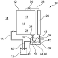
- the motor vehicle 11 has, for example, an internal combustion engine, a fuel tank 13 and a fuel line 15, with which fuel is passed from the fuel tank 13 to the internal combustion engine.
- the fuel filter 10 is disposed in the fuel line 15 to filter the fuel that is directed to the engine.
- the fuel filter 10 has a housing 12 which encloses a pressure region 14, which comprises a filter chamber 18. Furthermore, the fuel filter 10 has a filter element 16 which is arranged in a filter chamber 18 and separates a raw side 20 from a clean side 22. In addition, a water collecting area 24 is provided, which is arranged in the pressure region 14 and is fluidically connected to the filter chamber 18, in particular to the clean side 22. The water collecting area is preferably arranged at the bottom in the gravity direction, so that the water can accumulate in the water collecting area 24.
- a venting channel 26 is provided, which is fluidically connected to the pressure region 14 by a fluid connection 28.
- a first throttle 30 is arranged, so that gases, such as air, can be conducted relatively quickly from the pressure region 14, while the fuel can flow from the pressure region 14 only very slowly.
- a drain pipe 32 is provided from the water collecting area 24.
- a second throttle 34 is arranged in the drain line 32. Through the throttle 34 occur during operation of the vehicle permanently small amounts of liquid from the pressure range 14 and thus cause a maximum level for water in the water collection area 24th
- the housing 12 has a collecting space 36, which forms a sump 38. Both the venting channel 26 and the drainage line 32 open into the collecting space 36, so that the sump 38 is filled both by the discharge line 32 and by the venting channel 26.
- an overflow 40 is provided, through which fuel from the sump 38 can be derived.
- An overflow conduit 50 connects the weir 40 to the fuel tank 13 so that the fuel can flow back into the fuel tank 13 of the motor vehicle 11.
- the venting channel 26 has an outlet 42 which lies in the direction of gravity below the overflow 40 from the sump 38.
- the outlet 42 is usually located below a liquid level 52 in the sump 38.
- no air can flow back into the venting channel 26. Only fuel from the sump 38 can flow back through the vent passage 26. As a result, emptying of the pressure region 14 of the housing 12 can be prevented.
- the outlet 42 is located so far below the overflow 40, that even with an inclination of the fuel filter away from the intended installation position by up to 6 °, preferably by up to 20 °, particularly preferably by up to 45 °, the outlet 42 always is still below the liquid level 52.
- the motor vehicle 11 has an inclined position, for example was turned off at an angle, continue to prevent the ingress of air into the vent channel 26.
- the skew tolerance thus caused can be influenced by the positioning of the overflow 40 to the outlet 42. If the lateral distance between the overflow 40 and the outlet 42 is reduced, larger skew tolerances are achieved. In this way, skew tolerances up to 45 ° and above are possible.
- the drain line 32 from the water collection area 24 to a siphon 44 impedes the ingress of air through the drain line 32 into the water collection area 24.
- the siphon 44 may be formed in or on the drain line 32.
- the siphon 44 is formed by a profile of the drain line 32.
- the drain line has a siphon section 46, which is arranged below an outlet 43 of the drain line 32.
- the siphon section 46 is permanently filled with liquid, so that the liquid forms a barrier to gases, in particular air. As a result, no air can flow through the drain line 32 back into the water collection area 24.
- the siphon section 46 is formed by a substantially vertically extending, preferably tubular wall 48. As a result, the siphon section 46 forms a fluid passage which extends from the water collection region from below to above and which is filled with liquid, in particular fuel.
- Substantially vertical means that a deviation of "vertical" of up to 6 ° is allowed.
- the term vertical refers to the direction of gravity in the installation position.
- the siphon section 46 is arranged in such a way that at least one section of the siphon section 46 also lies below the outlet 43 at an inclined position of up to 6 °, preferably up to 20 ° and particularly preferably up to 45 °.
- the siphon 44 of the drain line 32 is formed by the fact that the outlet 43 of the drain line 32 is below a liquid level 52 of the sump 38.
- the outlet 43 of the discharge line 32 viewed in the direction of gravity, lies below the overflow 40 of the sump.
- the outlet 43 of the drain line 32 is arranged so far below the overflow 40, that even with a deviation, so inclination of the fuel filter, to its intended installation position by up to 6 °, preferably by up to 20 °, particularly preferably by up to 45 °
- the outlet 43 is still below the overflow 40, so that the outlet 43 is still below the liquid level 52, so that the siphon remains formed.
- the skew tolerance thus caused can be influenced by the positioning of the overflow 40 to the outlet 43. If the lateral distance between the overflow 40 and the outlet 43 is reduced, larger skew tolerances are achieved. In this way, skew tolerances up to 45 ° and above are possible.
- the outlet 43 of the drain line 32 can lie below the liquid level 52 and, in addition, a siphon section 46 can be provided which lies below the outlet 43.
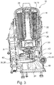
- the drain line 32 has according to Fig. 3 a siphon portion 46 formed by the wall 48.
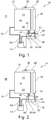
- the outlet 43 is arranged from the drain line 32 below the liquid level 52 in the sump 38, as for example in Fig. 4 you can see.
- the fuel filter 10 is tilted unfavorably from its intended installation position, so that at the outlet 43 of the drain line 32, the liquid level 52 is below the outlet 43. Nevertheless, the siphon action is due to the siphon portion 46 formed by the wall 48.
- the filter element 16 is flowed through radially from outside to inside.
- the venting channel 26 extends at least partially within a region enclosed by the filter element 16. As a result, the air accumulated in the pressure region 14 at the top can be conducted through the venting channel 26 downwards into the collecting space 36.
Landscapes
- Engineering & Computer Science (AREA)
- Chemical & Material Sciences (AREA)
- Combustion & Propulsion (AREA)
- Mechanical Engineering (AREA)
- General Engineering & Computer Science (AREA)
- Cooling, Air Intake And Gas Exhaust, And Fuel Tank Arrangements In Propulsion Units (AREA)
Applications Claiming Priority (1)
| Application Number | Priority Date | Filing Date | Title |
|---|---|---|---|
| DE102017205446.8A DE102017205446A1 (de) | 2017-03-30 | 2017-03-30 | Kraftstofffilter zum Filtern von Kraftstoff in einem Kraftfahrzeug und Kraftfahrzeug mit einem solchen Kraftstofffilter |
Publications (2)
| Publication Number | Publication Date |
|---|---|
| EP3382193A1 true EP3382193A1 (fr) | 2018-10-03 |
| EP3382193B1 EP3382193B1 (fr) | 2019-08-07 |
Family
ID=61763879
Family Applications (1)
| Application Number | Title | Priority Date | Filing Date |
|---|---|---|---|
| EP18163598.8A Active EP3382193B1 (fr) | 2017-03-30 | 2018-03-23 | Filtre à carburant permettant de filtrer le carburant dans un véhicule automobile et véhicule automobile pourvu d'un tel filtre à carburant |
Country Status (2)
| Country | Link |
|---|---|
| EP (1) | EP3382193B1 (fr) |
| DE (1) | DE102017205446A1 (fr) |
Cited By (1)
| Publication number | Priority date | Publication date | Assignee | Title |
|---|---|---|---|---|
| CN116163869A (zh) * | 2023-03-15 | 2023-05-26 | 一汽解放汽车有限公司 | 排气结构、燃油滤清器及车辆 |
Citations (4)
| Publication number | Priority date | Publication date | Assignee | Title |
|---|---|---|---|---|
| US3368681A (en) * | 1965-03-12 | 1968-02-13 | Bendix Corp | Water discharge device |
| EP1935468A1 (fr) * | 2006-12-20 | 2008-06-25 | Mahle International GmbH | Filtre à carburant |
| DE102013009750A1 (de) * | 2013-06-11 | 2014-12-11 | Daimler Ag | Kraftstoffversorgungseinrichtung für eine Verbrennungskraftmaschine eines Kraftwagens |
| DE102015003165A1 (de) * | 2015-03-13 | 2016-09-15 | Mann + Hummel Gmbh | Kraftstofffilter mit einem Kraftstofffiltereinsatz mit einem Vor- und einem Hauptfilterelement |
-
2017
- 2017-03-30 DE DE102017205446.8A patent/DE102017205446A1/de not_active Withdrawn
-
2018
- 2018-03-23 EP EP18163598.8A patent/EP3382193B1/fr active Active
Patent Citations (4)
| Publication number | Priority date | Publication date | Assignee | Title |
|---|---|---|---|---|
| US3368681A (en) * | 1965-03-12 | 1968-02-13 | Bendix Corp | Water discharge device |
| EP1935468A1 (fr) * | 2006-12-20 | 2008-06-25 | Mahle International GmbH | Filtre à carburant |
| DE102013009750A1 (de) * | 2013-06-11 | 2014-12-11 | Daimler Ag | Kraftstoffversorgungseinrichtung für eine Verbrennungskraftmaschine eines Kraftwagens |
| DE102015003165A1 (de) * | 2015-03-13 | 2016-09-15 | Mann + Hummel Gmbh | Kraftstofffilter mit einem Kraftstofffiltereinsatz mit einem Vor- und einem Hauptfilterelement |
Cited By (2)
| Publication number | Priority date | Publication date | Assignee | Title |
|---|---|---|---|---|
| CN116163869A (zh) * | 2023-03-15 | 2023-05-26 | 一汽解放汽车有限公司 | 排气结构、燃油滤清器及车辆 |
| CN116163869B (zh) * | 2023-03-15 | 2024-05-14 | 一汽解放汽车有限公司 | 排气结构、燃油滤清器及车辆 |
Also Published As
| Publication number | Publication date |
|---|---|
| EP3382193B1 (fr) | 2019-08-07 |
| DE102017205446A1 (de) | 2018-10-04 |
Similar Documents
| Publication | Publication Date | Title |
|---|---|---|
| DE102007054901B4 (de) | Ölbehälter mit Ölfilter | |
| DE102005051263B4 (de) | Öltankanordnung mit trockenem Sumpf | |
| EP2335794B1 (fr) | Dispositif de retenue de liquide | |
| DE102004032251B4 (de) | Vorrichtung zur Abscheidung von Wasser und zur Ausfilterung von Verunreinigungen | |
| DE102014013628B4 (de) | Wasserabscheider mit durch Schwimmerventil gesichertem Wasserüberlauf | |
| DE1231480B (de) | Wasserablassvorrichtung zur Entfernung von Wasser aus der vom Sumpf eines Brennstoffilter-Wasserabscheiders kommenden Fluessigkeit | |
| DE10238237A1 (de) | Kammerentleerungseinrichtung | |
| EP3382193B1 (fr) | Filtre à carburant permettant de filtrer le carburant dans un véhicule automobile et véhicule automobile pourvu d'un tel filtre à carburant | |
| EP1786539B1 (fr) | Filtre a carburant d'un moteur a combustion | |
| EP2508686A1 (fr) | Installation de retenue pour l'eau de précipitation et les eaux usées | |
| DE19834653C1 (de) | Kraftstoff-Fördermodul mit zusätzlicher Bodenplatte am Speichertopf | |
| EP3352877B1 (fr) | Dispositif filtrant avec pompe | |
| EP0608499B1 (fr) | Système de réservoir de carburant liquide, notamment pour moteur à combustion pour véhicules à moteur | |
| EP3572663B1 (fr) | Filtre à combustible destiné au nettoyage du combustible pour un moteur à combustion interne | |
| EP0824947B1 (fr) | Séparateur de liquides et dispositif de séparation incorporable dans celui-ci | |
| DE202019107148U1 (de) | Sedimentationsanlage zur Reinigung von Regen- und/oder Abwasser | |
| CH692789A5 (de) | Schwimmende Tauchwand. | |
| DE102004045441B4 (de) | Vorrichtung zur Versorgung eines Antriebs mit flüssigem Schmiermittel | |
| EP3832122B1 (fr) | Machine de chantier avec un système de réservoir | |
| DE102006017471B4 (de) | Ansaugeinheit für eine Standheizung eines Kraftfahrzeuges | |
| DE102005053815A1 (de) | Entlüftungseinheit für das System zum Be- und Entlüften eines Kraftstoffbehälters | |
| EP2823109B1 (fr) | Système de traitement des eaux usées | |
| EP3147017B1 (fr) | Filtre a carburant | |
| DE102024102847A1 (de) | Fluidausgleichsbehälter | |
| EP4707567A1 (fr) | Système de carburant pour moteur à turbine à gaz et moteur à turbine à gaz |
Legal Events
| Date | Code | Title | Description |
|---|---|---|---|
| PUAI | Public reference made under article 153(3) epc to a published international application that has entered the european phase |
Free format text: ORIGINAL CODE: 0009012 |
|
| STAA | Information on the status of an ep patent application or granted ep patent |
Free format text: STATUS: THE APPLICATION HAS BEEN PUBLISHED |
|
| AK | Designated contracting states |
Kind code of ref document: A1 Designated state(s): AL AT BE BG CH CY CZ DE DK EE ES FI FR GB GR HR HU IE IS IT LI LT LU LV MC MK MT NL NO PL PT RO RS SE SI SK SM TR |
|
| AX | Request for extension of the european patent |
Extension state: BA ME |
|
| STAA | Information on the status of an ep patent application or granted ep patent |
Free format text: STATUS: REQUEST FOR EXAMINATION WAS MADE |
|
| 17P | Request for examination filed |
Effective date: 20181212 |
|
| RBV | Designated contracting states (corrected) |
Designated state(s): AL AT BE BG CH CY CZ DE DK EE ES FI FR GB GR HR HU IE IS IT LI LT LU LV MC MK MT NL NO PL PT RO RS SE SI SK SM TR |
|
| RIC1 | Information provided on ipc code assigned before grant |
Ipc: F02M 37/22 20190101AFI20190211BHEP |
|
| GRAP | Despatch of communication of intention to grant a patent |
Free format text: ORIGINAL CODE: EPIDOSNIGR1 |
|
| STAA | Information on the status of an ep patent application or granted ep patent |
Free format text: STATUS: GRANT OF PATENT IS INTENDED |
|
| INTG | Intention to grant announced |
Effective date: 20190410 |
|
| GRAS | Grant fee paid |
Free format text: ORIGINAL CODE: EPIDOSNIGR3 |
|
| GRAA | (expected) grant |
Free format text: ORIGINAL CODE: 0009210 |
|
| STAA | Information on the status of an ep patent application or granted ep patent |
Free format text: STATUS: THE PATENT HAS BEEN GRANTED |
|
| AK | Designated contracting states |
Kind code of ref document: B1 Designated state(s): AL AT BE BG CH CY CZ DE DK EE ES FI FR GB GR HR HU IE IS IT LI LT LU LV MC MK MT NL NO PL PT RO RS SE SI SK SM TR |
|
| REG | Reference to a national code |
Ref country code: GB Ref legal event code: FG4D Free format text: NOT ENGLISH |
|
| REG | Reference to a national code |
Ref country code: CH Ref legal event code: EP Ref country code: AT Ref legal event code: REF Ref document number: 1164266 Country of ref document: AT Kind code of ref document: T Effective date: 20190815 |
|
| REG | Reference to a national code |
Ref country code: DE Ref legal event code: R096 Ref document number: 502018000124 Country of ref document: DE |
|
| REG | Reference to a national code |
Ref country code: IE Ref legal event code: FG4D Free format text: LANGUAGE OF EP DOCUMENT: GERMAN |
|
| REG | Reference to a national code |
Ref country code: NL Ref legal event code: MP Effective date: 20190807 |
|
| REG | Reference to a national code |
Ref country code: LT Ref legal event code: MG4D |
|
| PG25 | Lapsed in a contracting state [announced via postgrant information from national office to epo] |
Ref country code: NO Free format text: LAPSE BECAUSE OF FAILURE TO SUBMIT A TRANSLATION OF THE DESCRIPTION OR TO PAY THE FEE WITHIN THE PRESCRIBED TIME-LIMIT Effective date: 20191107 Ref country code: SE Free format text: LAPSE BECAUSE OF FAILURE TO SUBMIT A TRANSLATION OF THE DESCRIPTION OR TO PAY THE FEE WITHIN THE PRESCRIBED TIME-LIMIT Effective date: 20190807 Ref country code: BG Free format text: LAPSE BECAUSE OF FAILURE TO SUBMIT A TRANSLATION OF THE DESCRIPTION OR TO PAY THE FEE WITHIN THE PRESCRIBED TIME-LIMIT Effective date: 20191107 Ref country code: NL Free format text: LAPSE BECAUSE OF FAILURE TO SUBMIT A TRANSLATION OF THE DESCRIPTION OR TO PAY THE FEE WITHIN THE PRESCRIBED TIME-LIMIT Effective date: 20190807 Ref country code: HR Free format text: LAPSE BECAUSE OF FAILURE TO SUBMIT A TRANSLATION OF THE DESCRIPTION OR TO PAY THE FEE WITHIN THE PRESCRIBED TIME-LIMIT Effective date: 20190807 Ref country code: PT Free format text: LAPSE BECAUSE OF FAILURE TO SUBMIT A TRANSLATION OF THE DESCRIPTION OR TO PAY THE FEE WITHIN THE PRESCRIBED TIME-LIMIT Effective date: 20191209 Ref country code: FI Free format text: LAPSE BECAUSE OF FAILURE TO SUBMIT A TRANSLATION OF THE DESCRIPTION OR TO PAY THE FEE WITHIN THE PRESCRIBED TIME-LIMIT Effective date: 20190807 Ref country code: LT Free format text: LAPSE BECAUSE OF FAILURE TO SUBMIT A TRANSLATION OF THE DESCRIPTION OR TO PAY THE FEE WITHIN THE PRESCRIBED TIME-LIMIT Effective date: 20190807 |
|
| PG25 | Lapsed in a contracting state [announced via postgrant information from national office to epo] |
Ref country code: GR Free format text: LAPSE BECAUSE OF FAILURE TO SUBMIT A TRANSLATION OF THE DESCRIPTION OR TO PAY THE FEE WITHIN THE PRESCRIBED TIME-LIMIT Effective date: 20191108 Ref country code: ES Free format text: LAPSE BECAUSE OF FAILURE TO SUBMIT A TRANSLATION OF THE DESCRIPTION OR TO PAY THE FEE WITHIN THE PRESCRIBED TIME-LIMIT Effective date: 20190807 Ref country code: AL Free format text: LAPSE BECAUSE OF FAILURE TO SUBMIT A TRANSLATION OF THE DESCRIPTION OR TO PAY THE FEE WITHIN THE PRESCRIBED TIME-LIMIT Effective date: 20190807 Ref country code: LV Free format text: LAPSE BECAUSE OF FAILURE TO SUBMIT A TRANSLATION OF THE DESCRIPTION OR TO PAY THE FEE WITHIN THE PRESCRIBED TIME-LIMIT Effective date: 20190807 Ref country code: IS Free format text: LAPSE BECAUSE OF FAILURE TO SUBMIT A TRANSLATION OF THE DESCRIPTION OR TO PAY THE FEE WITHIN THE PRESCRIBED TIME-LIMIT Effective date: 20191207 Ref country code: RS Free format text: LAPSE BECAUSE OF FAILURE TO SUBMIT A TRANSLATION OF THE DESCRIPTION OR TO PAY THE FEE WITHIN THE PRESCRIBED TIME-LIMIT Effective date: 20190807 |
|
| PG25 | Lapsed in a contracting state [announced via postgrant information from national office to epo] |
Ref country code: TR Free format text: LAPSE BECAUSE OF FAILURE TO SUBMIT A TRANSLATION OF THE DESCRIPTION OR TO PAY THE FEE WITHIN THE PRESCRIBED TIME-LIMIT Effective date: 20190807 |
|
| PG25 | Lapsed in a contracting state [announced via postgrant information from national office to epo] |
Ref country code: RO Free format text: LAPSE BECAUSE OF FAILURE TO SUBMIT A TRANSLATION OF THE DESCRIPTION OR TO PAY THE FEE WITHIN THE PRESCRIBED TIME-LIMIT Effective date: 20190807 Ref country code: EE Free format text: LAPSE BECAUSE OF FAILURE TO SUBMIT A TRANSLATION OF THE DESCRIPTION OR TO PAY THE FEE WITHIN THE PRESCRIBED TIME-LIMIT Effective date: 20190807 Ref country code: PL Free format text: LAPSE BECAUSE OF FAILURE TO SUBMIT A TRANSLATION OF THE DESCRIPTION OR TO PAY THE FEE WITHIN THE PRESCRIBED TIME-LIMIT Effective date: 20190807 Ref country code: DK Free format text: LAPSE BECAUSE OF FAILURE TO SUBMIT A TRANSLATION OF THE DESCRIPTION OR TO PAY THE FEE WITHIN THE PRESCRIBED TIME-LIMIT Effective date: 20190807 Ref country code: IT Free format text: LAPSE BECAUSE OF FAILURE TO SUBMIT A TRANSLATION OF THE DESCRIPTION OR TO PAY THE FEE WITHIN THE PRESCRIBED TIME-LIMIT Effective date: 20190807 |
|
| PG25 | Lapsed in a contracting state [announced via postgrant information from national office to epo] |
Ref country code: CZ Free format text: LAPSE BECAUSE OF FAILURE TO SUBMIT A TRANSLATION OF THE DESCRIPTION OR TO PAY THE FEE WITHIN THE PRESCRIBED TIME-LIMIT Effective date: 20190807 Ref country code: SK Free format text: LAPSE BECAUSE OF FAILURE TO SUBMIT A TRANSLATION OF THE DESCRIPTION OR TO PAY THE FEE WITHIN THE PRESCRIBED TIME-LIMIT Effective date: 20190807 Ref country code: IS Free format text: LAPSE BECAUSE OF FAILURE TO SUBMIT A TRANSLATION OF THE DESCRIPTION OR TO PAY THE FEE WITHIN THE PRESCRIBED TIME-LIMIT Effective date: 20200224 Ref country code: SM Free format text: LAPSE BECAUSE OF FAILURE TO SUBMIT A TRANSLATION OF THE DESCRIPTION OR TO PAY THE FEE WITHIN THE PRESCRIBED TIME-LIMIT Effective date: 20190807 |
|
| REG | Reference to a national code |
Ref country code: DE Ref legal event code: R097 Ref document number: 502018000124 Country of ref document: DE |
|
| PLBE | No opposition filed within time limit |
Free format text: ORIGINAL CODE: 0009261 |
|
| STAA | Information on the status of an ep patent application or granted ep patent |
Free format text: STATUS: NO OPPOSITION FILED WITHIN TIME LIMIT |
|
| PG2D | Information on lapse in contracting state deleted |
Ref country code: IS |
|
| 26N | No opposition filed |
Effective date: 20200603 |
|
| PG25 | Lapsed in a contracting state [announced via postgrant information from national office to epo] |
Ref country code: SI Free format text: LAPSE BECAUSE OF FAILURE TO SUBMIT A TRANSLATION OF THE DESCRIPTION OR TO PAY THE FEE WITHIN THE PRESCRIBED TIME-LIMIT Effective date: 20190807 |
|
| PG25 | Lapsed in a contracting state [announced via postgrant information from national office to epo] |
Ref country code: MC Free format text: LAPSE BECAUSE OF FAILURE TO SUBMIT A TRANSLATION OF THE DESCRIPTION OR TO PAY THE FEE WITHIN THE PRESCRIBED TIME-LIMIT Effective date: 20190807 |
|
| REG | Reference to a national code |
Ref country code: BE Ref legal event code: MM Effective date: 20200331 |
|
| PG25 | Lapsed in a contracting state [announced via postgrant information from national office to epo] |
Ref country code: LU Free format text: LAPSE BECAUSE OF NON-PAYMENT OF DUE FEES Effective date: 20200323 |
|
| PG25 | Lapsed in a contracting state [announced via postgrant information from national office to epo] |
Ref country code: FR Free format text: LAPSE BECAUSE OF NON-PAYMENT OF DUE FEES Effective date: 20200331 Ref country code: IE Free format text: LAPSE BECAUSE OF NON-PAYMENT OF DUE FEES Effective date: 20200323 |
|
| PG25 | Lapsed in a contracting state [announced via postgrant information from national office to epo] |
Ref country code: BE Free format text: LAPSE BECAUSE OF NON-PAYMENT OF DUE FEES Effective date: 20200331 |
|
| REG | Reference to a national code |
Ref country code: CH Ref legal event code: PL |
|
| PG25 | Lapsed in a contracting state [announced via postgrant information from national office to epo] |
Ref country code: LI Free format text: LAPSE BECAUSE OF NON-PAYMENT OF DUE FEES Effective date: 20210331 Ref country code: CH Free format text: LAPSE BECAUSE OF NON-PAYMENT OF DUE FEES Effective date: 20210331 |
|
| PG25 | Lapsed in a contracting state [announced via postgrant information from national office to epo] |
Ref country code: MT Free format text: LAPSE BECAUSE OF FAILURE TO SUBMIT A TRANSLATION OF THE DESCRIPTION OR TO PAY THE FEE WITHIN THE PRESCRIBED TIME-LIMIT Effective date: 20190807 Ref country code: CY Free format text: LAPSE BECAUSE OF FAILURE TO SUBMIT A TRANSLATION OF THE DESCRIPTION OR TO PAY THE FEE WITHIN THE PRESCRIBED TIME-LIMIT Effective date: 20190807 |
|
| PG25 | Lapsed in a contracting state [announced via postgrant information from national office to epo] |
Ref country code: MK Free format text: LAPSE BECAUSE OF FAILURE TO SUBMIT A TRANSLATION OF THE DESCRIPTION OR TO PAY THE FEE WITHIN THE PRESCRIBED TIME-LIMIT Effective date: 20190807 |
|
| GBPC | Gb: european patent ceased through non-payment of renewal fee |
Effective date: 20220323 |
|
| PG25 | Lapsed in a contracting state [announced via postgrant information from national office to epo] |
Ref country code: GB Free format text: LAPSE BECAUSE OF NON-PAYMENT OF DUE FEES Effective date: 20220323 |
|
| REG | Reference to a national code |
Ref country code: AT Ref legal event code: MM01 Ref document number: 1164266 Country of ref document: AT Kind code of ref document: T Effective date: 20230323 |
|
| P01 | Opt-out of the competence of the unified patent court (upc) registered |
Effective date: 20240527 |
|
| PG25 | Lapsed in a contracting state [announced via postgrant information from national office to epo] |
Ref country code: AT Free format text: LAPSE BECAUSE OF NON-PAYMENT OF DUE FEES Effective date: 20230323 |
|
| PG25 | Lapsed in a contracting state [announced via postgrant information from national office to epo] |
Ref country code: AT Free format text: LAPSE BECAUSE OF NON-PAYMENT OF DUE FEES Effective date: 20230323 |
|
| PGFP | Annual fee paid to national office [announced via postgrant information from national office to epo] |
Ref country code: DE Payment date: 20260319 Year of fee payment: 9 |
|
| PGFP | Annual fee paid to national office [announced via postgrant information from national office to epo] |
Ref country code: AT Payment date: 20260410 Year of fee payment: 5 |