EP2157275B1 - Dispositif de serrage pour un rideau enroulable guidé par rail - Google Patents
Dispositif de serrage pour un rideau enroulable guidé par rail Download PDFInfo
- Publication number
- EP2157275B1 EP2157275B1 EP09165372A EP09165372A EP2157275B1 EP 2157275 B1 EP2157275 B1 EP 2157275B1 EP 09165372 A EP09165372 A EP 09165372A EP 09165372 A EP09165372 A EP 09165372A EP 2157275 B1 EP2157275 B1 EP 2157275B1
- Authority
- EP
- European Patent Office
- Prior art keywords
- screen
- guide
- spring
- resilient
- screen guide
- Prior art date
- Legal status (The legal status is an assumption and is not a legal conclusion. Google has not performed a legal analysis and makes no representation as to the accuracy of the status listed.)
- Active
Links
Images


Classifications
-
- E—FIXED CONSTRUCTIONS
- E06—DOORS, WINDOWS, SHUTTERS, OR ROLLER BLINDS IN GENERAL; LADDERS
- E06B—FIXED OR MOVABLE CLOSURES FOR OPENINGS IN BUILDINGS, VEHICLES, FENCES OR LIKE ENCLOSURES IN GENERAL, e.g. DOORS, WINDOWS, BLINDS, GATES
- E06B9/00—Screening or protective devices for wall or similar openings, with or without operating or securing mechanisms; Closures of similar construction
- E06B9/56—Operating, guiding or securing devices or arrangements for roll-type closures; Spring drums; Tape drums; Counterweighting arrangements therefor
- E06B9/58—Guiding devices
Definitions
- the present invention relates to a screen device comprising a fixed or a roll-up and roll-down screen, side guides, in which screen guides are fitted, these screen guides being provided for the securement of the screen or the guidance of the roll-up and roll-down screen during the roll-up and roll-down motion thereof, and at least one spring for the laterally resilient stretching of this screen in the side guides.
- the present invention also relates to a method for placing a said spring in a screen device of this type.
- resilient material is provided in order, in the event of sudden movements of the screen under the influence of, for example, wind gusts, to at least dampen the shocks resulting from these movements and thus prevent the screen from flapping or tearing.
- This elastic material does not, however, act with sufficient spring to, within a limited space, take up a wide range of tolerance (fabric dimensions, position of side guides, etc.) and nevertheless create a certain tension upon the fabric and thus impart a certain pretension to the screen, with the screen always remaining nicely stretched. Owing to the limited spring force of this resilient material, there is a need for an alternative way of imparting a certain pretension to the screen.
- JP 2003013680 a helical spring is clipped onto a tailor-made screen guide in order to stretch the screen in a laterally resilient manner in the side guide.
- This system calls for a specially adapted screen guide for the fastening of this spring and a specially adapted side guide owing to the greater space requirement, and hence cannot be used in the renovation or repair of existing screen devices in which it is wished to replace the elastic material without having also to replace the screen guide.
- JP 10212878 and DE 102006023813 illustrate how a screen can be stretched in a laterally resilient manner in a side guide by fastening a spring to that side of the screen guide which is facing away from the screen, between this screen guide and the side guide.
- a spring cannot, however, be easily fastened to this screen guide and this side guide without additional fastening means.
- JP 4073393 illustrates how resilient lips are provided on the side edges of the screen guide in order herewith to absorb shocks upon sudden movements of the screen. However, it is not easy herewith to impart a certain pretension to the screen. Moreover, were they to be used in the renovation and repair of existing screen devices where the strips of elastic material need to be replaced, then these lips would require the replacement of the complete screen guide.
- the object of the present invention is to provide a screen device comprising a spring for the laterally resilient stretching of a screen in a side guide of this screen device, which spring can be easily fastened to the screen guide of this screen device without extra fastening means and is also suitable for use in the renovation or repair of this screen device to laterally stretch the screen, without the need to replace the complete screen guide.
- a screen device comprising a fixed or a roll-up and roll-down screen, side guides, in which screen guides are fitted, these screen guides being provided for the securement of the screen or the guidance of the roll-up and roll-down screen during the roll-up and roll-down motion thereof, and at least one spring for the laterally resilient stretching of this screen in the side guides, said spring comprising
- this spring according to the hereinafter discussed method according to the present invention, can be fastened to a screen guide of such a screen device in a particularly simple manner via a rotary motion, without the need for any additional fastening means.
- the said spring of such a screen device comprises at least two resilient lips, which, with the aid of a fastening element, are each provided on the fastening portion, so that they are arranged on this fastening portion such that they are displaced relative to each other and on opposite sides in the longitudinal direction of the screen guide, between these resilient lips in the said longitudinal direction an interspace being present which is at least as large as the width of the screen guide, which extends in a direction transversely to the screen when the latter is stretched, which resilient lips are arranged to extend between the screen guide and the side guide in order to stretch the screen in a laterally resilient manner.
- the screen already with the aid of one such spring, is more evenly stretched, without being obliquely pulled in the direction of location of a single resilient lip.
- this spring can be realized such that it can be fitted into all existing screen devices.
- the fastening portion of the spring of a screen device is preferably arranged to at least partially enclose the flanged portion of the screen guide in order to fasten the spring to this screen guide.
- the resilient lips extend, in the assembled state, away from each other in the longitudinal direction of the screen guide.
- the spring can be realized with the interspace between the resilient lips which is required according to the present invention, with a minimum use of material.
- the resilient lips comprise at their free end also a bent-over part, which is arranged to rest against the side guide when the spring extends between the screen guide and the side guide.
- This bent-over part is here preferably provided with such a rounding that, when the resilient lips are bent under the various possible spring tensions, the resilient lips constantly remain resting against the side guide with this bent-over part.
- the fastening portion of the said spring is further preferably provided with at least one clamping hook in order to clamp this spring, in the fastened state, fixedly relative to the screen guide.
- the spring can then be produced with sufficient play relative to the dimensions of the screen guide to enable it to be comfortably fastened to this screen guide, whilst the clamping hooks provide a secure fastening which ensures the fixed fastening of the spring relative to the screen guide.
- the said spring is produced from a single piece of sheet metal.
- a spring can be easily produced from sheet metal by punching of a basic shape and the respective parts are bent over into a discussed spring.
- the said clamping hook can here be produced, for example, by being jointly punched in the sheet metal and bent over.
- This spring could also be produced, for example, from an elastic plastics material.
- the object of the present invention is further also achieved with the aid of a method for placing a said spring of this type in a screen device according to the present invention, this method comprising the following steps:
- this method preferably comprises the following steps:
- a spring of this type can be fastened with a simple rotary motion to a screen guide and in a screen device according to the present invention.
- the embodiment of a screen device (1) according to the present invention comprises a screen (2) which can be rolled up and down in a known manner, and side guides (3) in which screen guides (4) are fitted.
- the screen (2) is here fitted such that it is displaceable with its sides in the screen guides (4), so that the roll-up and roll-down motion of the screen (2) is guided by the screen guides (4).
- it can be provided, for example, as illustrated, with a half zip fastening.
- Other ways are known of providing such a screen (2) in a screen guide (4) without it detaching from the latter.
- this illustrated screen device (1) shall be provided with springs (5), at least one such spring (5) being fitted to each screen guide (4).
- a plurality of such springs (5) are likewise fitted at regular mutual spacings on each screen guide (4).
- the appropriate number of springs (5) for each screen guide (4) can be determined in dependence on the type of screen (2) and the known loads which may act thereupon.
- the screen guide (4) of this illustrated embodiment of a screen device (1) comprises a guide part (4a) in which the screen (2) is guidingly or fixedly fastened, and a flanged portion (4b) with which the screen guide (4) is fitted in the side guide (3).
- each spring (5) comprises a fastening portion (6a, 6b, 6c) for at least partially enclosing the flanged portion (4b) of the screen guide (4) in order to fasten the spring (5) to this screen guide (4).
- This fastening portion (6a, 6b, 6c) comprises for this purpose a supporting surface (6a), which is arranged to rest against that side of the flanged portion (4b) which in the assembled state of the screen device is facing away from the screen (2).
- the fastening portion (6a, 6b, 6c) further comprises two raised connecting parts (6b), which are located transversely to the supporting surface (6a) such that they are displaced relative to each other and on opposite sides in the longitudinal direction of the screen guide (4).
- these raised connecting parts (6b) extend alongside the flanged portion (4b) of the screen guide (4), on the sides which connect to the side remote from the screen (2) and extend in a direction transversely to this side.
- this fastening portion (6a, 6b, 6c) comprises two more supporting portions (6c), which are each arranged to rest against a side of the flanged portion (4b) which is facing towards the screen (2).
- this fastening portion (6a, 6b, 6c) comprises two clamping hooks (8), which are fitted in the supporting surface (6a), with which the spring (5), in the fastened state, is clamped fixedly relative to the screen guide (4).
- Each spring (5) additionally comprises two resilient lips (7), which are each provided on a said supporting portion (6c).
- these resilient lips (7) extend between the screen guide (4) and the side guide (3) in order to stretch the screen (2) in a laterally resilient manner.
- the interspace between the resilient lips (7) in the assembled state, viewed in the longitudinal direction of the screen guide (4), is at least as large as the width of the screen guide (4) transversely to the screen (2) when the latter is stretched.
- These resilient lips (7) extend, in the assembled state, away from each other in the longitudinal direction of the screen guide (4).
- the resilient lips (7) also comprise at their free end a bent-over part (7a), which is arranged to rest against the side guide (3) when the spring (5) extends between the screen guide (4) and the side guide (3).
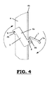
- the spring (5) is fitted with its supporting surface (6a) against that side of the flanged portion (4b) of the screen guide (4) which is facing away from the screen (2), in such a way that the resilient lips (7) extend alongside the screen guide (4) and on the side arranged to be facing in the screen device (1) towards the screen (2).
- the spring (5) is rotated against this flanged portion (4b) until the resilient lips extend in the longitudinal direction of the screen guide (4) along that side of the flanged portion (4b) which, in the assembled state, is facing in the screen device (1) towards the screen (2).
- the screen guide (4) is then fitted in the side guide (3) in such a way that the resilient lips (7) extend between the screen guide (4) and the side guide (3).
- the resilient lips (7) when fully relaxed, will stretch the screen (2) to a maximum, as illustrated in Figures 7 and 8 , whilst shocks can be absorbed by tensioning of the resilient lips (7) as illustrated in Figures 5 and 6 , after which the resilient lips (7), by automatically relaxing back again, ensure a maximal stretching of the screen (2).
Landscapes
- Engineering & Computer Science (AREA)
- Structural Engineering (AREA)
- Architecture (AREA)
- Civil Engineering (AREA)
- Operating, Guiding And Securing Of Roll- Type Closing Members (AREA)
- Overhead Projectors And Projection Screens (AREA)
Claims (10)
- Dispositif à rideau (1) comprenant un rideau (2) fixe ou enroulable vers le haut (relevable) et le bas (abaissable), des guides latéraux (3), dans lesquels des guide-rideau (4) sont montés, ces guide-rideau étant prévus pour la fixation du rideau ou le guidage du rideau relevable et abaissable (2) au cours de son mouvement d'enroulement vers le haut et vers le bas, et au moins un ressort (5) pour l'extension latérale élastique de ce rideau (2) dans les guides latéraux (3), caractérisé en ce que ledit ressort (5)• comprend une portion de fixation (6a, 6b, 6c), qui comprend au moins deux éléments de fixation (6b, 6c) aménagés pour enserrer au moins en partie le guide-rideau (4) afin de fixer le ressort (5) à ce guide-rideau (4), lesquels éléments de fixation (6b, 6c) sont aménagés sur cette portion de fixation (6a, 6b, 6c) de sorte qu'ils soient déplacés l'un par rapport à l'autre et sur les côtés opposés dans la direction longitudinale du guide-rideau (4), tandis qu'est présent, entre ces éléments de fixation (6b, 6c) dans ladite direction longitudinale, un espace intermédiaire qui est au moins aussi grand que la largeur du guide-rideau (4), qui s'étend dans une direction transversale au rideau (2) lorsque celui-ci est en extension ; et• comprend au moins une lèvre élastique (7) qui, à l'aide d'un élément de fixation (6b, 6c), est prévu sur la portion de fixation (6a, 6b, 6c), laquelle lèvre élastique (7) est aménagée pour s'étendre entre le guide-rideau (4) et le guide latéral (3) pour étendre le rideau (2) de manière élastique latéralement.
- Dispositif à rideau (1) selon la revendication 1, caractérisé en ce que ledit ressort comprend au moins deux lèvres élastiques (7) qui, à l'aide d'un élément de fixation (6b, 6c), sont chacune disposées sur la portion de fixation (6a, 6b, 6c) de sorte qu'elles soient aménagées sur cette portion de fixation (6a, 6b, 6c) afin qu'elles soient déplacées l'une par rapport à l'autre et sur les côtés opposés dans la direction longitudinale du guide-rideau (4), tandis qu'est présent, entre ces lèvres élastiques (7) dans ladite direction longitudinale, un espace intermédiaire qui est au moins aussi grand que la largeur du guide-rideau (4) qui s'étend dans une direction transversale au rideau (2) lorsque celui-ci est en extension, lesquelles lèvres élastiques (7) sont aménagées pour s'étendre entre le guide-rideau (4) et le guide latéral (3) pour étendre le rideau (2) de manière élastique latéralement.
- Dispositif à rideau (1) selon la revendication 1, caractérisé en ce que la portion de fixation (6a, 6b, 6c) du ressort (5) comprend :• une surface de support (6a) qui est aménagée pour reposer contre le côté du guide-rideau (4) qui est opposé au rideau (2) ;• au moins deux parties de raccordement (6b) dressées vers le haut en tant que partie des éléments de raccordement (6b, 6c), qui sont situées transversalement à la surface de support (6a) et sont aménagées pour s'étendre le long des côtés du guide-rideau (4) qui se raccordent au côté distant du rideau (2) et s'étendent dans une direction transversale à ce côté ;• au moins deux portions de support (6c) en tant que partie des éléments de raccordement (6b, 6c) à l'aide desquelles les lèvres élastiques (7) sont disposées sur les parties de raccordement (6b) dressées vers le haut, chacune de ces portions de support (6c) étant aménagée pour reposer contre un côté du guide-rideau (4) qui est tourné vers le rideau (2).
- Dispositif à rideau (1) selon l'une quelconque des revendications précédentes, caractérisé en ce que le guide-rideau (4) comprend une partie de guidage (4a) aménagée pour fixer le rideau (2) en mode de guidage, et une portion de bord (4b) aménagée pour monter, via celle-ci, le guide-rideau (4) dans le guide latéral (3), la portion de fixation (6a, 6b, 6c) du ressort (5) étant aménagée pour au moins en partie enserrer la portion de bord (4b) du guide-rideau (4) afin de fixer le ressort (5) à ce guide-rideau (4).
- Dispositif à rideau (1) selon l'une quelconque des revendications précédentes, caractérisé en ce que les lèvres élastiques (7), à l'état assemblé, s'écartent l'une de l'autre dans la direction longitudinale du guide-rideau (4).
- Dispositif à rideau (1) selon l'une quelconque des revendications précédentes, caractérisé en ce que les lèvres élastiques (7) comprennent, à leur extrémité libre, une partie rabattue (7a), qui est aménagée pour reposer contre le guide latéral (3) lorsque le ressort (5) s'étend entre le guide-rideau (4) et le guide latéral (3).
- Dispositif à rideau (1) selon l'une quelconque des revendications précédentes, caractérisé en ce que la portion de fixation (6a, 6b, 6c) dudit ressort (5) est pourvue d'au moins un crochet de blocage (8) prévu pour bloquer ce ressort (5), à l'état fixé, de manière fixe par rapport au guide-rideau (4).
- Dispositif à rideau (1) selon l'une quelconque des revendications précédentes, caractérisé en ce que ledit ressort (5) est produit dans une seule pièce de métal en feuille.
- Procédé pour placer un dit ressort (5) dans un dispositif à rideau (1) selon l'une quelconque des revendications 1 à 8, caractérisé en ce que ce procédé comprend les étapes suivantes :- étape 1 : ajustement du ressort (5) contre le côté du guide-rideau (4) qui est aménagé pour être, dans le dispositif à rideau (1), opposé au rideau (2), les éléments de fixation (6b, 6c) s'étendant le long du guide-rideau (4) et s'étendant sur le côté qui est aménagé pour être, dans le dispositif à rideau (1), tourné vers le rideau (2) ;- étape 2 : rotation du ressort (5) contre le guide-rideau (4) jusqu'à ce que la lèvre élastique (7) s'étende dans la direction longitudinale du guide-rideau (4) le long du côté du guide-rideau (4) qui, à l'état assemblé, est tourné vers le rideau (2) dans le dispositif à rideau (1) ; et- étape 3 : ajustement du guide-rideau (4), avec le ressort (5) fixé à celui-ci, dans le guide latéral (3) de sorte que la lèvre élastique (7) s'étende entre le guide-rideau (4) et le guide latéral (3).
- Procédé selon la revendication 9 pour placer un dit ressort (5) dans un dispositif à rideau (1) selon l'une quelconque des revendications 2 à 8, caractérisé en ce que ce procédé comprend les étapes suivantes :- étape 1 : ajustement du ressort (5) contre le côté du guide-rideau (4) qui est aménagé pour être, dans le dispositif à rideau (1), opposé au rideau (2), les lèvres élastiques (7) s'étendant le long du guide-rideau (4) et s'étendant sur le côté qui est aménagé pour être, dans le dispositif à rideau (1), tourné vers le rideau (2) ;- étape 2 : rotation du ressort (5) contre le guide-rideau (4) jusqu'à ce que les lèvres élastiques (7) s'étendent dans la direction longitudinale du guide-rideau (4) le long du côté du guide-rideau (4) qui, à l'état assemblé, est tourné vers le rideau (2) dans le dispositif à rideau (1) ; et- étape 3 : ajustement du guide-rideau (4), avec le ressort (5) fixé à celui-ci, dans le guide latéral (3) de sorte que les lèvres élastiques (7) s'étendent entre le guide-rideau (4) et le guide latéral (3).
Applications Claiming Priority (1)
| Application Number | Priority Date | Filing Date | Title |
|---|---|---|---|
| BE2008/0413A BE1018226A3 (nl) | 2008-07-24 | 2008-07-24 | Scherminrichting. |
Publications (3)
| Publication Number | Publication Date |
|---|---|
| EP2157275A2 EP2157275A2 (fr) | 2010-02-24 |
| EP2157275A3 EP2157275A3 (fr) | 2012-08-22 |
| EP2157275B1 true EP2157275B1 (fr) | 2013-02-13 |
Family
ID=40474925
Family Applications (1)
| Application Number | Title | Priority Date | Filing Date |
|---|---|---|---|
| EP09165372A Active EP2157275B1 (fr) | 2008-07-24 | 2009-07-14 | Dispositif de serrage pour un rideau enroulable guidé par rail |
Country Status (2)
| Country | Link |
|---|---|
| EP (1) | EP2157275B1 (fr) |
| BE (1) | BE1018226A3 (fr) |
Cited By (1)
| Publication number | Priority date | Publication date | Assignee | Title |
|---|---|---|---|---|
| KR101651522B1 (ko) * | 2015-08-07 | 2016-08-26 | 주식회사 신화인텍 | 암막 기능이 강화된 선박용 롤 스크린 장치 |
Families Citing this family (9)
| Publication number | Priority date | Publication date | Assignee | Title |
|---|---|---|---|---|
| DE102011118859B4 (de) * | 2011-11-18 | 2019-11-07 | Plastex Sa | Beschattungsvorrichtung |
| PL221436B1 (pl) | 2012-09-03 | 2016-04-29 | Fakro Pp Spółka Z Ograniczoną Odpowiedzialnością | Roleta przechylna z prowadnicami, zwłaszcza dla okna dachowego |
| BE1024265B1 (nl) | 2016-06-06 | 2018-01-16 | Renson Sunprotection Screens Nv | Scherminrichting |
| DE202017102736U1 (de) | 2017-05-08 | 2017-06-16 | Warema Renkhoff Se | Führungsschiene für eine Sonnenschutzanlage und entsprechende Sonnenschutzanlage |
| BE1026543B1 (nl) * | 2019-02-15 | 2020-03-10 | Renson Sunprotection Screens Nv | Zijgeleider voor scherminrichting |
| US11326395B2 (en) * | 2019-04-03 | 2022-05-10 | Michael Heissenberg | Retractable screen with horizontal tensioning track and vertical biasing member |
| EP3757343B1 (fr) | 2019-06-24 | 2021-05-05 | Roma Kg | Store vertical et ressort insert correspondant |
| EP4558695B1 (fr) | 2022-07-20 | 2026-04-29 | Corradi S.r.l. | Construction d'écran rétractable |
| CN115653476A (zh) * | 2022-10-11 | 2023-01-31 | 南京金星宇节能技术有限公司 | 一种宽幅电动织物卷帘系统及安装方法 |
Family Cites Families (3)
| Publication number | Priority date | Publication date | Assignee | Title |
|---|---|---|---|---|
| JPS62140894A (ja) | 1985-12-16 | 1987-06-24 | Sky Alum Co Ltd | 平版印刷版用アルミニウム合金支持体 |
| JP4820021B2 (ja) * | 2001-06-29 | 2011-11-24 | 立川ブラインド工業株式会社 | ロールブラインドのスクリーン案内装置 |
| DE102006023813B4 (de) | 2006-05-20 | 2008-10-02 | Daimler Ag | Rollosystem mit Querspannung |
-
2008
- 2008-07-24 BE BE2008/0413A patent/BE1018226A3/nl not_active IP Right Cessation
-
2009
- 2009-07-14 EP EP09165372A patent/EP2157275B1/fr active Active
Cited By (1)
| Publication number | Priority date | Publication date | Assignee | Title |
|---|---|---|---|---|
| KR101651522B1 (ko) * | 2015-08-07 | 2016-08-26 | 주식회사 신화인텍 | 암막 기능이 강화된 선박용 롤 스크린 장치 |
Also Published As
| Publication number | Publication date |
|---|---|
| EP2157275A2 (fr) | 2010-02-24 |
| EP2157275A3 (fr) | 2012-08-22 |
| BE1018226A3 (nl) | 2010-07-06 |
Similar Documents
| Publication | Publication Date | Title |
|---|---|---|
| EP2157275B1 (fr) | Dispositif de serrage pour un rideau enroulable guidé par rail | |
| EP2611974B1 (fr) | Barrière d'absorption des sons | |
| US9234367B2 (en) | T-post fence attachment system | |
| US20170274746A1 (en) | Tonneau cover system for a cargo box with side rail end plugs with external mounting extensions | |
| MX337994B (es) | Metodo para montar una pieza en una moldura perfilada, dispositivo de union intermedio para unir una pieza en una moldura perfilada, hoja de vidrio, y uso de este dispositivo. | |
| CA2754507C (fr) | Ensemble d'enseigne | |
| CA2653210A1 (fr) | Ensemble moustiquaire pour une fenetre ou une ouverture de porte | |
| EP3271540B1 (fr) | Dispositif d'écran | |
| WO2016102907A1 (fr) | Perfectionnements apportés ou se rapportant à des dispositifs de serrage | |
| WO2008020336A3 (fr) | Système de montage pour des panneaux de télécommunication | |
| WO2009012318A8 (fr) | Appareil de mise en tension de câble et procédé pour sécuriser une feuille sur un cadre | |
| JP6243242B2 (ja) | ベルトコンベアの安全柵 | |
| DE202007001697U1 (de) | Anschlussprofil, insbesondere Putzanschlussprofil | |
| AU2012264917B2 (en) | Battery fixing system for fixing at least one vehicle battery | |
| DE102011085188A1 (de) | Halteklemme und Montagesystem zum Befestigen eines oder mehrerer Flächenelemente an einem Gebäude | |
| EP3524766A1 (fr) | Dispositif de fixation d'un store | |
| KR20160140287A (ko) | 트램펄린 | |
| KR101598978B1 (ko) | 비닐하우스의 비닐고정 구조 | |
| FR2900671B1 (fr) | Construction temporaire et procede d'assemblage associe | |
| CN212839179U (zh) | 一种实现自适应调节绳索张紧状态的快卡式紧固件装置 | |
| EP2331347A1 (fr) | Procédé et système de montage d'une toile ou d'un drap sensiblement dans un plan | |
| FR2877286B1 (fr) | Dispositif de soutien, element de siege muni d'un tel dispositif et procede de montage d'un element de siege | |
| JP2013067933A (ja) | 高速安全性を有するヘルド枠 | |
| WO2008092428A3 (fr) | Élément de couverture et procédé de fixation dudit élément | |
| CN106246837B (zh) | 传动系统中的附件支撑架以及发电机系统 |
Legal Events
| Date | Code | Title | Description |
|---|---|---|---|
| PUAI | Public reference made under article 153(3) epc to a published international application that has entered the european phase |
Free format text: ORIGINAL CODE: 0009012 |
|
| AK | Designated contracting states |
Kind code of ref document: A2 Designated state(s): AT BE BG CH CY CZ DE DK EE ES FI FR GB GR HR HU IE IS IT LI LT LU LV MC MK MT NL NO PL PT RO SE SI SK SM TR |
|
| PUAL | Search report despatched |
Free format text: ORIGINAL CODE: 0009013 |
|
| AK | Designated contracting states |
Kind code of ref document: A3 Designated state(s): AT BE BG CH CY CZ DE DK EE ES FI FR GB GR HR HU IE IS IT LI LT LU LV MC MK MT NL NO PL PT RO SE SI SK SM TR |
|
| RIC1 | Information provided on ipc code assigned before grant |
Ipc: E06B 9/58 20060101AFI20120713BHEP |
|
| GRAP | Despatch of communication of intention to grant a patent |
Free format text: ORIGINAL CODE: EPIDOSNIGR1 |
|
| 17P | Request for examination filed |
Effective date: 20120904 |
|
| GRAP | Despatch of communication of intention to grant a patent |
Free format text: ORIGINAL CODE: EPIDOSNIGR1 |
|
| GRAS | Grant fee paid |
Free format text: ORIGINAL CODE: EPIDOSNIGR3 |
|
| GRAA | (expected) grant |
Free format text: ORIGINAL CODE: 0009210 |
|
| AK | Designated contracting states |
Kind code of ref document: B1 Designated state(s): AT BE BG CH CY CZ DE DK EE ES FI FR GB GR HR HU IE IS IT LI LT LU LV MC MK MT NL NO PL PT RO SE SI SK SM TR |
|
| REG | Reference to a national code |
Ref country code: GB Ref legal event code: FG4D |
|
| REG | Reference to a national code |
Ref country code: AT Ref legal event code: REF Ref document number: 596610 Country of ref document: AT Kind code of ref document: T Effective date: 20130215 |
|
| REG | Reference to a national code |
Ref country code: IE Ref legal event code: FG4D |
|
| REG | Reference to a national code |
Ref country code: DE Ref legal event code: R096 Ref document number: 602009013207 Country of ref document: DE Effective date: 20130411 |
|
| REG | Reference to a national code |
Ref country code: NL Ref legal event code: T3 |
|
| REG | Reference to a national code |
Ref country code: AT Ref legal event code: MK05 Ref document number: 596610 Country of ref document: AT Kind code of ref document: T Effective date: 20130213 |
|
| REG | Reference to a national code |
Ref country code: LT Ref legal event code: MG4D |
|
| PG25 | Lapsed in a contracting state [announced via postgrant information from national office to epo] |
Ref country code: ES Free format text: LAPSE BECAUSE OF FAILURE TO SUBMIT A TRANSLATION OF THE DESCRIPTION OR TO PAY THE FEE WITHIN THE PRESCRIBED TIME-LIMIT Effective date: 20130524 Ref country code: BG Free format text: LAPSE BECAUSE OF FAILURE TO SUBMIT A TRANSLATION OF THE DESCRIPTION OR TO PAY THE FEE WITHIN THE PRESCRIBED TIME-LIMIT Effective date: 20130513 Ref country code: NO Free format text: LAPSE BECAUSE OF FAILURE TO SUBMIT A TRANSLATION OF THE DESCRIPTION OR TO PAY THE FEE WITHIN THE PRESCRIBED TIME-LIMIT Effective date: 20130513 Ref country code: IS Free format text: LAPSE BECAUSE OF FAILURE TO SUBMIT A TRANSLATION OF THE DESCRIPTION OR TO PAY THE FEE WITHIN THE PRESCRIBED TIME-LIMIT Effective date: 20130613 Ref country code: AT Free format text: LAPSE BECAUSE OF FAILURE TO SUBMIT A TRANSLATION OF THE DESCRIPTION OR TO PAY THE FEE WITHIN THE PRESCRIBED TIME-LIMIT Effective date: 20130213 Ref country code: LT Free format text: LAPSE BECAUSE OF FAILURE TO SUBMIT A TRANSLATION OF THE DESCRIPTION OR TO PAY THE FEE WITHIN THE PRESCRIBED TIME-LIMIT Effective date: 20130213 Ref country code: SE Free format text: LAPSE BECAUSE OF FAILURE TO SUBMIT A TRANSLATION OF THE DESCRIPTION OR TO PAY THE FEE WITHIN THE PRESCRIBED TIME-LIMIT Effective date: 20130213 |
|
| PG25 | Lapsed in a contracting state [announced via postgrant information from national office to epo] |
Ref country code: FI Free format text: LAPSE BECAUSE OF FAILURE TO SUBMIT A TRANSLATION OF THE DESCRIPTION OR TO PAY THE FEE WITHIN THE PRESCRIBED TIME-LIMIT Effective date: 20130213 Ref country code: GR Free format text: LAPSE BECAUSE OF FAILURE TO SUBMIT A TRANSLATION OF THE DESCRIPTION OR TO PAY THE FEE WITHIN THE PRESCRIBED TIME-LIMIT Effective date: 20130514 Ref country code: PT Free format text: LAPSE BECAUSE OF FAILURE TO SUBMIT A TRANSLATION OF THE DESCRIPTION OR TO PAY THE FEE WITHIN THE PRESCRIBED TIME-LIMIT Effective date: 20130613 Ref country code: SI Free format text: LAPSE BECAUSE OF FAILURE TO SUBMIT A TRANSLATION OF THE DESCRIPTION OR TO PAY THE FEE WITHIN THE PRESCRIBED TIME-LIMIT Effective date: 20130213 Ref country code: LV Free format text: LAPSE BECAUSE OF FAILURE TO SUBMIT A TRANSLATION OF THE DESCRIPTION OR TO PAY THE FEE WITHIN THE PRESCRIBED TIME-LIMIT Effective date: 20130213 Ref country code: PL Free format text: LAPSE BECAUSE OF FAILURE TO SUBMIT A TRANSLATION OF THE DESCRIPTION OR TO PAY THE FEE WITHIN THE PRESCRIBED TIME-LIMIT Effective date: 20130213 |
|
| PG25 | Lapsed in a contracting state [announced via postgrant information from national office to epo] |
Ref country code: HR Free format text: LAPSE BECAUSE OF FAILURE TO SUBMIT A TRANSLATION OF THE DESCRIPTION OR TO PAY THE FEE WITHIN THE PRESCRIBED TIME-LIMIT Effective date: 20130213 |
|
| PG25 | Lapsed in a contracting state [announced via postgrant information from national office to epo] |
Ref country code: RO Free format text: LAPSE BECAUSE OF FAILURE TO SUBMIT A TRANSLATION OF THE DESCRIPTION OR TO PAY THE FEE WITHIN THE PRESCRIBED TIME-LIMIT Effective date: 20130213 Ref country code: CZ Free format text: LAPSE BECAUSE OF FAILURE TO SUBMIT A TRANSLATION OF THE DESCRIPTION OR TO PAY THE FEE WITHIN THE PRESCRIBED TIME-LIMIT Effective date: 20130213 Ref country code: EE Free format text: LAPSE BECAUSE OF FAILURE TO SUBMIT A TRANSLATION OF THE DESCRIPTION OR TO PAY THE FEE WITHIN THE PRESCRIBED TIME-LIMIT Effective date: 20130213 Ref country code: SK Free format text: LAPSE BECAUSE OF FAILURE TO SUBMIT A TRANSLATION OF THE DESCRIPTION OR TO PAY THE FEE WITHIN THE PRESCRIBED TIME-LIMIT Effective date: 20130213 Ref country code: DK Free format text: LAPSE BECAUSE OF FAILURE TO SUBMIT A TRANSLATION OF THE DESCRIPTION OR TO PAY THE FEE WITHIN THE PRESCRIBED TIME-LIMIT Effective date: 20130213 |
|
| PLBE | No opposition filed within time limit |
Free format text: ORIGINAL CODE: 0009261 |
|
| STAA | Information on the status of an ep patent application or granted ep patent |
Free format text: STATUS: NO OPPOSITION FILED WITHIN TIME LIMIT |
|
| PG25 | Lapsed in a contracting state [announced via postgrant information from national office to epo] |
Ref country code: IT Free format text: LAPSE BECAUSE OF FAILURE TO SUBMIT A TRANSLATION OF THE DESCRIPTION OR TO PAY THE FEE WITHIN THE PRESCRIBED TIME-LIMIT Effective date: 20130213 |
|
| 26N | No opposition filed |
Effective date: 20131114 |
|
| REG | Reference to a national code |
Ref country code: DE Ref legal event code: R097 Ref document number: 602009013207 Country of ref document: DE Effective date: 20131114 |
|
| PG25 | Lapsed in a contracting state [announced via postgrant information from national office to epo] |
Ref country code: MC Free format text: LAPSE BECAUSE OF FAILURE TO SUBMIT A TRANSLATION OF THE DESCRIPTION OR TO PAY THE FEE WITHIN THE PRESCRIBED TIME-LIMIT Effective date: 20130213 |
|
| REG | Reference to a national code |
Ref country code: CH Ref legal event code: PL |
|
| GBPC | Gb: european patent ceased through non-payment of renewal fee |
Effective date: 20130714 |
|
| REG | Reference to a national code |
Ref country code: IE Ref legal event code: MM4A |
|
| REG | Reference to a national code |
Ref country code: DE Ref legal event code: R119 Ref document number: 602009013207 Country of ref document: DE Effective date: 20140201 |
|
| REG | Reference to a national code |
Ref country code: FR Ref legal event code: ST Effective date: 20140331 |
|
| PG25 | Lapsed in a contracting state [announced via postgrant information from national office to epo] |
Ref country code: LI Free format text: LAPSE BECAUSE OF NON-PAYMENT OF DUE FEES Effective date: 20130731 Ref country code: GB Free format text: LAPSE BECAUSE OF NON-PAYMENT OF DUE FEES Effective date: 20130714 Ref country code: CH Free format text: LAPSE BECAUSE OF NON-PAYMENT OF DUE FEES Effective date: 20130731 Ref country code: DE Free format text: LAPSE BECAUSE OF NON-PAYMENT OF DUE FEES Effective date: 20140201 |
|
| PG25 | Lapsed in a contracting state [announced via postgrant information from national office to epo] |
Ref country code: FR Free format text: LAPSE BECAUSE OF NON-PAYMENT OF DUE FEES Effective date: 20130731 |
|
| PG25 | Lapsed in a contracting state [announced via postgrant information from national office to epo] |
Ref country code: IE Free format text: LAPSE BECAUSE OF NON-PAYMENT OF DUE FEES Effective date: 20130714 |
|
| PG25 | Lapsed in a contracting state [announced via postgrant information from national office to epo] |
Ref country code: SM Free format text: LAPSE BECAUSE OF FAILURE TO SUBMIT A TRANSLATION OF THE DESCRIPTION OR TO PAY THE FEE WITHIN THE PRESCRIBED TIME-LIMIT Effective date: 20130213 |
|
| PG25 | Lapsed in a contracting state [announced via postgrant information from national office to epo] |
Ref country code: CY Free format text: LAPSE BECAUSE OF FAILURE TO SUBMIT A TRANSLATION OF THE DESCRIPTION OR TO PAY THE FEE WITHIN THE PRESCRIBED TIME-LIMIT Effective date: 20130213 Ref country code: TR Free format text: LAPSE BECAUSE OF FAILURE TO SUBMIT A TRANSLATION OF THE DESCRIPTION OR TO PAY THE FEE WITHIN THE PRESCRIBED TIME-LIMIT Effective date: 20130213 Ref country code: MT Free format text: LAPSE BECAUSE OF FAILURE TO SUBMIT A TRANSLATION OF THE DESCRIPTION OR TO PAY THE FEE WITHIN THE PRESCRIBED TIME-LIMIT Effective date: 20130213 |
|
| PG25 | Lapsed in a contracting state [announced via postgrant information from national office to epo] |
Ref country code: LU Free format text: LAPSE BECAUSE OF NON-PAYMENT OF DUE FEES Effective date: 20130714 Ref country code: HU Free format text: LAPSE BECAUSE OF FAILURE TO SUBMIT A TRANSLATION OF THE DESCRIPTION OR TO PAY THE FEE WITHIN THE PRESCRIBED TIME-LIMIT; INVALID AB INITIO Effective date: 20090714 Ref country code: MK Free format text: LAPSE BECAUSE OF FAILURE TO SUBMIT A TRANSLATION OF THE DESCRIPTION OR TO PAY THE FEE WITHIN THE PRESCRIBED TIME-LIMIT Effective date: 20130213 |
|
| REG | Reference to a national code |
Ref country code: BE Ref legal event code: HC Owner name: RENSON, PAUL; BE Free format text: DETAILS ASSIGNMENT: CHANGE OF OWNER(S), CHANGEMENT DE NOM DU PROPRIETAIRE; FORMER OWNER NAME: RENSON, PAUL Effective date: 20200411 |
|
| P01 | Opt-out of the competence of the unified patent court (upc) registered |
Effective date: 20230327 |
|
| PGFP | Annual fee paid to national office [announced via postgrant information from national office to epo] |
Ref country code: NL Payment date: 20240719 Year of fee payment: 16 |
|
| REG | Reference to a national code |
Ref country code: BE Ref legal event code: HC Owner name: RENSON, PAUL; BE Free format text: DETAILS ASSIGNMENT: CHANGE OF OWNER(S), CHANGE OF OWNER(S) NAME; FORMER OWNER NAME: RENSON SUNPROTECTION-SCREENS NV Effective date: 20240909 |
|
| REG | Reference to a national code |
Ref country code: BE Ref legal event code: PD Owner name: RENSON, PAUL; BE Free format text: DETAILS ASSIGNMENT: CHANGE OF OWNER(S), ASSIGNMENT; FORMER OWNER NAME: RENSON OUTDOOR Effective date: 20240909 |
|
| PGFP | Annual fee paid to national office [announced via postgrant information from national office to epo] |
Ref country code: BE Payment date: 20250718 Year of fee payment: 17 |
|
| REG | Reference to a national code |
Ref country code: NL Ref legal event code: MM Effective date: 20250801 |
|
| PG25 | Lapsed in a contracting state [announced via postgrant information from national office to epo] |
Ref country code: NL Free format text: LAPSE BECAUSE OF NON-PAYMENT OF DUE FEES Effective date: 20250801 |