EP2157285A1 - Dispositif de turbine à gaz et procédé pour diriger l'ecoulement sur la turbine - Google Patents
Dispositif de turbine à gaz et procédé pour diriger l'ecoulement sur la turbine Download PDFInfo
- Publication number
- EP2157285A1 EP2157285A1 EP08014873A EP08014873A EP2157285A1 EP 2157285 A1 EP2157285 A1 EP 2157285A1 EP 08014873 A EP08014873 A EP 08014873A EP 08014873 A EP08014873 A EP 08014873A EP 2157285 A1 EP2157285 A1 EP 2157285A1
- Authority
- EP
- European Patent Office
- Prior art keywords
- inner housing
- turbine
- housing
- mixing
- gas turbine
- Prior art date
- Legal status (The legal status is an assumption and is not a legal conclusion. Google has not performed a legal analysis and makes no representation as to the accuracy of the status listed.)
- Withdrawn
Links
- 238000000034 method Methods 0.000 title claims abstract description 7
- 238000002485 combustion reaction Methods 0.000 claims abstract description 49
- 238000002156 mixing Methods 0.000 claims abstract description 42
- 239000000446 fuel Substances 0.000 claims abstract description 12
- 239000007789 gas Substances 0.000 claims description 69
- 230000010006 flight Effects 0.000 claims description 14
- 230000001133 acceleration Effects 0.000 claims description 5
- 230000015572 biosynthetic process Effects 0.000 claims description 2
- 230000006698 induction Effects 0.000 claims 1
- 238000004804 winding Methods 0.000 abstract 1
- 239000000567 combustion gas Substances 0.000 description 4
- 238000000926 separation method Methods 0.000 description 4
- 230000003628 erosive effect Effects 0.000 description 2
- 238000005457 optimization Methods 0.000 description 2
- 230000003647 oxidation Effects 0.000 description 2
- 238000007254 oxidation reaction Methods 0.000 description 2
- 101001121408 Homo sapiens L-amino-acid oxidase Proteins 0.000 description 1
- 102100026388 L-amino-acid oxidase Human genes 0.000 description 1
- 238000001816 cooling Methods 0.000 description 1
- 230000001419 dependent effect Effects 0.000 description 1
- 238000000265 homogenisation Methods 0.000 description 1
- 230000003716 rejuvenation Effects 0.000 description 1
Images

Classifications
-
- F—MECHANICAL ENGINEERING; LIGHTING; HEATING; WEAPONS; BLASTING
- F01—MACHINES OR ENGINES IN GENERAL; ENGINE PLANTS IN GENERAL; STEAM ENGINES
- F01D—NON-POSITIVE DISPLACEMENT MACHINES OR ENGINES, e.g. STEAM TURBINES
- F01D9/00—Stators
- F01D9/02—Nozzles; Nozzle boxes; Stator blades; Guide conduits, e.g. individual nozzles
- F01D9/023—Transition ducts between combustor cans and first stage of the turbine in gas-turbine engines; their cooling or sealings
-
- F—MECHANICAL ENGINEERING; LIGHTING; HEATING; WEAPONS; BLASTING
- F01—MACHINES OR ENGINES IN GENERAL; ENGINE PLANTS IN GENERAL; STEAM ENGINES
- F01D—NON-POSITIVE DISPLACEMENT MACHINES OR ENGINES, e.g. STEAM TURBINES
- F01D9/00—Stators
- F01D9/02—Nozzles; Nozzle boxes; Stator blades; Guide conduits, e.g. individual nozzles
- F01D9/026—Scrolls for radial machines or engines
-
- F—MECHANICAL ENGINEERING; LIGHTING; HEATING; WEAPONS; BLASTING
- F05—INDEXING SCHEMES RELATING TO ENGINES OR PUMPS IN VARIOUS SUBCLASSES OF CLASSES F01-F04
- F05D—INDEXING SCHEME FOR ASPECTS RELATING TO NON-POSITIVE-DISPLACEMENT MACHINES OR ENGINES, GAS-TURBINES OR JET-PROPULSION PLANTS
- F05D2250/00—Geometry
- F05D2250/10—Two-dimensional
- F05D2250/15—Two-dimensional spiral
-
- F—MECHANICAL ENGINEERING; LIGHTING; HEATING; WEAPONS; BLASTING
- F05—INDEXING SCHEMES RELATING TO ENGINES OR PUMPS IN VARIOUS SUBCLASSES OF CLASSES F01-F04
- F05D—INDEXING SCHEME FOR ASPECTS RELATING TO NON-POSITIVE-DISPLACEMENT MACHINES OR ENGINES, GAS-TURBINES OR JET-PROPULSION PLANTS
- F05D2250/00—Geometry
- F05D2250/20—Three-dimensional
- F05D2250/25—Three-dimensional helical
-
- F—MECHANICAL ENGINEERING; LIGHTING; HEATING; WEAPONS; BLASTING
- F05—INDEXING SCHEMES RELATING TO ENGINES OR PUMPS IN VARIOUS SUBCLASSES OF CLASSES F01-F04
- F05D—INDEXING SCHEME FOR ASPECTS RELATING TO NON-POSITIVE-DISPLACEMENT MACHINES OR ENGINES, GAS-TURBINES OR JET-PROPULSION PLANTS
- F05D2250/00—Geometry
- F05D2250/20—Three-dimensional
- F05D2250/29—Three-dimensional machined; miscellaneous
- F05D2250/292—Three-dimensional machined; miscellaneous tapered
-
- F—MECHANICAL ENGINEERING; LIGHTING; HEATING; WEAPONS; BLASTING
- F05—INDEXING SCHEMES RELATING TO ENGINES OR PUMPS IN VARIOUS SUBCLASSES OF CLASSES F01-F04
- F05D—INDEXING SCHEME FOR ASPECTS RELATING TO NON-POSITIVE-DISPLACEMENT MACHINES OR ENGINES, GAS-TURBINES OR JET-PROPULSION PLANTS
- F05D2250/00—Geometry
- F05D2250/30—Arrangement of components
- F05D2250/31—Arrangement of components according to the direction of their main axis or their axis of rotation
- F05D2250/313—Arrangement of components according to the direction of their main axis or their axis of rotation the axes being perpendicular to each other
Definitions
- the present invention relates to a gas turbine arrangement comprising at least one burner and a combustion chamber for combusting fuel, a mixing housing and an adjoining inner housing and a turbine arranged substantially in relation to the at least one burner, wherein the combustion exhaust gas resulting from the combustion of the fuel flows through the mixing housing in the inner housing, wherein the inner housing is configured such that the combustion exhaust gas is deflected in the inner housing in the direction of the turbine. Furthermore, the invention relates to a gas turbine and a method for Turbinenanströmung.
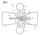
- a gas turbine plant 1 essentially comprises one or more combustion chambers 3 with burners 13 (cf. FIG. 2 ), in which a fuel is burned, a turbine 5, which are supplied to the hot and pressurized combustion exhaust gases from the combustion chambers 3 and in which the exhaust work under cooling and relaxation work and so put the turbine 5 in rotation, and a compressor 7, which is coupled to the turbine 5 via a shaft 12 which is surrounded by a hub 17, and via which the air necessary for the combustion is sucked in and compressed to a higher pressure.
- FIG. 1 shows such a gas turbine plant in a schematic view, wherein FIG1 shows a horizontal section through the plant.
- the combustion gases 2 flow in a direction which is substantially perpendicular to a rotation axis A of the turbine 5.
- a mixing housing 8 is arranged, which is followed by an inner housing 9 arranged in the interior of the gas turbine housing 2 on the turbine side.
- the inner housing 9 has the task to protect the surrounding components from heat and to redirect the emerging from the mixing housing 8 hot gases in the direction of the turbine.
- the gas in the inner housing 9 is deflected substantially by 90 ° degrees and then fed via a common annular space of the turbine. Due to the shape of the housing, there is no clear guidance of the two gas streams from the two silo separation chambers 3 to the turbine 5, that is to say the streams impinge on the hub 17 and are then distributed to the circulating space for turbine entry. This results in an inhomogeneous flow of the turbine 5. This is to be expected with performance losses.
- the first object is achieved by a gas turbine arrangement according to claim 1.
- the object related to the gas turbine is solved by specifying a gas turbine according to claim 10.
- the object related to the method is solved by claim 12.
- the dependent claims contain advantageous embodiments of the invention.
- a gas turbine arrangement comprises at least one burner and a combustion chamber for burning fuel, a mixing housing and an adjoining inner housing and a turbine arranged substantially perpendicular with respect to the at least one burner.
- the combustion exhaust gas produced by the combustion of the fuel flows through the mixing housing into the inner housing, wherein the inner housing is designed such that the combustion exhaust gas is deflected in the inner housing in the direction of the turbine. This is essentially a 90 degree deflection. Since, due to the shape of the housing no clear guidance of the gas flow is carried out on the turbine, resulting in an inhomogeneous flow. This results in poor performance values.
- the invention intervenes, and solves this long-standing problem by the at least inner casing has a turn.
- the at least one turn is helical.
- At least two mixing housings are present. These can be connected to two silo separation chambers. Preferably, at least two flights are provided which are connected to the two mixing housings.
- a clear leadership of the right and left Exhaust gas flow that is, the two streams that emerge from the different mixing housings, ensures the turbine.
- both exiting the mixing housing exhaust gas flows experience a clear flow to the turbine, which in turn improves the performance of the turbine.
- the at least two flights are tapered.
- the targeted rejuvenation of the two screw flights ensures that a constant acceleration of the exhaust gas from the mixing housing to the turbine is achieved over the entire path.
- a shaft is included, on which the turbine is arranged, wherein the inner housing has an inner housing hub, which is arranged substantially parallel to the shaft.
- the inner housing hub is at least approximately cylindrical.
- the turn in particular the worm gear in the mixing housing on its beginning and is formed to the inner housing hub.
- the turn especially the worm gear has the largest opening at the beginning and the smallest opening at the inner housing hub.
- a gas turbine which at least two substantially opposite each other Burner and combustion chambers and a respectively subsequent mixing housing and an adjoining inner housing, and further comprises a, arranged around a shaft inner housing hub.
- This can be especially known Silobrennschn.
- the inner housing is now formed by at least two screw threads, these starting at the mixing housings and ending at the inner housing hub, with the at least two screw threads tapering towards the inner housing hub.
- a clear guidance of the combustion exhaust gas streams emerging from the mixing housing is provided by the two screw flights.
- the two combustion exhaust gas streams are combined in a defined manner. Strömungsstauopi are thus prevented.
- a method of turbine flow comprising at least one burner and a combustion chamber in which fuel is burned to combustion exhaust gases, and a mixing housing and an adjoining inner housing for guiding the at least one combustion exhaust stream to a turbine substantially perpendicular to Flow direction of the combustion gases is arranged in the combustion chamber, wherein the combustion gases are deflected towards the turbine in the inner housing by means of a mecanicgephaseusenabe, wherein by means of a helical formation of the inner housing with at least one flight from the mixing housing to mecanicgephaseusenabe, wherein the at least one helical gear towards mecanicgephaseenabe tapered, a constant acceleration of the combustion exhaust gases is achieved until the turbine entry.
- a uniform flow over the entire circumference is generated at the turbine entrance, whereby an improvement of the turbine performance is achieved.
- gas turbine plant 1 An example of gas turbine plant 1 is in the FIG. 1 shown in a highly schematic representation.
- the gas turbine plant 1 comprises two silo combustion chambers 3, a turbine 5, a compressor 7, two mixing housings 8 and an inner housing 9.
- the silo combustion chambers 3 serve to burn a fuel, the hot exhaust gases 2 under high pressure being supplied via the mixing housings 8 and the inner housing 9 of the turbine 5 are supplied to drive these.
- the turbine 5 comprises stationary guide vanes 10 and rotor blades 11 fixedly connected to a shaft 12 rotatably mounted about an axis A.
- the hot exhaust gas 2 expanding in the turbine 5 transmits impulse to the shaft 12 via the rotor blades 11, causing them to rotate becomes.
- the shaft 12 may be roughly divided into three sections, namely a section carrying the blades 11 of the turbine 5, a rotor blade of the compressor 7 (not shown) and a section therebetween arranged shaft portions 16 in which no blades are arranged.
- the shaft 12 and the attached blades 11 form the so-called. Turbine rotor.
- the shaft 12 extends through the entire gas turbine plant (not fully shown) and drives the compressor 7 and a generator, not shown.
- the compressor 7 serves to compress air, which is then fed to the silo combustion chambers 3 for combustion.
- FIG. 2 shows a vertical section through the silo combustion chamber 3 with burners 13 a subsequent mixing housing 8 and an inner housing 9.
- the combustion chamber 3 as the burner 13 are vertical and are located at the top of the figure shown.
- the conical and curved mixing housing connects, which leads the combustion exhaust gases to the inner housing 9.
- the shaft 12 is of a wave protection jacket 15 (see. FIG. 3 ), which itself is surrounded by an inner housing hub 17 of the inner housing 9.
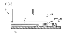
- FIG. 3 shows the inner housing with inner housing hub 17 (vertical section through the inner housing), in which the inner housing hub 17 of the inner housing 9 and a part of the wave protection jacket 15 can be seen.
- a guide vane 10 of the turbine 5 can be seen, which is opposite to the turbine-side opening 19 of the inner housing 9.
- the inner housing hub 17 and the shaft protection jacket 15 have substantially the shape of a hollow cylinder.
- the inner housing 9 serves to deflect the hot exhaust flowing from the mixing housings 8 into the inner housing 9 on the one hand and to distribute it as evenly as possible around the entire circumference of the turbine runner on the other hand. Here, the deflection is done by about 90 ° degrees.
- About a common annulus are the Gases then fed to the turbine 5. Due to the shape of the mixing housing, there is no clear guidance of the two exhaust gas streams to the turbine 5, that is to say the streams impinge on the hub 17 at the level of a parting line (not shown) and then distribute themselves on the circumferential space to the turbine inlet 20. This results An inhomogeneous flow to the turbine, which is expected to loss of performance.
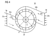
- FIG. 4 schematically shows the two mixing housing 8a, 8b with inventively designed inner housing 90 which consists of two screw threads 90a, 90b.
- inventively designed inner housing 90 which consists of two screw threads 90a, 90b.
- the inner housing 9 is therefore designed as an inventive inner housing 90, so to speak as a screw housing with two screw flights 90a, 90b. This ensures a clear guidance of the two exhaust gas streams 22a, 22b, which flow from the two mixing housings 8a, 8b through the inner housing 90 onto the turbine 5.
- the worm threads 90a, 90b are tapered, namely from the mixing housing with the largest openings of the screw threads 90a, 90b in the direction of the inner housing hub 17, where the check threads 90a, 90b end.
- the tapering of the two helical flights 90a, 90b is designed such that the two streams 22a, 22b experience a constant acceleration all the way to the turbine inlet 20, and thus a uniform flow onto the turbine 5, in particular on the first turbine guide vane. As a result, the combustion exhaust gas stream 22a, 22b is better diverted.
- the inner housing 90 as a screw housing with two screw flights 90a, 90b, a defined combination of two combustion exhaust gas flows onto a common annular space to the turbine inlet 20.
- flow distorts in the inner housing 90 and on the hub 17 are eliminated. whereby wear of the components is reduced by oxidation and erosion.
- Due to the inventive design of the inner housing 90 a uniform flow is generated over the entire circumference at the turbine inlet 20, whereby the turbine performance is improved.
Landscapes
- Engineering & Computer Science (AREA)
- Mechanical Engineering (AREA)
- General Engineering & Computer Science (AREA)
Priority Applications (1)
| Application Number | Priority Date | Filing Date | Title |
|---|---|---|---|
| EP08014873A EP2157285A1 (fr) | 2008-08-21 | 2008-08-21 | Dispositif de turbine à gaz et procédé pour diriger l'ecoulement sur la turbine |
Applications Claiming Priority (1)
| Application Number | Priority Date | Filing Date | Title |
|---|---|---|---|
| EP08014873A EP2157285A1 (fr) | 2008-08-21 | 2008-08-21 | Dispositif de turbine à gaz et procédé pour diriger l'ecoulement sur la turbine |
Publications (1)
| Publication Number | Publication Date |
|---|---|
| EP2157285A1 true EP2157285A1 (fr) | 2010-02-24 |
Family
ID=40791414
Family Applications (1)
| Application Number | Title | Priority Date | Filing Date |
|---|---|---|---|
| EP08014873A Withdrawn EP2157285A1 (fr) | 2008-08-21 | 2008-08-21 | Dispositif de turbine à gaz et procédé pour diriger l'ecoulement sur la turbine |
Country Status (1)
| Country | Link |
|---|---|
| EP (1) | EP2157285A1 (fr) |
Cited By (1)
| Publication number | Priority date | Publication date | Assignee | Title |
|---|---|---|---|---|
| WO2021192565A1 (fr) * | 2020-03-24 | 2021-09-30 | 株式会社豊田自動織機 | Turbocompresseur |
Citations (6)
| Publication number | Priority date | Publication date | Assignee | Title |
|---|---|---|---|---|
| US2801519A (en) * | 1951-02-17 | 1957-08-06 | Garrett Corp | Gas turbine motor scroll structure |
| EP0405730A1 (fr) * | 1989-06-28 | 1991-01-02 | ROLLS-ROYCE plc | Bloc de puissance à turbine à gaz |
| EP0493004A1 (fr) * | 1990-12-20 | 1992-07-01 | Honda Giken Kogyo Kabushiki Kaisha | Générateur de gaz pour une turbine à gaz |
| US6305172B1 (en) * | 1999-02-08 | 2001-10-23 | Samsung Aerospace Industries, Ltd. | Scroll for a combustion system |
| US20040035116A1 (en) * | 2002-08-23 | 2004-02-26 | Hans-O Jeske | Gas collection pipe carrying hot gas |
| US20050056015A1 (en) * | 2002-03-22 | 2005-03-17 | Peter Fledersbacher | Exhaust-gas turbocharger for an internal combustion engine |
-
2008
- 2008-08-21 EP EP08014873A patent/EP2157285A1/fr not_active Withdrawn
Patent Citations (6)
| Publication number | Priority date | Publication date | Assignee | Title |
|---|---|---|---|---|
| US2801519A (en) * | 1951-02-17 | 1957-08-06 | Garrett Corp | Gas turbine motor scroll structure |
| EP0405730A1 (fr) * | 1989-06-28 | 1991-01-02 | ROLLS-ROYCE plc | Bloc de puissance à turbine à gaz |
| EP0493004A1 (fr) * | 1990-12-20 | 1992-07-01 | Honda Giken Kogyo Kabushiki Kaisha | Générateur de gaz pour une turbine à gaz |
| US6305172B1 (en) * | 1999-02-08 | 2001-10-23 | Samsung Aerospace Industries, Ltd. | Scroll for a combustion system |
| US20050056015A1 (en) * | 2002-03-22 | 2005-03-17 | Peter Fledersbacher | Exhaust-gas turbocharger for an internal combustion engine |
| US20040035116A1 (en) * | 2002-08-23 | 2004-02-26 | Hans-O Jeske | Gas collection pipe carrying hot gas |
Cited By (2)
| Publication number | Priority date | Publication date | Assignee | Title |
|---|---|---|---|---|
| WO2021192565A1 (fr) * | 2020-03-24 | 2021-09-30 | 株式会社豊田自動織機 | Turbocompresseur |
| JP2021152337A (ja) * | 2020-03-24 | 2021-09-30 | 株式会社豊田自動織機 | ターボチャージャ |
Similar Documents
| Publication | Publication Date | Title |
|---|---|---|
| EP2179143B1 (fr) | Refroidissement de fente entre une paroi de chambre de combustion et une paroi de turbine d'une installation de turbine à gaz | |
| DE102010017733B4 (de) | Tesla-Turbine und Verfahren zur Wandlung von Strömungsenergie eines Fluids in kinetische Energie einer Welle einer Tesla-Turbine | |
| EP2167793B1 (fr) | Turbocompresseur a suralimentation de gaz d'échappement pour moteur à combustion interne | |
| EP1000224B1 (fr) | Repartition de l'air de refroidissement dans l'etage de turbine d'une turbine a gaz | |
| EP2532898A1 (fr) | Turbocompresseur axial | |
| EP2085695A1 (fr) | Buse à combustible dotée d'un canal à tourbillon et procédé de fabrication d'une buse à combustible | |
| EP1706597B1 (fr) | Turbine a gaz avec rotor axialement deplacable | |
| EP2818724A1 (fr) | Turbomachine, structure de circulation et procédé | |
| DE102007028742A1 (de) | Luftversorger, insbesondere für ein Luftversorgungssystem von Brennstoffzellen | |
| EP0532907B1 (fr) | Turbine axiale | |
| EP3245451A1 (fr) | Chambre de combustion pour turbine à gaz, délimitée par une paroi | |
| EP2505784A1 (fr) | Rotor pour une turbomachine et procédé associé de modernisation | |
| DE102012208263A1 (de) | Verdichtervorrichtung für eine Turbomaschine | |
| EP1744016A1 (fr) | Elément de carénage pour gaz chauds, chemise de protection de l'arbre et turbine à gaz | |
| DE102015012259A1 (de) | Turbinenrad für eine Turbine eines Abgasturboladers | |
| DE10255389A1 (de) | Niederdruckdampfturbine mit Mehrkanal-Diffusor | |
| EP2157285A1 (fr) | Dispositif de turbine à gaz et procédé pour diriger l'ecoulement sur la turbine | |
| DE102010044819B4 (de) | Axialturbine und ein Verfahren zum Abführen eines Stroms von einer Axialturbine | |
| EP3298285B1 (fr) | Aube directrice pour un diffuseur aubagé d'un compresseur centrifuge | |
| EP2225467B1 (fr) | Appareil de production de rotation et turbocompresseur équipé d'un tel appareil | |
| EP3321589A1 (fr) | Buse de carburant d'une turbine à gaz dotée du générateur de tourbillons | |
| EP2318664B1 (fr) | Dispositif de turbine à gaz avec conduit de transition non cylindrique | |
| EP1522696A2 (fr) | Compresseur axial avec injection d'eau pour turbine à gaz | |
| DE899298C (de) | Gasturbine fuer wechselnde Belastungen | |
| EP2157286A1 (fr) | Turbine à gaz avec conduit de mélange à angle et procédé pour diriger l'écoulement sur la turbine |
Legal Events
| Date | Code | Title | Description |
|---|---|---|---|
| PUAI | Public reference made under article 153(3) epc to a published international application that has entered the european phase |
Free format text: ORIGINAL CODE: 0009012 |
|
| AK | Designated contracting states |
Kind code of ref document: A1 Designated state(s): AT BE BG CH CY CZ DE DK EE ES FI FR GB GR HR HU IE IS IT LI LT LU LV MC MT NL NO PL PT RO SE SI SK TR |
|
| AX | Request for extension of the european patent |
Extension state: AL BA MK RS |
|
| AKY | No designation fees paid | ||
| STAA | Information on the status of an ep patent application or granted ep patent |
Free format text: STATUS: THE APPLICATION IS DEEMED TO BE WITHDRAWN |
|
| 18D | Application deemed to be withdrawn |
Effective date: 20100825 |
|
| REG | Reference to a national code |
Ref country code: DE Ref legal event code: R108 Effective date: 20110315 Ref country code: DE Ref legal event code: 8566 |