EP2157352A1 - Raccord, en particulier raccord de tuyaux - Google Patents
Raccord, en particulier raccord de tuyaux Download PDFInfo
- Publication number
- EP2157352A1 EP2157352A1 EP08014704A EP08014704A EP2157352A1 EP 2157352 A1 EP2157352 A1 EP 2157352A1 EP 08014704 A EP08014704 A EP 08014704A EP 08014704 A EP08014704 A EP 08014704A EP 2157352 A1 EP2157352 A1 EP 2157352A1
- Authority
- EP
- European Patent Office
- Prior art keywords
- coupling
- sleeve
- piece
- insertion groove
- coupling piece
- Prior art date
- Legal status (The legal status is an assumption and is not a legal conclusion. Google has not performed a legal analysis and makes no representation as to the accuracy of the status listed.)
- Granted
Links
- 230000008878 coupling Effects 0.000 title claims abstract description 180
- 238000010168 coupling process Methods 0.000 title claims abstract description 180
- 238000005859 coupling reaction Methods 0.000 title claims abstract description 180
- 238000003780 insertion Methods 0.000 claims abstract description 37
- 230000037431 insertion Effects 0.000 claims abstract description 37
- 238000010008 shearing Methods 0.000 claims description 11
- 230000004323 axial length Effects 0.000 claims description 10
- 230000005641 tunneling Effects 0.000 claims description 4
- 229910000831 Steel Inorganic materials 0.000 description 4
- 239000010959 steel Substances 0.000 description 4
- 238000009434 installation Methods 0.000 description 3
- 230000009471 action Effects 0.000 description 2
- 238000013459 approach Methods 0.000 description 2
- 230000013011 mating Effects 0.000 description 2
- 230000009467 reduction Effects 0.000 description 2
- 230000001174 ascending effect Effects 0.000 description 1
- 230000000903 blocking effect Effects 0.000 description 1
- 239000003245 coal Substances 0.000 description 1
- 230000000295 complement effect Effects 0.000 description 1
- 239000002131 composite material Substances 0.000 description 1
- 238000006073 displacement reaction Methods 0.000 description 1
- 230000000694 effects Effects 0.000 description 1
- 238000000605 extraction Methods 0.000 description 1
- 230000006872 improvement Effects 0.000 description 1
- 229910052500 inorganic mineral Inorganic materials 0.000 description 1
- 230000003993 interaction Effects 0.000 description 1
- 238000000034 method Methods 0.000 description 1
- 239000011707 mineral Substances 0.000 description 1
- 238000005065 mining Methods 0.000 description 1
- 230000008569 process Effects 0.000 description 1
- 230000000630 rising effect Effects 0.000 description 1
- 230000007704 transition Effects 0.000 description 1
Images

Classifications
-
- F—MECHANICAL ENGINEERING; LIGHTING; HEATING; WEAPONS; BLASTING
- F16—ENGINEERING ELEMENTS AND UNITS; GENERAL MEASURES FOR PRODUCING AND MAINTAINING EFFECTIVE FUNCTIONING OF MACHINES OR INSTALLATIONS; THERMAL INSULATION IN GENERAL
- F16L—PIPES; JOINTS OR FITTINGS FOR PIPES; SUPPORTS FOR PIPES, CABLES OR PROTECTIVE TUBING; MEANS FOR THERMAL INSULATION IN GENERAL
- F16L37/00—Couplings of the quick-acting type
- F16L37/08—Couplings of the quick-acting type in which the connection between abutting or axially overlapping ends is maintained by locking members
- F16L37/12—Couplings of the quick-acting type in which the connection between abutting or axially overlapping ends is maintained by locking members using hooks, pawls, or other movable or insertable locking members
- F16L37/14—Joints secured by inserting between mating surfaces an element, e.g. a piece of wire, a pin, a chain
- F16L37/142—Joints secured by inserting between mating surfaces an element, e.g. a piece of wire, a pin, a chain where the securing element is inserted tangentially
- F16L37/148—Joints secured by inserting between mating surfaces an element, e.g. a piece of wire, a pin, a chain where the securing element is inserted tangentially the securing element being flexible
Definitions
- the invention relates to a coupling, in particular pipe coupling for high-pressure pipes or high-pressure hoses, each provided with to be connected ends coupling sleeves, and with at least one coupling sleeves with the aid of at least two shearing elements coupling coupling piece in the coupling sleeve each engaging pin, wherein the respective pin and the Coupling sleeve to define a composed of two halves insertion slot for the associated shear element.
- the high-pressure pipes or high-pressure hoses usually serve to transport a hydraulic medium to a hydraulic machine, wherein pressurizations of more than 50 bar or even more than 100 bar are used. For this reason, any approach to reducing the wall thickness is prohibited.
- the invention is based on the technical problem of developing a generic coupling, in particular pipe coupling for high pressure pipes or high pressure hoses, so that the assembly is facilitated and at the same time a particularly functional and stable connection is provided.
- the plug-in pin and / or the coupling sleeve is equipped with an additional cone region or Zentrierkonus Colour.
- This conical area closes to the respective half of the Nuthdirector composed of the two Nuthdirectorn slot for the shear element, in the direction of slip or retraction of the coupling sleeve.
- bends of a few degrees (up to 10 °) between plug-in pin and coupling sleeve are observed at this point and expressly approved. This is in view of the limited installation conditions, especially in underground operation of particular importance and facilitates the coupling of individual pipes to a pipeline enormously.
- the pipes to be joined are equipped at their ends with the same coupling sleeves. So it is not necessary to distinguish, for example between mating end and socket end, as the DE 297 04 063 U1 expressly requires. Such a distinction is in the underground area practically not possible because a pipe can not be rotated or turned due to the cramped installation conditions. Consequently, the invention deliberately accesses identically formed coupling sleeves at the ends of the high-pressure pipes or high-pressure hoses to be connected. It is only necessary to connect these two ends to be connected medium-tight with the help of the intermediate coupling piece.
- a clamping region adjoins the already described cone region or centering cone region in the direction of displacement of the coupling sleeve.
- This clamping region is formed between the respective coupling sleeve and the coupling piece or adjusts itself by the advantageous interaction of an extension of the coupling sleeve with a clamping groove or insertion groove on the coupling piece.
- the reverse could be done. That means that the coupling piece with an extension is equipped, whereas the associated coupling sleeve has the mentioned clamping groove.
- the coupling sleeve is equipped with the extension, which engages in the clamping region or the clamping groove on the coupling piece.
- the coupling piece advantageously has a respective projection in the clamping region, which engages over an abutment region.
- a U-shaped overlap is thereby achieved in cross section, so that the clamping groove or insertion groove is U-shaped in cross-section. That is, the clamping groove is formed between the projection and the abutment portion on the coupling piece.
- the extension engages in the clamping groove.
- the coupling piece is adapted to fix two coupling sleeves, which are usually opposite each other with respect to a mirror axis, the coupling piece is regularly mirror-symmetrical in comparison to this axis arranged transversely to the longitudinal extent of the tubes or hoses.
- the coupling piece has a total of T-shaped stop for the respective adjacent coupling sleeves.
- This T-shaped stop is equipped with the U-shaped clamping grooves on both sides, in each of which engage the extensions of the associated coupling sleeves in the mounted position.
- the overall design is such that in the direction of the coupling sleeve to the insertion groove or the associated half half of the already mentioned cone region respectively Zentrierkonus Symposium follows and this follows in the direction of rest of the contact area of the clamping area, which is overlapped by the projection and in this way the clamping groove forms with the U-shaped cross-section for receiving the extension of the coupling sleeve.
- the insertion groove for the shear element is equipped with an evasion area.
- This evasive area ensures that the shear element can be inserted with play in the relevant insertion groove, however, at a corresponding load for the desired wedging with shearing action between the coupling piece and the associated spigot and the coupling sleeve provides.
- the escape area can be designed so that the insertion groove has an axial length which exceeds a diameter of the mostly cylindrical shear element.
- the shearing element is composed essentially of a soul of a plastic rope or a braided steel rope, which are threaded mostly cylindrical cylindrical body made of steel.
- the insertion groove now has a greater axial length than the diameter of the shear element or of the individual shear body of the same design. In most cases, the axial length of the insertion groove is approximately 1.2 to 1.5 times or more of the diameter of the relevant shear element or of the associated shear body used in most cases.
- the half-half in the respective coupling sleeve is equipped with a subsequent to a circular arc-like region inclined edge.
- the inclined edge has an ascending in the direction of the coupling sleeve rising edge.
- the shearing element is increasingly clamped in the insertion groove and provides with increasing wedge effect for a determination of the coupling sleeve on the coupling piece, if the coupling sleeve of the Move the coupling piece axially and / or radially away from one another in the pressure present in the high-pressure pipe or high-pressure hose.
- the coupling piece is designed mirror-symmetrically in comparison with the transversely arranged mirror axis.
- the coupling piece is regularly designed rotationally symmetrical compared to the pipe axis.
- the insertion groove for the extension of the coupling sleeve forms a Einschubringnut on the coupling piece.
- the T-shaped stop on the coupling piece is designed as a T-shaped ring stop.
- the half-half forms a respective annular groove in the coupling piece.
- the local Nuthdom is also designed as an annular groove and forms the engaging in the insertion groove extension an annular extension.
- the coupling piece is equipped with a respective end chamfer.
- This chamfer usually goes over into a chamfer angle of the same angle in the coupling sleeve. In this way, a uniform reduction in diameter with respect to the inner diameter of the high-pressure pipes or to be connected high-pressure hoses in the region of the coupling piece is achieved. This reduced diameter increases the end of the coupling piece again until the inner diameter of the connected pipe or hose is reached.
- the coupling piece is axially outwardly equipped compared to the shear element with a circumferential groove for a ring seal. This ensures that optionally occurring medium or hydraulic medium at abutting surfaces between the coupling sleeve and the coupling piece can not penetrate to the shear element or can penetrate.
- the invention is also the use of such a coupling for connecting high-pressure pipes, which are used to pressurize hydraulic machines. These hydraulic machines are advantageously tunneling machines in underground use. In fact, such tunneling machines are usually used in so-called shield tunneling in underground mineral extraction, in particular coal mining.
- a coupling in particular pipe coupling is provided, which can be produced in a particularly simple and functional manner.
- This is primarily provided by the cone region or centering cone region, which is advantageously formed on the respective plug-in pin.
- angular positions between the plug-in pin and the coupling sleeve to be attached thereto of a few degrees (up to 10 °) are permitted.
- the shearing element can be placed in the insertion groove formed from both Nuthpathn and introduced into this.
- the insertion groove for the shear element is equipped with an evasion region and regularly has an axial length which exceeds the diameter of the shear element or its shear body.
- the insertion of the shear element is made possible even with mutually verkantetem coupling piece and associated coupling sleeve.
- the shearing element comes perfectly to its wedging action, for which, among other things, the sloping flank in the half half of the coupling sleeve ensures, which in principle, of course, in the half-half in the coupling piece can be complementary or alternative.
- the main benefits are the main benefits.
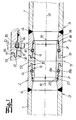
- a coupling is shown, which is particularly suitable for connecting high-pressure pipes 1.
- high pressure pipes 1 instead of the high pressure pipes 1 but also high pressure hoses can be connected to the still to be described coupling.
- High-pressure pipes 1 or high-pressure hoses in the context of the invention means such pipes or hoses which are acted upon by a medium which is usually even more than 100 bar under a high pressure of at least 50 bar.
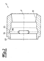
- coupling sleeves 2 which are connected to each end to be joined 3 of the high-pressure pipes 1.
- welded joints 4 are realized here, which of course is not mandatory.
- both the high-pressure pipes 1 and the coupling sleeves 2 are made of steel or high-strength steel. The same applies to a coupling piece 5 coupling the two coupling sleeves 2 together.
- the two coupling sleeves 2 at the ends 3 of the high-pressure pipes 1 to be connected are coupled to the coupling piece 5 with the aid of two shear elements 6.
- the coupling piece 5 has in each case in the coupling sleeve 2 engaging pin 7.
- the respective pin 7 and the coupling sleeve 2 define a two Nuthproblemn 8a, 8b composite insertion groove 8a, 8b for the associated shear element 6.
- the half-half 8a is formed on the coupling piece 5, whereas the half-half 8b of the insertion groove 8a, 8b is located on or in the respective coupling sleeve 2.
- the coupling piece 5 is configured mirror-symmetrically in comparison to a mirror axis S dividing the coupling piece 5.
- This mirror axis S extends substantially transversely to a pipe longitudinal axis A.
- the two high-pressure pipes 1 and the coupling sleeves 2 and the coupling piece 5 are configured rotationally symmetrical. Of course this is not a mandatory requirement.
- the half-half 8a in the plug-in pin 7 in the push-on direction R of the coupling sleeve 2 is transferred to the coupling piece 5 in a cone region 9, which in the Fig. 1 is shown enlarged.
- This conical region or centering cone region 9 has an inclined position of a few degrees, for example 5 ° or less, relative to the tube longitudinal axis A.
- An abutment region 10 on the coupling piece 5 or its plug-in pin 7 adjoins the conical region or centering cone region 9 in the push-on direction R.
- This contact area 10 in conjunction with a projection 11 forms a cross-sectionally U-shaped insertion slot 12 on the coupling piece 5.
- the insertion groove 8a, 8b for the shear element 6 formed by the two groove halves 8a, 8b has, according to the exemplary embodiment, an evading region 14.
- This escape region 14 of the insertion groove 8a, 8b for the shearing element 6 is composed essentially of two components.
- the insertion groove 8a, 8b has an axial length L which exceeds a diameter D of the shear element 6.
- the axial length L of the insertion groove 8a, 8b is approximately 1.2 to 1.5 times or more of the said diameter D of the shear element 6. That is, the following applies: L ⁇ 1 . 2 - 1 . 5 ⁇ D
- a sloping edge 15 is added, which adjoins a circular arc-like region 16, and within the half half 8b in the coupling sleeve 2.
- this inclined edge 15 with the circular arc-like region 16 but also in the half-half 8a of the coupling piece 5 may be formed.
- the escape area 14 is composed on the one hand of the increased axial length L compared to the diameter D of the shear element 6 and in addition the circular arc-like area 16 in conjunction with the inclined edge 15.
- the inclined edge 15 has an inclined position of approximately 20 ° in comparison to the tube longitudinal axis A.
- the respective insertion grooves 12 for the projections 13 are each formed opposite one another.
- the insertion grooves 12 with the projections 11 form a total of a T-shaped stop 17 for the here against each adjacent coupling sleeves 2.
- the coupling piece 5 is equipped with one end bevel 18, which merges into a bevel 19 of the same angle to the tube longitudinal axis A in the associated coupling sleeve 2.
- a circumferential groove 20 is still realized in the coupling piece 5, which is located axially outside compared to the shear element 6 and serves to receive a ring seal 21.
- the insertion groove 8a, 8b formed by the two groove halves 8a, 8b is equipped with an evading region 14, the associated shearing element 6 can be easily inserted into the insertion groove 8a, 8b even at a certain inclination or tilt between coupling sleeve 2 and coupling piece 5 and of course also remove.
Landscapes
- Engineering & Computer Science (AREA)
- General Engineering & Computer Science (AREA)
- Mechanical Engineering (AREA)
- Quick-Acting Or Multi-Walled Pipe Joints (AREA)
- Joints With Sleeves (AREA)
- Mutual Connection Of Rods And Tubes (AREA)
- Joints Allowing Movement (AREA)
- Rigid Pipes And Flexible Pipes (AREA)
- Non-Disconnectible Joints And Screw-Threaded Joints (AREA)
Priority Applications (4)
| Application Number | Priority Date | Filing Date | Title |
|---|---|---|---|
| DE502008002031T DE502008002031D1 (de) | 2008-08-19 | 2008-08-19 | Kupplung, insbesondere Rohrkupplung |
| AT08014704T ATE491909T1 (de) | 2008-08-19 | 2008-08-19 | Kupplung, insbesondere rohrkupplung |
| EP08014704A EP2157352B1 (fr) | 2008-08-19 | 2008-08-19 | Raccord, en particulier raccord de tuyaux |
| PCT/EP2009/004381 WO2010020303A1 (fr) | 2008-08-19 | 2009-06-17 | Raccord intérieur haute pression |
Applications Claiming Priority (1)
| Application Number | Priority Date | Filing Date | Title |
|---|---|---|---|
| EP08014704A EP2157352B1 (fr) | 2008-08-19 | 2008-08-19 | Raccord, en particulier raccord de tuyaux |
Publications (2)
| Publication Number | Publication Date |
|---|---|
| EP2157352A1 true EP2157352A1 (fr) | 2010-02-24 |
| EP2157352B1 EP2157352B1 (fr) | 2010-12-15 |
Family
ID=40385502
Family Applications (1)
| Application Number | Title | Priority Date | Filing Date |
|---|---|---|---|
| EP08014704A Not-in-force EP2157352B1 (fr) | 2008-08-19 | 2008-08-19 | Raccord, en particulier raccord de tuyaux |
Country Status (4)
| Country | Link |
|---|---|
| EP (1) | EP2157352B1 (fr) |
| AT (1) | ATE491909T1 (fr) |
| DE (1) | DE502008002031D1 (fr) |
| WO (1) | WO2010020303A1 (fr) |
Cited By (2)
| Publication number | Priority date | Publication date | Assignee | Title |
|---|---|---|---|---|
| US20140183861A1 (en) * | 2012-12-31 | 2014-07-03 | John M. Coogan | Flush joint pipe |
| US10443766B2 (en) | 2015-06-05 | 2019-10-15 | North American Specialty Products Llc | System, method and apparatus for restrained pipe joint |
Families Citing this family (2)
| Publication number | Priority date | Publication date | Assignee | Title |
|---|---|---|---|---|
| DE202010003585U1 (de) | 2010-03-12 | 2010-08-05 | Karl Hamacher Gmbh | Kupplung, insbesondere Rohrkupplung für Hochdruckschläuche oder Hochdruckrohre |
| DE202013102274U1 (de) | 2013-05-24 | 2013-06-06 | Hochdrucktechnik Füsser GmbH | Kupplung, insbesondere Rohrkupplung |
Citations (6)
| Publication number | Priority date | Publication date | Assignee | Title |
|---|---|---|---|---|
| US5255945A (en) * | 1991-12-02 | 1993-10-26 | Solinst Canada Limited | End-to-end jointing system for tubes and pipes |
| DE29704063U1 (de) | 1997-03-06 | 1997-05-07 | Rehau Ag + Co, 95111 Rehau | Rohrverbindung |
| DE10146186C1 (de) * | 2001-09-19 | 2003-03-06 | Rwe Rheinbraun Ag | Scherelement |
| US20030234536A1 (en) * | 2002-06-20 | 2003-12-25 | Riedy Charles H. | Bell and spigot joint with locking strap |
| DE102005001993A1 (de) | 2005-01-15 | 2006-07-27 | Röhrenwerk Kupferdreh Carl Hamm GmbH | Steckmuffenrohrverbindung für insbesondere Steigleitungsrohre |
| EP1865244A2 (fr) | 2006-06-08 | 2007-12-12 | Karl Hamacher GmbH | Raccord, notamment raccord de tuyaux ou de conduites haute pression |
Family Cites Families (4)
| Publication number | Priority date | Publication date | Assignee | Title |
|---|---|---|---|---|
| DE1914465A1 (de) * | 1969-03-21 | 1970-10-01 | Hemscheidt Maschf Hermann | Verbindungsklammer |
| US4431218A (en) * | 1982-02-05 | 1984-02-14 | Dayco Corporation | Fluid coupling and method of making same |
| US4603886A (en) * | 1984-03-26 | 1986-08-05 | Vetco Offshore, Inc. | Snap type pipe connector |
| SE8505685L (sv) * | 1985-12-02 | 1987-06-03 | Stig Westman | Anordning for hopskarvning av ror |
-
2008
- 2008-08-19 EP EP08014704A patent/EP2157352B1/fr not_active Not-in-force
- 2008-08-19 DE DE502008002031T patent/DE502008002031D1/de active Active
- 2008-08-19 AT AT08014704T patent/ATE491909T1/de active
-
2009
- 2009-06-17 WO PCT/EP2009/004381 patent/WO2010020303A1/fr not_active Ceased
Patent Citations (6)
| Publication number | Priority date | Publication date | Assignee | Title |
|---|---|---|---|---|
| US5255945A (en) * | 1991-12-02 | 1993-10-26 | Solinst Canada Limited | End-to-end jointing system for tubes and pipes |
| DE29704063U1 (de) | 1997-03-06 | 1997-05-07 | Rehau Ag + Co, 95111 Rehau | Rohrverbindung |
| DE10146186C1 (de) * | 2001-09-19 | 2003-03-06 | Rwe Rheinbraun Ag | Scherelement |
| US20030234536A1 (en) * | 2002-06-20 | 2003-12-25 | Riedy Charles H. | Bell and spigot joint with locking strap |
| DE102005001993A1 (de) | 2005-01-15 | 2006-07-27 | Röhrenwerk Kupferdreh Carl Hamm GmbH | Steckmuffenrohrverbindung für insbesondere Steigleitungsrohre |
| EP1865244A2 (fr) | 2006-06-08 | 2007-12-12 | Karl Hamacher GmbH | Raccord, notamment raccord de tuyaux ou de conduites haute pression |
Cited By (4)
| Publication number | Priority date | Publication date | Assignee | Title |
|---|---|---|---|---|
| US20140183861A1 (en) * | 2012-12-31 | 2014-07-03 | John M. Coogan | Flush joint pipe |
| US9200732B2 (en) | 2012-12-31 | 2015-12-01 | North American Specialty Products Llc | Flush joint pipe |
| US9568120B2 (en) * | 2012-12-31 | 2017-02-14 | North American Specialty Products Llc | Flush joint pipe |
| US10443766B2 (en) | 2015-06-05 | 2019-10-15 | North American Specialty Products Llc | System, method and apparatus for restrained pipe joint |
Also Published As
| Publication number | Publication date |
|---|---|
| EP2157352B1 (fr) | 2010-12-15 |
| ATE491909T1 (de) | 2011-01-15 |
| WO2010020303A1 (fr) | 2010-02-25 |
| DE502008002031D1 (de) | 2011-01-27 |
Similar Documents
| Publication | Publication Date | Title |
|---|---|---|
| EP2354615B1 (fr) | Dispositif de sécurisation d'un raccordement de conduite de fluide | |
| EP0501404B1 (fr) | Dispositif de raccordement pour tuyaux en matière plastique et méthode pour raccorder un tuyau en matière plastique | |
| EP2035736B1 (fr) | Raccord par manchon | |
| DE102007025787A1 (de) | Rohrkupplung, Verfahren zum Rohrkuppeln, und zur Selbstreinigung von Kupplungshälften beim Rohrkuppeln | |
| EP2565510A2 (fr) | Dispositif de raccord de tuyaux à double paroi | |
| EP1984666B1 (fr) | Dispositif de connexion de tuyaux | |
| EP2694856A1 (fr) | Système de vissage résistant à de hautes pressions, destiné à des tubes ou des tuyaux dotés d'un filet conique | |
| EP2157352B1 (fr) | Raccord, en particulier raccord de tuyaux | |
| DE102008058042B4 (de) | Rohrkupplung für Rohre | |
| EP2295842B1 (fr) | Raccord de tuyau destiné à raccorder de manière étanche une extrémité d'un tuyau en matière flexible | |
| EP0340499A1 (fr) | Raccord de tuyaux | |
| EP3683481A1 (fr) | Raccord et pièce d'extension pour conduites | |
| DE102011053208A1 (de) | Verbindungsanordnung für Fluidleitungen mit einer weiteren fluidführenden Komponente | |
| EP1865244B1 (fr) | Raccord, notamment raccord de tuyaux ou de conduites haute pression | |
| DE102008047003A1 (de) | Nicht lösbare Rohrleitungsverbindung | |
| DE10007369A1 (de) | Rohrkupplung | |
| WO2009062748A1 (fr) | Raccord, en particulier raccord pour tuyaux | |
| DE102008021312B4 (de) | Vorrichtung zum lösbaren Verbinden mit einem Ende einer röhrenartigen Leitung, insbesondere mit einem biegesteifen Rohr | |
| EP1046854A2 (fr) | Raccord à manchon pour connecter deux tuyaux et un dispositif de verrouillage pour un raccord à manchon | |
| EP3280943B1 (fr) | Dispositif permettant de relier une conduite de raccordement à une conduite rénovée | |
| EP1245888B1 (fr) | Adaptateur de position pour des connections de tuyaux et câbles | |
| DE2016440B2 (fr) | ||
| DE8805742U1 (de) | Rohrverbindung | |
| DE102007013560B4 (de) | Einstellbarer Segmentbogen | |
| WO2016139004A1 (fr) | Système de liaison |
Legal Events
| Date | Code | Title | Description |
|---|---|---|---|
| PUAI | Public reference made under article 153(3) epc to a published international application that has entered the european phase |
Free format text: ORIGINAL CODE: 0009012 |
|
| AK | Designated contracting states |
Kind code of ref document: A1 Designated state(s): AT BE BG CH CY CZ DE DK EE ES FI FR GB GR HR HU IE IS IT LI LT LU LV MC MT NL NO PL PT RO SE SI SK TR |
|
| AX | Request for extension of the european patent |
Extension state: AL BA MK RS |
|
| 17P | Request for examination filed |
Effective date: 20100316 |
|
| GRAP | Despatch of communication of intention to grant a patent |
Free format text: ORIGINAL CODE: EPIDOSNIGR1 |
|
| GRAS | Grant fee paid |
Free format text: ORIGINAL CODE: EPIDOSNIGR3 |
|
| AKX | Designation fees paid |
Designated state(s): AT BE BG CH CY CZ DE DK EE ES FI FR GB GR HR HU IE IS IT LI LT LU LV MC MT NL NO PL PT RO SE SI SK TR |
|
| GRAA | (expected) grant |
Free format text: ORIGINAL CODE: 0009210 |
|
| AK | Designated contracting states |
Kind code of ref document: B1 Designated state(s): AT BE BG CH CY CZ DE DK EE ES FI FR GB GR HR HU IE IS IT LI LT LU LV MC MT NL NO PL PT RO SE SI SK TR |
|
| REG | Reference to a national code |
Ref country code: CH Ref legal event code: EP Ref country code: GB Ref legal event code: FG4D Free format text: NOT ENGLISH |
|
| REG | Reference to a national code |
Ref country code: IE Ref legal event code: FG4D |
|
| REF | Corresponds to: |
Ref document number: 502008002031 Country of ref document: DE Date of ref document: 20110127 Kind code of ref document: P |
|
| REG | Reference to a national code |
Ref country code: NL Ref legal event code: VDEP Effective date: 20101215 |
|
| PG25 | Lapsed in a contracting state [announced via postgrant information from national office to epo] |
Ref country code: NO Free format text: LAPSE BECAUSE OF FAILURE TO SUBMIT A TRANSLATION OF THE DESCRIPTION OR TO PAY THE FEE WITHIN THE PRESCRIBED TIME-LIMIT Effective date: 20110315 Ref country code: LT Free format text: LAPSE BECAUSE OF FAILURE TO SUBMIT A TRANSLATION OF THE DESCRIPTION OR TO PAY THE FEE WITHIN THE PRESCRIBED TIME-LIMIT Effective date: 20101215 |
|
| LTIE | Lt: invalidation of european patent or patent extension |
Effective date: 20101215 |
|
| PG25 | Lapsed in a contracting state [announced via postgrant information from national office to epo] |
Ref country code: FI Free format text: LAPSE BECAUSE OF FAILURE TO SUBMIT A TRANSLATION OF THE DESCRIPTION OR TO PAY THE FEE WITHIN THE PRESCRIBED TIME-LIMIT Effective date: 20101215 Ref country code: BG Free format text: LAPSE BECAUSE OF FAILURE TO SUBMIT A TRANSLATION OF THE DESCRIPTION OR TO PAY THE FEE WITHIN THE PRESCRIBED TIME-LIMIT Effective date: 20110315 Ref country code: CY Free format text: LAPSE BECAUSE OF FAILURE TO SUBMIT A TRANSLATION OF THE DESCRIPTION OR TO PAY THE FEE WITHIN THE PRESCRIBED TIME-LIMIT Effective date: 20101215 Ref country code: HR Free format text: LAPSE BECAUSE OF FAILURE TO SUBMIT A TRANSLATION OF THE DESCRIPTION OR TO PAY THE FEE WITHIN THE PRESCRIBED TIME-LIMIT Effective date: 20101215 Ref country code: SI Free format text: LAPSE BECAUSE OF FAILURE TO SUBMIT A TRANSLATION OF THE DESCRIPTION OR TO PAY THE FEE WITHIN THE PRESCRIBED TIME-LIMIT Effective date: 20101215 Ref country code: LV Free format text: LAPSE BECAUSE OF FAILURE TO SUBMIT A TRANSLATION OF THE DESCRIPTION OR TO PAY THE FEE WITHIN THE PRESCRIBED TIME-LIMIT Effective date: 20101215 Ref country code: NL Free format text: LAPSE BECAUSE OF FAILURE TO SUBMIT A TRANSLATION OF THE DESCRIPTION OR TO PAY THE FEE WITHIN THE PRESCRIBED TIME-LIMIT Effective date: 20101215 Ref country code: SE Free format text: LAPSE BECAUSE OF FAILURE TO SUBMIT A TRANSLATION OF THE DESCRIPTION OR TO PAY THE FEE WITHIN THE PRESCRIBED TIME-LIMIT Effective date: 20101215 |
|
| REG | Reference to a national code |
Ref country code: IE Ref legal event code: FD4D |
|
| PG25 | Lapsed in a contracting state [announced via postgrant information from national office to epo] |
Ref country code: CZ Free format text: LAPSE BECAUSE OF FAILURE TO SUBMIT A TRANSLATION OF THE DESCRIPTION OR TO PAY THE FEE WITHIN THE PRESCRIBED TIME-LIMIT Effective date: 20101215 Ref country code: IS Free format text: LAPSE BECAUSE OF FAILURE TO SUBMIT A TRANSLATION OF THE DESCRIPTION OR TO PAY THE FEE WITHIN THE PRESCRIBED TIME-LIMIT Effective date: 20110415 Ref country code: EE Free format text: LAPSE BECAUSE OF FAILURE TO SUBMIT A TRANSLATION OF THE DESCRIPTION OR TO PAY THE FEE WITHIN THE PRESCRIBED TIME-LIMIT Effective date: 20101215 Ref country code: PT Free format text: LAPSE BECAUSE OF FAILURE TO SUBMIT A TRANSLATION OF THE DESCRIPTION OR TO PAY THE FEE WITHIN THE PRESCRIBED TIME-LIMIT Effective date: 20110415 Ref country code: GR Free format text: LAPSE BECAUSE OF FAILURE TO SUBMIT A TRANSLATION OF THE DESCRIPTION OR TO PAY THE FEE WITHIN THE PRESCRIBED TIME-LIMIT Effective date: 20110316 Ref country code: IE Free format text: LAPSE BECAUSE OF FAILURE TO SUBMIT A TRANSLATION OF THE DESCRIPTION OR TO PAY THE FEE WITHIN THE PRESCRIBED TIME-LIMIT Effective date: 20101215 Ref country code: ES Free format text: LAPSE BECAUSE OF FAILURE TO SUBMIT A TRANSLATION OF THE DESCRIPTION OR TO PAY THE FEE WITHIN THE PRESCRIBED TIME-LIMIT Effective date: 20110326 |
|
| PG25 | Lapsed in a contracting state [announced via postgrant information from national office to epo] |
Ref country code: PL Free format text: LAPSE BECAUSE OF FAILURE TO SUBMIT A TRANSLATION OF THE DESCRIPTION OR TO PAY THE FEE WITHIN THE PRESCRIBED TIME-LIMIT Effective date: 20101215 Ref country code: RO Free format text: LAPSE BECAUSE OF FAILURE TO SUBMIT A TRANSLATION OF THE DESCRIPTION OR TO PAY THE FEE WITHIN THE PRESCRIBED TIME-LIMIT Effective date: 20101215 Ref country code: SK Free format text: LAPSE BECAUSE OF FAILURE TO SUBMIT A TRANSLATION OF THE DESCRIPTION OR TO PAY THE FEE WITHIN THE PRESCRIBED TIME-LIMIT Effective date: 20101215 |
|
| PLBE | No opposition filed within time limit |
Free format text: ORIGINAL CODE: 0009261 |
|
| STAA | Information on the status of an ep patent application or granted ep patent |
Free format text: STATUS: NO OPPOSITION FILED WITHIN TIME LIMIT |
|
| PG25 | Lapsed in a contracting state [announced via postgrant information from national office to epo] |
Ref country code: DK Free format text: LAPSE BECAUSE OF FAILURE TO SUBMIT A TRANSLATION OF THE DESCRIPTION OR TO PAY THE FEE WITHIN THE PRESCRIBED TIME-LIMIT Effective date: 20101215 |
|
| 26N | No opposition filed |
Effective date: 20110916 |
|
| PG25 | Lapsed in a contracting state [announced via postgrant information from national office to epo] |
Ref country code: MT Free format text: LAPSE BECAUSE OF FAILURE TO SUBMIT A TRANSLATION OF THE DESCRIPTION OR TO PAY THE FEE WITHIN THE PRESCRIBED TIME-LIMIT Effective date: 20101215 Ref country code: IT Free format text: LAPSE BECAUSE OF FAILURE TO SUBMIT A TRANSLATION OF THE DESCRIPTION OR TO PAY THE FEE WITHIN THE PRESCRIBED TIME-LIMIT Effective date: 20101215 |
|
| REG | Reference to a national code |
Ref country code: DE Ref legal event code: R097 Ref document number: 502008002031 Country of ref document: DE Effective date: 20110916 |
|
| BERE | Be: lapsed |
Owner name: KARL HAMACHER G.M.B.H. Effective date: 20110831 |
|
| PG25 | Lapsed in a contracting state [announced via postgrant information from national office to epo] |
Ref country code: MC Free format text: LAPSE BECAUSE OF NON-PAYMENT OF DUE FEES Effective date: 20110831 |
|
| REG | Reference to a national code |
Ref country code: FR Ref legal event code: ST Effective date: 20120430 |
|
| PG25 | Lapsed in a contracting state [announced via postgrant information from national office to epo] |
Ref country code: BE Free format text: LAPSE BECAUSE OF NON-PAYMENT OF DUE FEES Effective date: 20110831 |
|
| REG | Reference to a national code |
Ref country code: DE Ref legal event code: R119 Ref document number: 502008002031 Country of ref document: DE Effective date: 20120301 |
|
| PG25 | Lapsed in a contracting state [announced via postgrant information from national office to epo] |
Ref country code: FR Free format text: LAPSE BECAUSE OF NON-PAYMENT OF DUE FEES Effective date: 20110831 |
|
| REG | Reference to a national code |
Ref country code: CH Ref legal event code: PL |
|
| GBPC | Gb: european patent ceased through non-payment of renewal fee |
Effective date: 20120819 |
|
| PG25 | Lapsed in a contracting state [announced via postgrant information from national office to epo] |
Ref country code: CH Free format text: LAPSE BECAUSE OF NON-PAYMENT OF DUE FEES Effective date: 20120831 Ref country code: LI Free format text: LAPSE BECAUSE OF NON-PAYMENT OF DUE FEES Effective date: 20120831 |
|
| PG25 | Lapsed in a contracting state [announced via postgrant information from national office to epo] |
Ref country code: LU Free format text: LAPSE BECAUSE OF NON-PAYMENT OF DUE FEES Effective date: 20110819 |
|
| PG25 | Lapsed in a contracting state [announced via postgrant information from national office to epo] |
Ref country code: DE Free format text: LAPSE BECAUSE OF NON-PAYMENT OF DUE FEES Effective date: 20120301 |
|
| PG25 | Lapsed in a contracting state [announced via postgrant information from national office to epo] |
Ref country code: GB Free format text: LAPSE BECAUSE OF NON-PAYMENT OF DUE FEES Effective date: 20120819 |
|
| PG25 | Lapsed in a contracting state [announced via postgrant information from national office to epo] |
Ref country code: TR Free format text: LAPSE BECAUSE OF FAILURE TO SUBMIT A TRANSLATION OF THE DESCRIPTION OR TO PAY THE FEE WITHIN THE PRESCRIBED TIME-LIMIT Effective date: 20101215 |
|
| PG25 | Lapsed in a contracting state [announced via postgrant information from national office to epo] |
Ref country code: HU Free format text: LAPSE BECAUSE OF FAILURE TO SUBMIT A TRANSLATION OF THE DESCRIPTION OR TO PAY THE FEE WITHIN THE PRESCRIBED TIME-LIMIT Effective date: 20101215 |
|
| REG | Reference to a national code |
Ref country code: AT Ref legal event code: MM01 Ref document number: 491909 Country of ref document: AT Kind code of ref document: T Effective date: 20130819 |
|
| PG25 | Lapsed in a contracting state [announced via postgrant information from national office to epo] |
Ref country code: AT Free format text: LAPSE BECAUSE OF NON-PAYMENT OF DUE FEES Effective date: 20130819 |