EP2157358A2 - Dispositif d'éclairage à semi-conducteur - Google Patents
Dispositif d'éclairage à semi-conducteur Download PDFInfo
- Publication number
- EP2157358A2 EP2157358A2 EP09166343A EP09166343A EP2157358A2 EP 2157358 A2 EP2157358 A2 EP 2157358A2 EP 09166343 A EP09166343 A EP 09166343A EP 09166343 A EP09166343 A EP 09166343A EP 2157358 A2 EP2157358 A2 EP 2157358A2
- Authority
- EP
- European Patent Office
- Prior art keywords
- lighting device
- light source
- semiconductor light
- led
- cover
- Prior art date
- Legal status (The legal status is an assumption and is not a legal conclusion. Google has not performed a legal analysis and makes no representation as to the accuracy of the status listed.)
- Withdrawn
Links
- 239000004065 semiconductor Substances 0.000 title claims abstract description 28
- 239000000919 ceramic Substances 0.000 claims abstract description 10
- 239000004033 plastic Substances 0.000 claims abstract description 8
- 239000002131 composite material Substances 0.000 claims description 12
- 238000002955 isolation Methods 0.000 claims description 4
- 230000003287 optical effect Effects 0.000 claims description 3
- 238000009413 insulation Methods 0.000 abstract description 13
- 150000001875 compounds Chemical class 0.000 abstract 1
- 229910052751 metal Inorganic materials 0.000 description 15
- 239000002184 metal Substances 0.000 description 15
- 239000000758 substrate Substances 0.000 description 13
- 239000002985 plastic film Substances 0.000 description 9
- 229920006255 plastic film Polymers 0.000 description 9
- 238000010292 electrical insulation Methods 0.000 description 6
- 239000003086 colorant Substances 0.000 description 4
- 238000001816 cooling Methods 0.000 description 4
- 230000008878 coupling Effects 0.000 description 3
- 238000010168 coupling process Methods 0.000 description 3
- 238000005859 coupling reaction Methods 0.000 description 3
- 239000000463 material Substances 0.000 description 3
- 101000836649 Homo sapiens Selenoprotein V Proteins 0.000 description 2
- 102100027056 Selenoprotein V Human genes 0.000 description 2
- 238000005516 engineering process Methods 0.000 description 2
- 238000009434 installation Methods 0.000 description 2
- 238000004519 manufacturing process Methods 0.000 description 2
- 238000003825 pressing Methods 0.000 description 2
- 230000000284 resting effect Effects 0.000 description 2
- 238000000926 separation method Methods 0.000 description 2
- PIGFYZPCRLYGLF-UHFFFAOYSA-N Aluminum nitride Chemical compound [Al]#N PIGFYZPCRLYGLF-UHFFFAOYSA-N 0.000 description 1
- 101100248200 Arabidopsis thaliana RGGB gene Proteins 0.000 description 1
- 101100175002 Oryza sativa subsp. indica RGBB gene Proteins 0.000 description 1
- OAICVXFJPJFONN-UHFFFAOYSA-N Phosphorus Chemical compound [P] OAICVXFJPJFONN-UHFFFAOYSA-N 0.000 description 1
- 241000396922 Pontia daplidice Species 0.000 description 1
- 238000004026 adhesive bonding Methods 0.000 description 1
- 239000003990 capacitor Substances 0.000 description 1
- 238000010276 construction Methods 0.000 description 1
- PMHQVHHXPFUNSP-UHFFFAOYSA-M copper(1+);methylsulfanylmethane;bromide Chemical compound Br[Cu].CSC PMHQVHHXPFUNSP-UHFFFAOYSA-M 0.000 description 1
- 230000001419 dependent effect Effects 0.000 description 1
- 239000012777 electrically insulating material Substances 0.000 description 1
- 230000003028 elevating effect Effects 0.000 description 1
- 230000007613 environmental effect Effects 0.000 description 1
- 238000000605 extraction Methods 0.000 description 1
- 230000004907 flux Effects 0.000 description 1
- 230000017525 heat dissipation Effects 0.000 description 1
- 239000012212 insulator Substances 0.000 description 1
- 239000000203 mixture Substances 0.000 description 1
- 238000013021 overheating Methods 0.000 description 1
- 230000005855 radiation Effects 0.000 description 1
Images


Classifications
-
- F—MECHANICAL ENGINEERING; LIGHTING; HEATING; WEAPONS; BLASTING
- F21—LIGHTING
- F21V—FUNCTIONAL FEATURES OR DETAILS OF LIGHTING DEVICES OR SYSTEMS THEREOF; STRUCTURAL COMBINATIONS OF LIGHTING DEVICES WITH OTHER ARTICLES, NOT OTHERWISE PROVIDED FOR
- F21V23/00—Arrangement of electric circuit elements in or on lighting devices
- F21V23/001—Arrangement of electric circuit elements in or on lighting devices the elements being electrical wires or cables
- F21V23/002—Arrangements of cables or conductors inside a lighting device, e.g. means for guiding along parts of the housing or in a pivoting arm
-
- F—MECHANICAL ENGINEERING; LIGHTING; HEATING; WEAPONS; BLASTING
- F21—LIGHTING
- F21K—NON-ELECTRIC LIGHT SOURCES USING LUMINESCENCE; LIGHT SOURCES USING ELECTROCHEMILUMINESCENCE; LIGHT SOURCES USING CHARGES OF COMBUSTIBLE MATERIAL; LIGHT SOURCES USING SEMICONDUCTOR DEVICES AS LIGHT-GENERATING ELEMENTS; LIGHT SOURCES NOT OTHERWISE PROVIDED FOR
- F21K9/00—Light sources using semiconductor devices as light-generating elements, e.g. using light-emitting diodes [LED] or lasers
-
- F—MECHANICAL ENGINEERING; LIGHTING; HEATING; WEAPONS; BLASTING
- F21—LIGHTING
- F21V—FUNCTIONAL FEATURES OR DETAILS OF LIGHTING DEVICES OR SYSTEMS THEREOF; STRUCTURAL COMBINATIONS OF LIGHTING DEVICES WITH OTHER ARTICLES, NOT OTHERWISE PROVIDED FOR
- F21V27/00—Cable-stowing arrangements structurally associated with lighting devices, e.g. reels
- F21V27/02—Cable inlets
-
- F—MECHANICAL ENGINEERING; LIGHTING; HEATING; WEAPONS; BLASTING
- F21—LIGHTING
- F21V—FUNCTIONAL FEATURES OR DETAILS OF LIGHTING DEVICES OR SYSTEMS THEREOF; STRUCTURAL COMBINATIONS OF LIGHTING DEVICES WITH OTHER ARTICLES, NOT OTHERWISE PROVIDED FOR
- F21V3/00—Globes; Bowls; Cover glasses
- F21V3/02—Globes; Bowls; Cover glasses characterised by the shape
-
- F—MECHANICAL ENGINEERING; LIGHTING; HEATING; WEAPONS; BLASTING
- F21—LIGHTING
- F21Y—INDEXING SCHEME ASSOCIATED WITH SUBCLASSES F21K, F21L, F21S and F21V, RELATING TO THE FORM OR THE KIND OF THE LIGHT SOURCES OR OF THE COLOUR OF THE LIGHT EMITTED
- F21Y2115/00—Light-generating elements of semiconductor light sources
- F21Y2115/10—Light-emitting diodes [LED]
Definitions
- the invention relates to a lighting device with at least one semiconductor light source and a carrier element for supporting the at least one semiconductor light source.
- LED light-emitting devices typically have to be cooled in order to avoid overheating of the light-emitting diodes, and are provided with corresponding ones.
- Heat sinks connected. In order to achieve sufficient convection on the heat sink, the heat sink is usually attached to a lamp outside and thus touched.
- the heatsinks to touchable surfaces or the LED lighting devices to the heatsink must be electrically isolated and in addition creepage distances and clearances between LED lighting devices and heat sink are observed. This deteriorates the thermal connection of the LED lighting devices and reduces their life.
- An electrically insulating assembly between an LED lighting device with metal core board and the heat sink is expensive.
- the installation of the LED lighting device can not be done simply by screwing, for example, taking into account the creepage and clearance, but must be clamped consuming, pressed or glued. This results in a poorer thermal coupling and an increased mechanical effort.
- the lighting device has at least one semiconductor light source and at least one carrier element for carrying at least one semiconductor light source in each case.
- the lighting device may be configured as a lamp or light.
- the semiconductor light source is separated from the carrier element by means of one or more insulating bodies.
- the lighting device further comprises an at least partially translucent cover, wherein a cavity for receiving the at least one semiconductor light source is formed by the cover and the carrier element.
- the at least one light source is protected against external influences, in particular against contact by a user, protected on all sides and insulated.
- the support member is electrically isolated from the at least one light source, this can be mounted without further electrical insulation, for. B. on a heat sink.
- a complex electrical isolation to a control gear (with the SELV or SELV equivalent components such as an optocoupler) and a spatial separation can be omitted.
- the operating device can be significantly more space-saving and cost-effective. The no longer required galvanic separation also increases the efficiency of the device.
- the common base support is preferably a housing for a driver, but may also be another element, for. B. a heat sink, a housing part and so on.
- a letting device which has at least one labyrinth (that is to say an intertwined, branched or unbranched path system) for passing at least one electrical line into the cavity.
- labyrinth that is to say an intertwined, branched or unbranched path system
- an application-independent electrical contacting of the elements in the cavity from outside the cavity through the air and creepage distances is made possible so that no straight-line voltage path to a live point exists.
- This makes a particularly compact and safe design possible.
- the support member may, for example, a heat-distributing board, a heat sink and / or a housing have, even in functional combination, for. B. a cooling housing of a lamp ('Luminaire').
- the board is preferably designed as a metal core board.
- the board can have thermal vias. For example, since now serving as a carrier element metal core board is touched, it can be mounted on a heat sink in any way, for. B. by means of screws, gluing, clamping or ratcheting. This results in a very good thermal connection.
- the thermal coupling of the carrier element specifically with a heat sink and / or a circuit board can be improved in particular by a screw, in the case of a heat sink, for example by screwing directly on large cooling surfaces, which has an increased life and light output result.
- the insulating body has one or more plastic layers and / or one or more ceramic layers.
- a plastic composite layer ("composite film") of two or more layers or layers is preferred in order to be able to maintain electrical insulation even if one of the layers is damaged.
- a sufficiently thick simple insulating layer or a plurality of individual insulating layers can be used.
- the insulating body is preferably made of a thin material, for. B. plastic with a thickness of not more than 0.2 mm.
- this is only to be understood as an example and depends, inter alia, on the material chosen (ceramic, plastic, etc.), the requirements of the insulation, environmental conditions, etc.
- a thinner insulation body is usually preferable. As a result, a high insulation is achieved at the same time good shape.
- a lighting device in which the cover at least one translucent optical element for guiding the at least one light source having outgoing light rays.
- the at least one optical element preferably comprises a lens and / or a reflector.
- the labyrinth can be formed at least partially in the carrier element, in the cover or between the carrier element and the cover.
- a lighting device is preferred in which at least part of the insulating body forms at least part of the labyrinth, preferably as part of a wall of the labyrinth.
- the labyrinth can preferably also be designed so that it is introduced from below by means of electrically insulating elongated passages / channels laterally to the electrical contacts (or generally to current-carrying elements) in the cavity.
- a supply line will then run up to contacting first in the channel into the cavity and then turn in the cavity laterally to the contact zone. This prevents a straight path between the outside of the cavity and the live parts therein, and the clearance and creepage distances can be maintained with a sufficiently compact design.
- the electrically insulating feedthroughs for the connecting lines form part of a housing for a control gear, z. B. an LED driver.
- the housing and the passages are integral (without gaps, etc., interposed therebetween).
- these housings, which preferably consist of electrically insulating material, constitute a basic support for the LED device.
- tested triple-insulated connecting wires which may be prefabricated or not prefabricated, for electrically connecting the electrical or electronic components present in the cavity be used.
- the insulating body has an upstanding portion of the support member and in which the labyrinth extends at least partially between the upstanding portion and the cover.
- the insulating body is cup-shaped.
- the bottom of the bottom of the shell is preferably on the support member, in particular flat, while on the top of the bottom (in the shell) arranged at least one light source, for. B. glued, pressed or clamped, is.
- the shell edge then corresponds to the upstanding area.
- a lighting device is preferred in which the semiconductor light source has at least one light-emitting diode.
- the nature of the at least one light emitting diode is not limited.
- a lighting device may be preferred in which the semiconductor light source has at least one LED lamp, that is to say a hosed, ready-to-connect LED lighting means.
- the semiconductor light source has at least one multi-chip LED module which has a plurality of mounted on a common substrate, in particular surface-mounted, LED chips, and optionally further components such.
- the type of LEDs is not limited.
- the individual LEDs each monochrome or multicolor, z. B. white, radiate. If there are several light emitting diodes, they can be lit in the same color (monochrome or multicolored) and / or in different colors. So an LED module likes several single LEDs, including single LED chips, ('LED clusters'), which together can give a white mixed light, e.g. B. in 'cold white' or 'warm white'.
- the LED cluster preferably comprises light-emitting diodes which shine at least in the primary colors red (R), green (G) and blue (B).
- single or multiple colors can also be generated by several LEDs simultaneously; Combinations RGB, RRGB, RGGB, RGBB, RGGBB etc. are possible.
- the color combination is not limited to R, G and B (and A).
- one or more amber LEDs 'amber' (A) may also be present to produce a warm white hue.
- LEDs with different colors these can also be controlled so that the LED module radiates in a tunable RGB color range.
- phosphor LED blue chips can also be used, e.g. B. in surface mounting technology z. B. ThInGaN or ThInGAlP technology.
- an LED module can also have several white single chips, which can be a simple scalability of the luminous flux can be achieved.
- the individual chips and / or the modules can be equipped with suitable optics for beam guidance (primary optics), z. B. Fresnel lenses, collimators, concentrators and so on.
- suitable optics for beam guidance primary optics
- z. B. Fresnel lenses, collimators, concentrators and so on instead of or in addition to inorganic light emitting diodes, z. B. based on InGaN or AlInGaP, organic LEDs (OLEDs) are generally used. Also z. B. diode lasers are used.
- a lighting device is preferred in which at least one control component, in particular driver, for controlling the at least one semiconductor light source is arranged in the cavity on the carrier element and electrically insulated therefrom.
- at least one control component in particular driver, for controlling the at least one semiconductor light source is arranged in the cavity on the carrier element and electrically insulated therefrom.
- at least one electronic element such as a logic module or miniaturized resistors, capacitors, inductors, etc.
- Such electronic elements may also be mounted on the multi-chip LED module.
- the semiconductor light source for. B. an LED module, in particular LED multichip module, is insertable into the insulating body, in particular suitable for use.
- the lighting device preferably also has a, in particular can be operated with mains voltage. Control gear without galvanic isolation between its primary side and its secondary side. Such an operating device achieves a particularly compact design. It is particularly preferred if the lighting device is designed as a lamp or luminaire and the operating device (electrically isolated) can be integrated into a lamp or lamp head, possibly also in a socket of a lamp, etc.
- This lighting device can be used in any type of luminaire and / or with each protection class. This lighting device can be used in particular like a "standard lamp”.
- a lighting device which is designed as a retrofit device, for. B. as a retrofit lamp.
- FIG. 1 shows a lighting device 1, in which a semiconductor light source in the form of a light-emitting diode (LED) 2 is mounted on a cup-shaped, electrically insulating composite plastic film 3 as an insulating body.
- the composite plastic film 3 in turn sits with a bottom of its bottom surface on a support member in the form of a metal core plate 4, wherein from the bottom laterally revolving one of them upstanding side wall.
- the LED 2 is thus electrically separated by means of the composite plastic film 3 on the metal core plate 4.
- a hood-shaped cover 5 is fixed, which surrounds the composite plastic film 3, so that a cavity 6 for receiving the LED 2 is formed by the cover 5 and the metal core board 4.
- the metal core board 4 thus also carries the cover 5.
- a driver 7 is mounted on the composite plastic film 3 in a manner analogous to the LED 5, which driver serves to control a supply current to the LED 2.
- the driver 7 is connected to the LED 2 via an electrical connection line 8.
- two supply lines 9,10 present are connected to the driver 7 and the LED 2 and are each guided on opposite sides of the cavity 6 to the outside.
- the bushings are each designed as a labyrinth 11, d. h. That the bushings do not lead straight outward, whereby an air and creepage distance between the outside opening of the labyrinth 11 and the next live point (terminal 12 of the LED 2 on the one hand and terminal of the driver 7 on the other hand) is extended.
- the clearance and creepage distance is at least 6.5 mm and thus meets the luminaire requirements according to DIN EN 60598-1.
- the creepage distance and creepage distance can also be designed to be shorter or longer depending on the requirement (safety requirements, voltage level, ambient conditions, etc.).
- the labyrinth 11 has a lateral passage 13 in the cover 5, which leads into a gap 14 formed circumferentially between the side wall of the cover 5 and the upstanding side wall of the composite plastic film (insulation) 3.
- the supply lines 9, 10 are led from there to the respective element 2, 7 to be connected.
- the length of the resulting minimum clearance and creepage distance is composed of the length of the bushing 13, the height of the gap 14 between the bushing 13 and the edge of the composite plastic film 3 and the shortest direct line from the edge to a live point 12 and is more than 6.5 mm in this embodiment.
- the cover 5 has, above the LED 2, a light-permeable region 15, through which light emitted by the LED 2 can emerge.
- the light-permeable region 15 has a lens 16 Beam guide, which adapts to its LED 2 side facing the shape of the LED 2 and adheres to this gap a uniform gap width. As a result, the majority of the light emitted by the LED 2 is emitted to the outside.
- the circumferential side wall 17 of the lens 16 is designed as a reflector.
- the cover 5 can be screwed by screw holes 18 to the metal core board 4.
- the metal core board 4 can now be connected without special consideration of an electrical insulation with a cooling body 19 provided with cooling fins, in particular simply screwed.
- the heat is dissipated here partly by means of noise radiation and partly by means of convection from the heat sink 19.
- the heat sink 19 is actively cooled by means of a fan 20.
- the lighting device 1 shown can be used with or without a heat sink 19 as a standalone luminaire ('Luminaire'), or as a lamp for installation in a luminaire.
- FIG. 2 shows a lighting device 21, in which now a plurality of surface-mounted LED chips, which are outlined for clarity only by means of the individual LED 2, with the driver 7 on a common ceramic AlN substrate ('Submount') 22 are applied. These elements 2,7,22 thus form a multi-chip LED module.
- This multichip module 2, 7, 22 is now applied to an insulating layer 23 made of ceramic.
- the metal core board 4 carrying the insulating layer 23 then constitutes the LED module carrier.
- the cover 5 furthermore has a pressing means in the form of a downward direction (directed towards the cavity 6).
- At least partially circumferential projection 24 which is dimensioned so that it pushes the substrate 22 down on the insulation 23 in the assembled state of the cover 5 and thus supports or ensures the seat of the multi-chip module 2,7,22.
- the projection 24 are - not shown here - passages for the supply lines 9,10 available.
- the LED 2 can correspond to an LED submount with LED chips mounted thereon, the LED submount then resting on an (inner) metal core board 22 as a module carrier, which in turn rests on the insulating body 23 and subsequently on the (outer) Metal core board 4 rests.
- the lighting device 21 may be configured as a lamp or light.
- FIG. 3 shows obliquely from the front an LED module substrate 25 of a multi-chip LED module and the substrate 25 fitting receiving cup-shaped insulation 26 of a lighting device 27 according to another embodiment.
- the LED module substrate 25 here has a hexagonal basic shape, in which instead of the corners of the hexagon ster fashioneren 28 are introduced.
- the submount mounted thereon with the plurality of white LED chips mounted thereon and corresponding driver logic is not shown on the visible front side of the LED module substrate 25.
- the LED module substrate 25 is formed as a metal core board.
- an LED module for example, an LED module of the OSTAR series can be used, which is offered by the company OSRAM Opto Semiconductors GmbH, z. B. type LEW E3A, or an LED module of the type Ariche AX32X1 Fa. Seoul Semiconductor.
- an insulating body for an LED module in which the LED module can be used, wherein the insulating body surrounds the LED module laterally completely.
- a side wall of the insulating body preferably surrounds the LED module laterally completely.
- the insulating body projects beyond the LED module.
- the insulating body is preferably made in one piece.
- the Isolation body is preferably completely closed, ie, without feedthroughs.
- the shape of the cross-sectional contour of the inside of the side wall of the insulating body (here: hexagonal) corresponds to the shape of the outer cross-sectional contour of the LED module or its module carrier, preferably matching.
- Shown is also a system of insulation body and incorporated therein LEU module.
- the insulating body 26 is constructed in one piece to achieve good insulation. In the case of a plastic insulating body, it is preferably injection-molded. In the case of a ceramic insulating body 26 preferred here, it is preferably pressed as a one-piece green body and then sintered. It is preferred a material which is both good electrical insulating and good heat conducting, z. B. aluminum nitride (AlN) ceramic having a thermal conductivity of about 180 W / (m ⁇ K).
- So can be dispensed with a labyrinth, z.
- a labyrinth, z. Example by dispensing with the upstanding portion (side wall) of the insulator, which may be particularly advantageous for the simple production of a ceramic insulation.
- a diffractive element and / or a (CPC, CHC, CEC, freeform, etc.) concentrator may also be used for light guidance.
- the optics can be transparent and / or translucent (opaque).
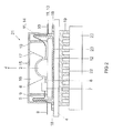
- FIG. 4 shows a lighting device 31 according to a third embodiment, in which now in contrast to the in FIG. 1 and FIG. 2
- the cover 32 is not on the support member 4 (here: a lamp housing or a dedicated heat sink) is attached. Rather, the carrier element 4 and the cover 32 are now jointly on a base support 33, which is designed here as an electrically insulating driver housing for serving as an LED operating device LED driver 34.
- the supply lines 9, 10 lead from the driver 34 to the LED module or the LED chips 2 used here.
- the driver 7 of the LED module can then be dispensed with, or the drivers 7 and 34 work in a division of labor, as shown here , Instead of a driver 7 but can still be present another element, for. B. a sensor element.
- tubular cable bushings 36 For this purpose, the housing 33 on the support side 35 projecting tubular cable bushings 36. These line bushings 36 fit between the support element 4 seated on the support side 35 and the cover 32 resting on the support side 35 and surrounding the support element 4. Alternatively, bushings may be incorporated in the support element 4 and / or in the support surface of the cover 32.
- the cable bushings 36 thus extend into the cavity 6, is formed by the cover 32 and the support member 4.
- the feedthroughs 36 form a labyrinth for the supply lines 9, 10, since there is no linear connection to a live part in the cavity; Rather, the respective supply line 9, 10 must extend laterally to the pipe direction after exiting the duct 36.
- the length of the air and creepage distance is determined in each case firstly by the lateral spacing of the bushings 36 from a live part and secondly by the height of the bushings 36.
- the cover 32 is now stirred in several pieces and comprises at least one support edge 37, on the light emitting side, a lid 38 is placed.
- the lid 38 has at least the transparent area 15 analog to FIG. 1 and FIG. 2 on, as well as the substrate 22 of the LED module on the insulation 23 pressing projections 24 or pins.
- the projections 24 press the substrate 22 on the insulating layer 23 and on the support member 4.
- the support member 4 can on the support side 35th the driver housing 33 are attached with all suitable types of attachment, for. B. glued, screwed, pressed, etc.
- the LED module is firmly pressed by simple means.
- FIG. 5 shows a lighting device 39 according to a fourth embodiment with a similar structure as the lighting device 31 from FIG. 4 which now but now to receive a plurality of separately manufactured LED or, as shown here, LED modules is set up, which are electrically interconnected, for. B. in series, and are supplied via the common driver 34 with power.
- the cover For receiving a plurality of LED modules, the cover here has a plurality of projections 24 per module position. The LED modules are pressed by the projections 24 onto a common carrier element 4.
Landscapes
- Engineering & Computer Science (AREA)
- General Engineering & Computer Science (AREA)
- Physics & Mathematics (AREA)
- Microelectronics & Electronic Packaging (AREA)
- Optics & Photonics (AREA)
- Non-Portable Lighting Devices Or Systems Thereof (AREA)
- Arrangement Of Elements, Cooling, Sealing, Or The Like Of Lighting Devices (AREA)
- Led Device Packages (AREA)
Applications Claiming Priority (1)
| Application Number | Priority Date | Filing Date | Title |
|---|---|---|---|
| DE102008039364A DE102008039364A1 (de) | 2008-08-22 | 2008-08-22 | Halbleiter-Leuchtvorrichtung |
Publications (2)
| Publication Number | Publication Date |
|---|---|
| EP2157358A2 true EP2157358A2 (fr) | 2010-02-24 |
| EP2157358A3 EP2157358A3 (fr) | 2010-03-24 |
Family
ID=41254650
Family Applications (1)
| Application Number | Title | Priority Date | Filing Date |
|---|---|---|---|
| EP09166343A Withdrawn EP2157358A3 (fr) | 2008-08-22 | 2009-07-24 | Dispositif d'éclairage à semi-conducteur |
Country Status (4)
| Country | Link |
|---|---|
| EP (1) | EP2157358A3 (fr) |
| KR (1) | KR20100023758A (fr) |
| CN (1) | CN101655194A (fr) |
| DE (1) | DE102008039364A1 (fr) |
Cited By (4)
| Publication number | Priority date | Publication date | Assignee | Title |
|---|---|---|---|---|
| DE202010016472U1 (de) | 2009-12-15 | 2011-03-24 | Isensee, Gerrit Ragnar Ulrich Friedrich, Maspalomas | Modul zur Simulation einer belegten Sitzkontaktmatte in Fahrzeugen |
| DE102010038921A1 (de) * | 2010-08-04 | 2012-02-09 | Osram Ag | Optische Vorrichtung und Beleuchtungseinheit mit optischer Vorrichtung |
| EP3217084A1 (fr) * | 2016-03-10 | 2017-09-13 | H4X e.U. | Lampe |
| IT201800003641A1 (it) * | 2018-03-16 | 2019-09-16 | Castaldi Lighting S P A | Proiettore ad elevata compattezza. |
Families Citing this family (12)
| Publication number | Priority date | Publication date | Assignee | Title |
|---|---|---|---|---|
| DE102010029227A1 (de) * | 2010-05-21 | 2011-11-24 | Osram Gesellschaft mit beschränkter Haftung | Leuchtvorrichtung |
| DE102010043295B4 (de) | 2010-11-03 | 2020-10-08 | Lisa Dräxlmaier GmbH | Lichtemittermodul |
| DE102010043296B4 (de) | 2010-11-03 | 2020-10-08 | Lisa Dräxlmaier GmbH | Lichtemittermodul mit Umlenkoptik |
| DE102011005047B3 (de) | 2011-03-03 | 2012-09-06 | Osram Ag | Leuchtvorrichtung |
| CN102679187B (zh) * | 2011-03-07 | 2016-06-01 | 秦彪 | 用于照明的led光模组和led芯片 |
| CN102927484B (zh) * | 2012-11-26 | 2013-11-20 | 殷逢宝 | 一种大功率led灯具 |
| DE202013103294U1 (de) * | 2013-07-23 | 2014-10-27 | Zumtobel Lighting Gmbh | LED-Beleuchtungsmodul |
| DE202014102430U1 (de) | 2014-05-23 | 2015-05-27 | Bernd Mitecki | Leuchtvorrichtung umfassend mindestens eine Halbleiterlichtquelle und Fassadenleuchtvorrichtung mit mindestens eine Halbleiterlichtquelle |
| DE102017105722A1 (de) | 2017-03-16 | 2018-09-20 | Siteco Beleuchtungstechnik Gmbh | LED-Leuchtenmodul mit flächigem Träger für LEDs |
| CN107218543A (zh) * | 2017-07-21 | 2017-09-29 | 厦门乾照照明有限公司 | 一种led投光灯 |
| DE102019100527A1 (de) | 2019-01-10 | 2020-07-16 | Hans-Peter Wilfer | Abdeckelement zur Abdeckung einer in einer planen Geräteoberfläche verbauten LED |
| DE102024121162A1 (de) * | 2024-07-25 | 2025-07-17 | Diehl Aerospace Gmbh | Leuchte für eine Passagierkabine eines Passagierflugzeuges auf Basis eines H-Profils |
Citations (2)
| Publication number | Priority date | Publication date | Assignee | Title |
|---|---|---|---|---|
| DE9103560U1 (de) * | 1991-03-23 | 1991-06-27 | Brökelmann, Jaeger & Busse GmbH & Co, 5760 Arnsberg | Lampenfassung, insbesondere für Halogenlampen |
| DE202007008258U1 (de) | 2007-04-30 | 2007-10-31 | Lumitech Produktion Und Entwicklung Gmbh | LED-Leuchtmittel |
Family Cites Families (14)
| Publication number | Priority date | Publication date | Assignee | Title |
|---|---|---|---|---|
| US20040120140A1 (en) * | 2002-03-27 | 2004-06-24 | Fye Michael E. | Illuminated graphics using fluorescing materials |
| EP1590831A2 (fr) * | 2003-02-05 | 2005-11-02 | Acol Technologies S.A. | Dispositifs photoemetteurs |
| US20050077616A1 (en) * | 2003-10-09 | 2005-04-14 | Ng Kee Yean | High power light emitting diode device |
| DE202004001720U1 (de) * | 2004-02-05 | 2004-04-08 | Lian-Hwau Molding Enterprise Co., Ltd., YungKang | Autoleuchte |
| JP2005347471A (ja) * | 2004-06-02 | 2005-12-15 | Seiko Epson Corp | 光源装置及びプロジェクタ |
| ATE465374T1 (de) * | 2004-11-01 | 2010-05-15 | Panasonic Corp | Lichtemittierendes modul, beleuchtungsvorrichtung und anzeigevorrichtung |
| US7262438B2 (en) * | 2005-03-08 | 2007-08-28 | Avago Technologies Ecbu Ip (Singapore) Pte. Ltd. | LED mounting having increased heat dissipation |
| JP3998027B2 (ja) * | 2005-07-25 | 2007-10-24 | 松下電工株式会社 | Ledを用いた照明器具 |
| US8465175B2 (en) * | 2005-11-29 | 2013-06-18 | GE Lighting Solutions, LLC | LED lighting assemblies with thermal overmolding |
| CN101846247B (zh) * | 2005-12-22 | 2013-04-17 | 松下电器产业株式会社 | 具有led的照明器具 |
| US7708452B2 (en) * | 2006-06-08 | 2010-05-04 | Lighting Science Group Corporation | Lighting apparatus including flexible power supply |
| TWM304736U (en) * | 2006-07-06 | 2007-01-11 | Augux Co Ltd | Illuminating source structure for heat dissipation type LED signal lamp |
| US20080080187A1 (en) * | 2006-09-28 | 2008-04-03 | Purinton Richard S | Sealed LED light bulb |
| DE102006048230B4 (de) * | 2006-10-11 | 2012-11-08 | Osram Ag | Leuchtdiodensystem, Verfahren zur Herstellung eines solchen und Hinterleuchtungseinrichtung |
-
2008
- 2008-08-22 DE DE102008039364A patent/DE102008039364A1/de not_active Withdrawn
-
2009
- 2009-07-24 EP EP09166343A patent/EP2157358A3/fr not_active Withdrawn
- 2009-08-20 KR KR1020090077104A patent/KR20100023758A/ko not_active Withdrawn
- 2009-08-21 CN CN200910168512A patent/CN101655194A/zh active Pending
Patent Citations (2)
| Publication number | Priority date | Publication date | Assignee | Title |
|---|---|---|---|---|
| DE9103560U1 (de) * | 1991-03-23 | 1991-06-27 | Brökelmann, Jaeger & Busse GmbH & Co, 5760 Arnsberg | Lampenfassung, insbesondere für Halogenlampen |
| DE202007008258U1 (de) | 2007-04-30 | 2007-10-31 | Lumitech Produktion Und Entwicklung Gmbh | LED-Leuchtmittel |
Cited By (8)
| Publication number | Priority date | Publication date | Assignee | Title |
|---|---|---|---|---|
| DE202010016472U1 (de) | 2009-12-15 | 2011-03-24 | Isensee, Gerrit Ragnar Ulrich Friedrich, Maspalomas | Modul zur Simulation einer belegten Sitzkontaktmatte in Fahrzeugen |
| DE102010038921A1 (de) * | 2010-08-04 | 2012-02-09 | Osram Ag | Optische Vorrichtung und Beleuchtungseinheit mit optischer Vorrichtung |
| DE102010038921B4 (de) * | 2010-08-04 | 2021-03-25 | Osram Gmbh | Optische Vorrichtung und Beleuchtungseinheit mit optischer Vorrichtung |
| EP3217084A1 (fr) * | 2016-03-10 | 2017-09-13 | H4X e.U. | Lampe |
| AT518330A3 (de) * | 2016-03-10 | 2019-04-15 | H4X Eu | Leuchte |
| US10480770B2 (en) | 2016-03-10 | 2019-11-19 | H4X E.U. | Lamp |
| AT518330B1 (de) * | 2016-03-10 | 2021-03-15 | H4X Eu | Leuchte |
| IT201800003641A1 (it) * | 2018-03-16 | 2019-09-16 | Castaldi Lighting S P A | Proiettore ad elevata compattezza. |
Also Published As
| Publication number | Publication date |
|---|---|
| DE102008039364A1 (de) | 2010-03-04 |
| EP2157358A3 (fr) | 2010-03-24 |
| KR20100023758A (ko) | 2010-03-04 |
| CN101655194A (zh) | 2010-02-24 |
Similar Documents
| Publication | Publication Date | Title |
|---|---|---|
| EP2157358A2 (fr) | Dispositif d'éclairage à semi-conducteur | |
| DE102010043918B4 (de) | Halbleiterlampe | |
| EP2499420B1 (fr) | Dispositif d'éclairage | |
| DE102013216961B4 (de) | Zusammenbau einer Halbleiterlampe aus separat hergestellten Bauteilen | |
| DE102010030702A1 (de) | Halbleiterlampe | |
| EP2198196B1 (fr) | Lampe | |
| EP2507548B1 (fr) | Lamp del pour reequpment | |
| EP2815177B1 (fr) | Module d'éclairage | |
| WO2008017652A1 (fr) | Lampe | |
| EP2783153B1 (fr) | Corps de refroidissement de dispositif d'éclairage à semi-conducteur comprenant des parties en matière plastique | |
| EP2459926A1 (fr) | Dispositif d'éclairage et procédé de fabrication d'un dispositif d'éclairage | |
| DE102010029593B4 (de) | LED-Modul mit Doppeldiffusor | |
| EP2313683B1 (fr) | Dispositif d'éclairage | |
| DE102010003680A1 (de) | Halbleiterlampe | |
| DE102014110087A1 (de) | Licht emittierendes Modul, Beleuchtungsvorrichtung und Beleuchtungsausstattung | |
| DE102014215939A1 (de) | Beleuchtungsvorrichtung und Verfahren zum Herstellen einer solchen | |
| DE102010034664B4 (de) | Lichtquelle | |
| DE202013009386U1 (de) | Halbleiterleuchtvorrichtung | |
| DE102007056270B4 (de) | Beleuchtungseinheit mit einer LED-Lichtquelle | |
| EP2443389A1 (fr) | Corps de refroidissement pour éléments luminescents à semi-conducteur | |
| WO2014063975A1 (fr) | Dispositif d'éclairage pourvu d'un corps de refroidissement et au moins d'une source lumineuse semi-conductrice | |
| DE102018218175A1 (de) | Leuchte und scheinwerfer |
Legal Events
| Date | Code | Title | Description |
|---|---|---|---|
| PUAI | Public reference made under article 153(3) epc to a published international application that has entered the european phase |
Free format text: ORIGINAL CODE: 0009012 |
|
| PUAL | Search report despatched |
Free format text: ORIGINAL CODE: 0009013 |
|
| AK | Designated contracting states |
Kind code of ref document: A2 Designated state(s): AT BE BG CH CY CZ DE DK EE ES FI FR GB GR HR HU IE IS IT LI LT LU LV MC MK MT NL NO PL PT RO SE SI SK SM TR |
|
| AX | Request for extension of the european patent |
Extension state: AL BA RS |
|
| AK | Designated contracting states |
Kind code of ref document: A3 Designated state(s): AT BE BG CH CY CZ DE DK EE ES FI FR GB GR HR HU IE IS IT LI LT LU LV MC MK MT NL NO PL PT RO SE SI SK SM TR |
|
| AX | Request for extension of the european patent |
Extension state: AL BA RS |
|
| 17P | Request for examination filed |
Effective date: 20100621 |
|
| 17Q | First examination report despatched |
Effective date: 20100715 |
|
| RAP1 | Party data changed (applicant data changed or rights of an application transferred) |
Owner name: OSRAM AG |
|
| RAP1 | Party data changed (applicant data changed or rights of an application transferred) |
Owner name: OSRAM GMBH |
|
| RAP1 | Party data changed (applicant data changed or rights of an application transferred) |
Owner name: OSRAM GMBH |
|
| RIC1 | Information provided on ipc code assigned before grant |
Ipc: F21S 8/00 20060101AFI20131213BHEP Ipc: F21Y 101/02 20060101ALN20131213BHEP Ipc: H01L 33/00 20100101ALI20131213BHEP |
|
| GRAP | Despatch of communication of intention to grant a patent |
Free format text: ORIGINAL CODE: EPIDOSNIGR1 |
|
| INTG | Intention to grant announced |
Effective date: 20140312 |
|
| STAA | Information on the status of an ep patent application or granted ep patent |
Free format text: STATUS: THE APPLICATION IS DEEMED TO BE WITHDRAWN |
|
| 18D | Application deemed to be withdrawn |
Effective date: 20140723 |