EP2157396A2 - Porte de véhicule pour véhicules blindés comportant un pêne de protection contre les mines - Google Patents
Porte de véhicule pour véhicules blindés comportant un pêne de protection contre les mines Download PDFInfo
- Publication number
- EP2157396A2 EP2157396A2 EP09166380A EP09166380A EP2157396A2 EP 2157396 A2 EP2157396 A2 EP 2157396A2 EP 09166380 A EP09166380 A EP 09166380A EP 09166380 A EP09166380 A EP 09166380A EP 2157396 A2 EP2157396 A2 EP 2157396A2
- Authority
- EP
- European Patent Office
- Prior art keywords
- vehicle door
- handle
- movement
- door according
- vehicle
- Prior art date
- Legal status (The legal status is an assumption and is not a legal conclusion. Google has not performed a legal analysis and makes no representation as to the accuracy of the status listed.)
- Granted
Links
Images


Classifications
-
- E—FIXED CONSTRUCTIONS
- E05—LOCKS; KEYS; WINDOW OR DOOR FITTINGS; SAFES
- E05B—LOCKS; ACCESSORIES THEREFOR; HANDCUFFS
- E05B83/00—Vehicle locks specially adapted for particular types of wing or vehicle
- E05B83/01—Locks for military or armoured vehicles
-
- E—FIXED CONSTRUCTIONS
- E05—LOCKS; KEYS; WINDOW OR DOOR FITTINGS; SAFES
- E05B—LOCKS; ACCESSORIES THEREFOR; HANDCUFFS
- E05B83/00—Vehicle locks specially adapted for particular types of wing or vehicle
- E05B83/36—Locks for passenger or like doors
-
- F—MECHANICAL ENGINEERING; LIGHTING; HEATING; WEAPONS; BLASTING
- F41—WEAPONS
- F41H—ARMOUR; ARMOURED TURRETS; ARMOURED OR ARMED VEHICLES; MEANS OF ATTACK OR DEFENCE, e.g. CAMOUFLAGE, IN GENERAL
- F41H5/00—Armour; Armour plates
- F41H5/22—Manhole covers, e.g. on tanks; Doors on armoured vehicles or structures
- F41H5/226—Doors on armoured vehicles or structures
-
- F—MECHANICAL ENGINEERING; LIGHTING; HEATING; WEAPONS; BLASTING
- F41—WEAPONS
- F41H—ARMOUR; ARMOURED TURRETS; ARMOURED OR ARMED VEHICLES; MEANS OF ATTACK OR DEFENCE, e.g. CAMOUFLAGE, IN GENERAL
- F41H7/00—Armoured or armed vehicles
- F41H7/02—Land vehicles with enclosing armour, e.g. tanks
- F41H7/04—Armour construction
Definitions
- the invention relates to a vehicle door for armored vehicles, which has a movable in a locking position anti-mine bar and a door lock, which is unlocked for opening the vehicle door by means of a handle.
- Vehicle doors typically have a door lock to hold the vehicle door in the closed position.
- the door lock can be designed in the manner of a rotary latch for receiving a locking bolt.
- mine protection bars are in this case usually designed rod-shaped or rod-shaped and engage in the locking position mostly in corresponding arranged on the vehicle frame holding elements.
- the vehicle door may also include a vehicle door brake braking device used to secure the door, which may have a heavy weight in armored vehicles, against unwanted movement, for example in the case where the vehicle is transverse to a slope.
- the braking device can be released by means of the handle, which at the same time unlocks the door lock to open the vehicle door.
- the handle for a vehicle door movement must be actuated permanently, so that letting go of the handle leads to a braking of the vehicle door movement.
- known vehicle doors have an additional handle, by which the mine protection latch is movable into the locking position and back.
- a disadvantage of such a configuration is that for opening or closing the door several handles must be used, whereby the opening and closing operation is delayed in time.
- a braking device that must be operated to move the vehicle door, also occurs in a special way the disadvantage that a person in the vehicle, although the first handle to release the braking device when closing the door, but then it There is a risk that the person inadvertently removes the handle for locking the anti-mine bar not activated, so that full protection against mines or other threats is not given.
- the invention has the object to design a vehicle door of the type mentioned, which can be opened in a simple manner.
- a basic idea of the invention lies in the fact that by means of the handle, which unlocks the door lock to open the vehicle door, the anti-mine bar can also be moved into the locking position.
- the vehicle door for the basic functions of opening the door lock and locking the anti-mine bar or unlocking the anti-mine bar only has a handle that must be operated so that the door can be opened in a simple manner.
- the door lock, which is provided in addition to the anti-mine bar can be designed in the manner of a rotary latch and in particular receive a locking bolt.
- the handle is rotatably mounted, wherein a rotational movement in the one direction of rotation unlocks the door lock and a rotational movement in the other direction of rotation moves the mine protection latch in the locked position.
- the vehicle door can thus be configured such that when the mine protection bolt is locked, a first rotary movement of the handle leads to unlocking the anti-mine bar, with a rotational movement immediately following it in the same direction of rotation for unlocking the door lock, so that the vehicle door with a continuous movement of the Handle can be opened in one direction.
- Baskülver gleich can be interposed between the handle and the mine protection.
- the handle is arranged on the inside of the vehicle door.
- an external handle by means of which the door lock can be unlocked, said external handle can be decoupled from the mine protection bar, so that from the outside by means of the outer handle, although the door lock is unlocked, but not the anti-mine bar can be moved from the locked position to the unlocked position.
- a protection of the vehicle crew against intruders is given when the mine protection bar is in the locked position.
- the vehicle door can also advantageously have a braking device which brakes the vehicle door movement and which can also be released by means of the handle.
- the braking device may in this case comprise a gas spring which can be ventilated for release via a release element by means of the handle. So that the vehicle door can also be moved from the outside, in a preferred embodiment of the vehicle door the braking device can also be detachable by means of the outer handle.
- the braking effect of the braking device is taken to the vehicle door movement in the last movement portion of a movement of the vehicle door in the closed position.
- the last movement section may extend from the closed position over a predetermined angular range of 0 ° to 45 °, in particular from 0 ° to 30 °.
- the braking device can have a brake release device, which in the last movement section of the movement of the vehicle door into the closed position, the braking effect of the braking device reduced and in particular automatically releases.
- the brake release device may in this case comprise a switching element, in particular a cam, which is moved in the vehicle door movement and which acts in the last movement section on the release element for releasing the brake device.
- the brake release device may further comprise a telescopic linkage, which is connected for the articulation of the switching element at one end portion with the switching element, and which is connectable at the other end portion with the vehicle, in particular via a pivot bearing.
- a telescopic linkage which is connected for the articulation of the switching element at one end portion with the switching element, and which is connectable at the other end portion with the vehicle, in particular via a pivot bearing.
- the switching element may in this case have a switching cam, which is arranged on the switching element such that it acts on the release element only in the last movement section.
- the switching element may also be mounted eccentrically and in turn be configured such that only in the last movement section, an effect on the release element.
- the actuator may further be configured such that the handle for manually releasing the brake device is to be actuated permanently.
- the vehicle door movement is unbraked in the last movement section.
- the last movement section thus runs in an empty angle.
- the vehicle door can be closed by its own momentum or pushed or pulled in a simple manner.
- the vehicle door has two or more mine protection bars, which are movable by means of the handle into the locking position.
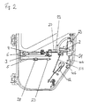
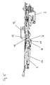
- FIGS. 1 . 2 and 4 show an interior view of a vehicle door for an unillustrated armored vehicle with the inner lining removed.
- the vehicle door 1 has an armored glass pane 10 and is connected via the hinges 11 to the vehicle.
- the vehicle door 1 has an internal handle 2, by means of which the door lock 42, which includes a pre-locking and a main detent function and receives a correspondingly formed locking pin, can be opened.
- the armored vehicle door has two anti-mine bar 40a and 40b, which are movable into a locking position, not shown, in which they engage the arranged on the vehicle frame holding members 41 a and 41 b to succumb to an increased level of protection.
- the handle 2 is in all representations in a zero position. Starting from this zero position, the handle 2 with the vehicle door closed 1 are brought by a rotational movement in a clockwise direction in a locking position in which the anti-mine bar 40a, 40b engage in the holding elements 41 a, 41 b.
- the handle mechanism 29 is configured such that the rotational movement of the handle 2 is deflected into corresponding linear extension movements of the mine protection bars 40a, 40b.
- the handle mechanism 29 is thus designed in the manner of a Baskülver gleiches.
- the handle 2 can be brought back to the zero position by a counterclockwise rotary movement, so that the anti-mine bars 40a, 40b are unlocked.
- the handle 2 To open the vehicle door, however, the handle 2 must be moved even further counterclockwise, so that the door lock 42 is unlocked.
- a driving element 50 is rotatably disposed on the handle 2, which acts on an intermediate element 21 so that upon rotation of the handle 2 counterclockwise starting from the zero position, the rotatably mounted and guided via a slot guide intermediate member 21 is taken and rotated , The rotational movement of the intermediate element is transmitted via the linkage 51 to the rotatably mounted rotary member 52, which is in communication with the door lock 42 for unlocking.
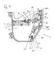
- the armored vehicle door As in Fig. 3 shown, an outer handle 12 which is disposed over a spring 55 by the spring-loaded lock cylinder 34.
- the outer handle 12 By means of the outer handle 12 can as in Fig. 4 also shown the door lock 42 are opened.
- a rotary member 53 is rotatably disposed on the inside of the vehicle door 1. During a rotational movement of the outer handle 12, the rotary member 53 is rotated in the same way, so that the door lock 42 can be unlocked via the linkage 56 and the rotary piece 52.
- the door lock 42 can be unlocked via the outer handle 12, there is no possibility to move the anti-mine bars 40a, 40b over the outer handle 12 into the locking position. This also contributes to the slot 57 in the rotary member 53, so that a rotational movement of the outer handle 12 is not transmitted clockwise to the linkage 56 and thus a mechanical decoupling is given.
- the emergency release 36 ( Fig. 3 ) Acted directly on the handle mechanism 29 by means of a suitably designed key and thereby an emergency release of the mine protection bars 40 a, 40 b are achieved
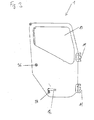
- the vehicle door 1 can be opened after unlocking by a predetermined angle until a damping element 27, which is arranged on a stop device 5, abuts against a door stop 28.
- the vehicle door 1 on a brake device comprising a gas spring 3.
- the gas spring 3 is connected at one end to a vehicle-fixed rod 6 via a rotary bearing 35 to the vehicle.
- a door movement is braked in the unventilated state of the gas spring 3.
- the braking device is designed such that it can be released manually.
- it has an actuating device which comprises the handle 2 and the outer handle 12.
- the handles 2 and 12 are mechanically connected to the intermediate element 21 as already described, which rotatably follows a rotational movement of the handles 2 and 12.
- the intermediate element 21 has an actuating surface which comes into contact with a predetermined angle of pivoting of the intermediate element 21 with a lever 22 which is arranged on the vehicle door 1 via the pivot bearing 25.
- a push rod 23 is moved, which abuts against a stop element 24 of an actuating element 16.
- the actuating element 16 is rotatably mounted on the vehicle door 1 via a pivot bearing 17.
- the actuating element 16 in this case has an actuating switch 9, which abuts upon rotation of the actuating element 16 against a pin-shaped release element 8, which aerates the gas spring 3.
- the braking effect is reduced to the door movement, so that the vehicle door 1 can be moved by the operation of the handle 2 and the outer handle 12.
- both the door lock 42 can be unlocked by means of the handle 2 and the mine protection bars 40a, 40b are moved into the locking position and the braking device 3 are released, so that opening, closing and locking the door in a single and easy way possible is.
- the vehicle door 1 also has a brake release device, which reduces the braking effect of the brake device on the vehicle door movement in the last movement section of a movement of the vehicle door 1 in the closed position.
- the brake release device in this case comprises a telescopic linkage 4, which is connected at one end portion to the vehicle via the vehicle-fixed rod 6 by means of a pivot bearing 32.
- a cam is hinged as a switching element 7.
- the switching element 7 is connected via a pivot bearing 14 with the vehicle door 1.
- the pivot bearing 14 is in this case arranged eccentrically to the switching element 7.
- the switching element 7 has a switching cam 31, which at a rotation of the switching element 7 by a predetermined angular amount of a driving piece 18, which is arranged on an arm 19 of the actuating element 16, entrains and thus causes a rotational movement of the actuating element 16.
- the actuating element 16 can in turn act on the pin-shaped release element 8 and reduce the braking effect.
- the switching element 7 is configured and arranged such that the switching cam 31 only acts on the driving piece 18 when the door is in the last movement portion of a movement of the vehicle door 1 in the closed position.
- This last movement section extends from the closed position over an angular range of 0 ° to 30 °.
- the brake device is thus released automatically via the brake release device in the last movement section.
- the brake release device In the angular range of 0 ° to 30 ° there is no braking effect of the gas spring 3 on the vehicle door movement.
Landscapes
- Engineering & Computer Science (AREA)
- General Engineering & Computer Science (AREA)
- Lock And Its Accessories (AREA)
Applications Claiming Priority (1)
| Application Number | Priority Date | Filing Date | Title |
|---|---|---|---|
| DE200810039509 DE102008039509B4 (de) | 2008-08-23 | 2008-08-23 | Fahrzeugtür für gepanzerte Fahrzeuge mit einem Minenschutzriegel |
Publications (3)
| Publication Number | Publication Date |
|---|---|
| EP2157396A2 true EP2157396A2 (fr) | 2010-02-24 |
| EP2157396A3 EP2157396A3 (fr) | 2013-04-03 |
| EP2157396B1 EP2157396B1 (fr) | 2014-02-26 |
Family
ID=41415154
Family Applications (1)
| Application Number | Title | Priority Date | Filing Date |
|---|---|---|---|
| EP20090166380 Active EP2157396B1 (fr) | 2008-08-23 | 2009-07-24 | Porte de véhicule pour véhicules blindés comportant un pêne de protection contre les mines |
Country Status (2)
| Country | Link |
|---|---|
| EP (1) | EP2157396B1 (fr) |
| DE (1) | DE102008039509B4 (fr) |
Cited By (3)
| Publication number | Priority date | Publication date | Assignee | Title |
|---|---|---|---|---|
| EP2362041A1 (fr) * | 2010-02-19 | 2011-08-31 | Krauss-Maffei Wegmann GmbH & Co. KG | Verrouillage de protection contre les mines pour l'agencement sur des portes de véhicules militaires |
| WO2012000605A1 (fr) * | 2010-06-11 | 2012-01-05 | Rheinmetall Radfahrzeuge Gmbh | Porte de véhicule pour véhicules blindés |
| CN110374424A (zh) * | 2019-08-12 | 2019-10-25 | 中国重汽集团济南动力有限公司 | 一种新型的防雷锁装置 |
Families Citing this family (6)
| Publication number | Priority date | Publication date | Assignee | Title |
|---|---|---|---|---|
| GB2462116B (en) | 2008-07-25 | 2012-03-21 | Gm Global Tech Operations Inc | Vehicle side door assembly |
| US8360486B2 (en) | 2008-11-05 | 2013-01-29 | GM Global Technology Operations LLC | Vehicle side door assembly |
| DE102010036607A1 (de) | 2010-07-24 | 2012-01-26 | Krauss-Maffei Wegmann Gmbh & Co. Kg | Minenschutzverriegelung und Verfahren zur Entriegelung einer Minenschutzverriegelung |
| DE102011056721A1 (de) | 2011-12-20 | 2013-06-20 | Krauss-Maffei Wegmann Gmbh & Co. Kg | Fahrzeugtür für gepanzerte Fahrzeuge |
| CN111119582B (zh) * | 2019-12-31 | 2024-08-30 | 佛山佐尔汽车部件有限公司 | 一种三点式机舱门锁机构 |
| TR202007996A2 (tr) * | 2020-05-22 | 2020-06-22 | Secant Teknoloji Gelistirme Sanayi Ve Ticaret Anonim Sirketi | Zırhlı araçlar için bir kilit mekanizması |
Family Cites Families (7)
| Publication number | Priority date | Publication date | Assignee | Title |
|---|---|---|---|---|
| DE7014950U (de) * | 1900-01-01 | F Driescher Elektrobedarf | Betätigungsgriff für Türvercschlüsse | |
| DE821057C (de) * | 1948-11-03 | 1951-11-15 | Siemens & Halske A G | Baskuelverschluss fuer druckwasserdichte Behaelter, insbesondere fuer Gehaeuse elektrischer Apparate |
| DE1685712U (de) * | 1953-12-24 | 1954-10-28 | Tack & Gabel | Fuer kraftfahrzeugtueren bestimmter baskuelverschluss. |
| DE1959597U (de) * | 1967-01-07 | 1967-05-03 | C W Kehrs & Co G M B H | Kunststoffschrank, insbesondere kabelverteilerschrank. |
| DE2949680C2 (de) * | 1979-12-11 | 1986-04-03 | Dr.Ing.H.C. F. Porsche Ag, 7000 Stuttgart | Vorrichtung zum Öffnen und Schließen eines Einstiegs für ein Panzerfahrzeug mittels eines Lukendeckels |
| US4641865A (en) * | 1982-09-02 | 1987-02-10 | The Eastern Company | Closure control mechanism |
| WO2000030931A1 (fr) * | 1998-11-26 | 2000-06-02 | Talleres Guerra, S.L. | Dispositif de fermeture etanche, instantanee et centralisee |
-
2008
- 2008-08-23 DE DE200810039509 patent/DE102008039509B4/de not_active Expired - Fee Related
-
2009
- 2009-07-24 EP EP20090166380 patent/EP2157396B1/fr active Active
Cited By (3)
| Publication number | Priority date | Publication date | Assignee | Title |
|---|---|---|---|---|
| EP2362041A1 (fr) * | 2010-02-19 | 2011-08-31 | Krauss-Maffei Wegmann GmbH & Co. KG | Verrouillage de protection contre les mines pour l'agencement sur des portes de véhicules militaires |
| WO2012000605A1 (fr) * | 2010-06-11 | 2012-01-05 | Rheinmetall Radfahrzeuge Gmbh | Porte de véhicule pour véhicules blindés |
| CN110374424A (zh) * | 2019-08-12 | 2019-10-25 | 中国重汽集团济南动力有限公司 | 一种新型的防雷锁装置 |
Also Published As
| Publication number | Publication date |
|---|---|
| EP2157396A3 (fr) | 2013-04-03 |
| EP2157396B1 (fr) | 2014-02-26 |
| DE102008039509A1 (de) | 2010-03-04 |
| DE102008039509B4 (de) | 2014-01-23 |
Similar Documents
| Publication | Publication Date | Title |
|---|---|---|
| EP2157396B1 (fr) | Porte de véhicule pour véhicules blindés comportant un pêne de protection contre les mines | |
| EP2094923B1 (fr) | Dispositif de verrouillage pour portes coulissantes d'aéronefs, en particulier d'hélicoptères | |
| DE102015122365A1 (de) | Türgriffanordnung für ein Kraftfahrzeug | |
| DE29507642U1 (de) | Kraftfahrzeugtürverschluß | |
| DE202010000528U1 (de) | Verriegelungsmechanismus für ein Gehäuse und dafür geeignetes Schloss | |
| DE102009029031A1 (de) | Gesperre | |
| DE102014114945A1 (de) | Kraftfahrzeugtürschloss | |
| DE102013216320A1 (de) | Türgriffeinheit mit Sicherheitsfunktion | |
| DE10320447A1 (de) | Kraftfahrzeugtürverschluss | |
| DE102011115009A1 (de) | Betätigungsvorrichtung für ein Türschloss | |
| EP3179021B1 (fr) | Système de poignée de porte de véhicule | |
| DE10114438A1 (de) | Schließeinrichtung mit Zuziehhilfe | |
| DE102010041913A1 (de) | Entriegelungsvorrichtung | |
| DE19519010C2 (de) | Kraftfahrzeugtürverschluß | |
| DE102008016319B4 (de) | Schloss mit einer Sicherheitseinrichtung | |
| DE202018103048U1 (de) | Schloss | |
| DE4339654A1 (de) | Kraftfahrzeugtürverschluß | |
| DE102010036607A1 (de) | Minenschutzverriegelung und Verfahren zur Entriegelung einer Minenschutzverriegelung | |
| EP2157394B1 (fr) | Porte pour véhicule blindé | |
| DE102016108417A1 (de) | Kraftfahrzeugtürschloss | |
| DE10343622B4 (de) | Schloss mit einer Drehfalle und Sperrklinke | |
| EP1344882A2 (fr) | Fermeture pour chambres froides | |
| DE102016207938A1 (de) | Schloss für einen schwenkbaren Flügel | |
| EP3118401A1 (fr) | Verrour pour le chant d'un battant | |
| EP4244452B1 (fr) | Verrou d'écartement de porte |
Legal Events
| Date | Code | Title | Description |
|---|---|---|---|
| PUAI | Public reference made under article 153(3) epc to a published international application that has entered the european phase |
Free format text: ORIGINAL CODE: 0009012 |
|
| AK | Designated contracting states |
Kind code of ref document: A2 Designated state(s): AT BE BG CH CY CZ DE DK EE ES FI FR GB GR HR HU IE IS IT LI LT LU LV MC MK MT NL NO PL PT RO SE SI SK SM TR |
|
| AX | Request for extension of the european patent |
Extension state: AL BA RS |
|
| PUAL | Search report despatched |
Free format text: ORIGINAL CODE: 0009013 |
|
| AK | Designated contracting states |
Kind code of ref document: A3 Designated state(s): AT BE BG CH CY CZ DE DK EE ES FI FR GB GR HR HU IE IS IT LI LT LU LV MC MK MT NL NO PL PT RO SE SI SK SM TR |
|
| AX | Request for extension of the european patent |
Extension state: AL BA RS |
|
| RIC1 | Information provided on ipc code assigned before grant |
Ipc: F41H 7/04 20060101AFI20130225BHEP Ipc: F41H 5/22 20060101ALI20130225BHEP Ipc: B60J 5/00 20060101ALI20130225BHEP Ipc: E05B 65/12 20060101ALI20130225BHEP |
|
| 17P | Request for examination filed |
Effective date: 20130322 |
|
| GRAP | Despatch of communication of intention to grant a patent |
Free format text: ORIGINAL CODE: EPIDOSNIGR1 |
|
| INTG | Intention to grant announced |
Effective date: 20131009 |
|
| GRAS | Grant fee paid |
Free format text: ORIGINAL CODE: EPIDOSNIGR3 |
|
| GRAA | (expected) grant |
Free format text: ORIGINAL CODE: 0009210 |
|
| AK | Designated contracting states |
Kind code of ref document: B1 Designated state(s): AT BE BG CH CY CZ DE DK EE ES FI FR GB GR HR HU IE IS IT LI LT LU LV MC MK MT NL NO PL PT RO SE SI SK SM TR |
|
| REG | Reference to a national code |
Ref country code: GB Ref legal event code: FG4D Free format text: NOT ENGLISH |
|
| RIC1 | Information provided on ipc code assigned before grant |
Ipc: B60J 5/00 20060101ALI20140121BHEP Ipc: F41H 7/04 20060101AFI20140121BHEP Ipc: F41H 5/22 20060101ALI20140121BHEP Ipc: E05B 83/36 20140101ALI20140121BHEP |
|
| REG | Reference to a national code |
Ref country code: CH Ref legal event code: EP |
|
| REG | Reference to a national code |
Ref country code: AT Ref legal event code: REF Ref document number: 653851 Country of ref document: AT Kind code of ref document: T Effective date: 20140315 |
|
| REG | Reference to a national code |
Ref country code: DE Ref legal event code: R096 Ref document number: 502009008839 Country of ref document: DE Effective date: 20140403 |
|
| REG | Reference to a national code |
Ref country code: IE Ref legal event code: FG4D Free format text: LANGUAGE OF EP DOCUMENT: GERMAN |
|
| REG | Reference to a national code |
Ref country code: NL Ref legal event code: VDEP Effective date: 20140226 |
|
| REG | Reference to a national code |
Ref country code: LT Ref legal event code: MG4D |
|
| PG25 | Lapsed in a contracting state [announced via postgrant information from national office to epo] |
Ref country code: LT Free format text: LAPSE BECAUSE OF FAILURE TO SUBMIT A TRANSLATION OF THE DESCRIPTION OR TO PAY THE FEE WITHIN THE PRESCRIBED TIME-LIMIT Effective date: 20140226 Ref country code: IS Free format text: LAPSE BECAUSE OF FAILURE TO SUBMIT A TRANSLATION OF THE DESCRIPTION OR TO PAY THE FEE WITHIN THE PRESCRIBED TIME-LIMIT Effective date: 20140626 Ref country code: NO Free format text: LAPSE BECAUSE OF FAILURE TO SUBMIT A TRANSLATION OF THE DESCRIPTION OR TO PAY THE FEE WITHIN THE PRESCRIBED TIME-LIMIT Effective date: 20140526 |
|
| PG25 | Lapsed in a contracting state [announced via postgrant information from national office to epo] |
Ref country code: FI Free format text: LAPSE BECAUSE OF FAILURE TO SUBMIT A TRANSLATION OF THE DESCRIPTION OR TO PAY THE FEE WITHIN THE PRESCRIBED TIME-LIMIT Effective date: 20140226 Ref country code: CY Free format text: LAPSE BECAUSE OF FAILURE TO SUBMIT A TRANSLATION OF THE DESCRIPTION OR TO PAY THE FEE WITHIN THE PRESCRIBED TIME-LIMIT Effective date: 20140226 Ref country code: SE Free format text: LAPSE BECAUSE OF FAILURE TO SUBMIT A TRANSLATION OF THE DESCRIPTION OR TO PAY THE FEE WITHIN THE PRESCRIBED TIME-LIMIT Effective date: 20140226 Ref country code: NL Free format text: LAPSE BECAUSE OF FAILURE TO SUBMIT A TRANSLATION OF THE DESCRIPTION OR TO PAY THE FEE WITHIN THE PRESCRIBED TIME-LIMIT Effective date: 20140226 Ref country code: PT Free format text: LAPSE BECAUSE OF FAILURE TO SUBMIT A TRANSLATION OF THE DESCRIPTION OR TO PAY THE FEE WITHIN THE PRESCRIBED TIME-LIMIT Effective date: 20140626 |
|
| PG25 | Lapsed in a contracting state [announced via postgrant information from national office to epo] |
Ref country code: HR Free format text: LAPSE BECAUSE OF FAILURE TO SUBMIT A TRANSLATION OF THE DESCRIPTION OR TO PAY THE FEE WITHIN THE PRESCRIBED TIME-LIMIT Effective date: 20140226 Ref country code: LV Free format text: LAPSE BECAUSE OF FAILURE TO SUBMIT A TRANSLATION OF THE DESCRIPTION OR TO PAY THE FEE WITHIN THE PRESCRIBED TIME-LIMIT Effective date: 20140226 |
|
| PG25 | Lapsed in a contracting state [announced via postgrant information from national office to epo] |
Ref country code: DK Free format text: LAPSE BECAUSE OF FAILURE TO SUBMIT A TRANSLATION OF THE DESCRIPTION OR TO PAY THE FEE WITHIN THE PRESCRIBED TIME-LIMIT Effective date: 20140226 Ref country code: RO Free format text: LAPSE BECAUSE OF FAILURE TO SUBMIT A TRANSLATION OF THE DESCRIPTION OR TO PAY THE FEE WITHIN THE PRESCRIBED TIME-LIMIT Effective date: 20140226 Ref country code: EE Free format text: LAPSE BECAUSE OF FAILURE TO SUBMIT A TRANSLATION OF THE DESCRIPTION OR TO PAY THE FEE WITHIN THE PRESCRIBED TIME-LIMIT Effective date: 20140226 Ref country code: CZ Free format text: LAPSE BECAUSE OF FAILURE TO SUBMIT A TRANSLATION OF THE DESCRIPTION OR TO PAY THE FEE WITHIN THE PRESCRIBED TIME-LIMIT Effective date: 20140226 |
|
| REG | Reference to a national code |
Ref country code: DE Ref legal event code: R097 Ref document number: 502009008839 Country of ref document: DE |
|
| PG25 | Lapsed in a contracting state [announced via postgrant information from national office to epo] |
Ref country code: ES Free format text: LAPSE BECAUSE OF FAILURE TO SUBMIT A TRANSLATION OF THE DESCRIPTION OR TO PAY THE FEE WITHIN THE PRESCRIBED TIME-LIMIT Effective date: 20140226 Ref country code: PL Free format text: LAPSE BECAUSE OF FAILURE TO SUBMIT A TRANSLATION OF THE DESCRIPTION OR TO PAY THE FEE WITHIN THE PRESCRIBED TIME-LIMIT Effective date: 20140226 Ref country code: SK Free format text: LAPSE BECAUSE OF FAILURE TO SUBMIT A TRANSLATION OF THE DESCRIPTION OR TO PAY THE FEE WITHIN THE PRESCRIBED TIME-LIMIT Effective date: 20140226 |
|
| PLBE | No opposition filed within time limit |
Free format text: ORIGINAL CODE: 0009261 |
|
| STAA | Information on the status of an ep patent application or granted ep patent |
Free format text: STATUS: NO OPPOSITION FILED WITHIN TIME LIMIT |
|
| 26N | No opposition filed |
Effective date: 20141127 |
|
| PG25 | Lapsed in a contracting state [announced via postgrant information from national office to epo] |
Ref country code: LU Free format text: LAPSE BECAUSE OF FAILURE TO SUBMIT A TRANSLATION OF THE DESCRIPTION OR TO PAY THE FEE WITHIN THE PRESCRIBED TIME-LIMIT Effective date: 20140724 |
|
| REG | Reference to a national code |
Ref country code: DE Ref legal event code: R097 Ref document number: 502009008839 Country of ref document: DE Effective date: 20141127 |
|
| REG | Reference to a national code |
Ref country code: IE Ref legal event code: MM4A |
|
| PG25 | Lapsed in a contracting state [announced via postgrant information from national office to epo] |
Ref country code: SI Free format text: LAPSE BECAUSE OF FAILURE TO SUBMIT A TRANSLATION OF THE DESCRIPTION OR TO PAY THE FEE WITHIN THE PRESCRIBED TIME-LIMIT Effective date: 20140226 |
|
| PG25 | Lapsed in a contracting state [announced via postgrant information from national office to epo] |
Ref country code: IE Free format text: LAPSE BECAUSE OF NON-PAYMENT OF DUE FEES Effective date: 20140724 |
|
| PG25 | Lapsed in a contracting state [announced via postgrant information from national office to epo] |
Ref country code: SM Free format text: LAPSE BECAUSE OF FAILURE TO SUBMIT A TRANSLATION OF THE DESCRIPTION OR TO PAY THE FEE WITHIN THE PRESCRIBED TIME-LIMIT Effective date: 20140226 |
|
| PG25 | Lapsed in a contracting state [announced via postgrant information from national office to epo] |
Ref country code: MT Free format text: LAPSE BECAUSE OF FAILURE TO SUBMIT A TRANSLATION OF THE DESCRIPTION OR TO PAY THE FEE WITHIN THE PRESCRIBED TIME-LIMIT Effective date: 20140226 Ref country code: MC Free format text: LAPSE BECAUSE OF NON-PAYMENT OF DUE FEES Effective date: 20140226 Ref country code: BG Free format text: LAPSE BECAUSE OF FAILURE TO SUBMIT A TRANSLATION OF THE DESCRIPTION OR TO PAY THE FEE WITHIN THE PRESCRIBED TIME-LIMIT Effective date: 20140226 Ref country code: GR Free format text: LAPSE BECAUSE OF FAILURE TO SUBMIT A TRANSLATION OF THE DESCRIPTION OR TO PAY THE FEE WITHIN THE PRESCRIBED TIME-LIMIT Effective date: 20140527 |
|
| REG | Reference to a national code |
Ref country code: FR Ref legal event code: PLFP Year of fee payment: 8 |
|
| PG25 | Lapsed in a contracting state [announced via postgrant information from national office to epo] |
Ref country code: BE Free format text: LAPSE BECAUSE OF FAILURE TO SUBMIT A TRANSLATION OF THE DESCRIPTION OR TO PAY THE FEE WITHIN THE PRESCRIBED TIME-LIMIT Effective date: 20140731 Ref country code: HU Free format text: LAPSE BECAUSE OF FAILURE TO SUBMIT A TRANSLATION OF THE DESCRIPTION OR TO PAY THE FEE WITHIN THE PRESCRIBED TIME-LIMIT; INVALID AB INITIO Effective date: 20090724 Ref country code: TR Free format text: LAPSE BECAUSE OF FAILURE TO SUBMIT A TRANSLATION OF THE DESCRIPTION OR TO PAY THE FEE WITHIN THE PRESCRIBED TIME-LIMIT Effective date: 20140226 |
|
| REG | Reference to a national code |
Ref country code: FR Ref legal event code: PLFP Year of fee payment: 9 |
|
| PG25 | Lapsed in a contracting state [announced via postgrant information from national office to epo] |
Ref country code: MK Free format text: LAPSE BECAUSE OF FAILURE TO SUBMIT A TRANSLATION OF THE DESCRIPTION OR TO PAY THE FEE WITHIN THE PRESCRIBED TIME-LIMIT Effective date: 20140226 |
|
| REG | Reference to a national code |
Ref country code: FR Ref legal event code: PLFP Year of fee payment: 10 |
|
| P01 | Opt-out of the competence of the unified patent court (upc) registered |
Effective date: 20230517 |
|
| REG | Reference to a national code |
Ref country code: DE Ref legal event code: R081 Ref document number: 502009008839 Country of ref document: DE Owner name: KNDS DEUTSCHLAND GMBH & CO. KG, DE Free format text: FORMER OWNER: KRAUSS-MAFFEI WEGMANN GMBH & CO. KG, 80997 MUENCHEN, DE |
|
| REG | Reference to a national code |
Ref country code: AT Ref legal event code: HC Ref document number: 653851 Country of ref document: AT Kind code of ref document: T Owner name: KNDS DEUTSCHLAND GMBH & CO. KG, DE Effective date: 20250203 |
|
| PGFP | Annual fee paid to national office [announced via postgrant information from national office to epo] |
Ref country code: DE Payment date: 20250731 Year of fee payment: 17 |
|
| PGFP | Annual fee paid to national office [announced via postgrant information from national office to epo] |
Ref country code: IT Payment date: 20250731 Year of fee payment: 17 |
|
| PGFP | Annual fee paid to national office [announced via postgrant information from national office to epo] |
Ref country code: GB Payment date: 20250724 Year of fee payment: 17 |
|
| PGFP | Annual fee paid to national office [announced via postgrant information from national office to epo] |
Ref country code: FR Payment date: 20250723 Year of fee payment: 17 Ref country code: AT Payment date: 20250721 Year of fee payment: 17 |
|
| PGFP | Annual fee paid to national office [announced via postgrant information from national office to epo] |
Ref country code: CH Payment date: 20250801 Year of fee payment: 17 |