EP2157498B1 - Informationsverarbeitungsvorrichtung mit zeiger-steuerung - Google Patents
Informationsverarbeitungsvorrichtung mit zeiger-steuerung Download PDFInfo
- Publication number
- EP2157498B1 EP2157498B1 EP08777109.3A EP08777109A EP2157498B1 EP 2157498 B1 EP2157498 B1 EP 2157498B1 EP 08777109 A EP08777109 A EP 08777109A EP 2157498 B1 EP2157498 B1 EP 2157498B1
- Authority
- EP
- European Patent Office
- Prior art keywords
- pointer
- movement
- target object
- input
- information
- Prior art date
- Legal status (The legal status is an assumption and is not a legal conclusion. Google has not performed a legal analysis and makes no representation as to the accuracy of the status listed.)
- Not-in-force
Links
Images











Classifications
-
- G—PHYSICS
- G06—COMPUTING OR CALCULATING; COUNTING
- G06F—ELECTRIC DIGITAL DATA PROCESSING
- G06F3/00—Input arrangements for transferring data to be processed into a form capable of being handled by the computer; Output arrangements for transferring data from processing unit to output unit, e.g. interface arrangements
- G06F3/01—Input arrangements or combined input and output arrangements for interaction between user and computer
- G06F3/03—Arrangements for converting the position or the displacement of a member into a coded form
- G06F3/033—Pointing devices displaced or positioned by the user, e.g. mice, trackballs, pens or joysticks; Accessories therefor
- G06F3/0346—Pointing devices displaced or positioned by the user, e.g. mice, trackballs, pens or joysticks; Accessories therefor with detection of the device orientation or free movement in a three-dimensional [3D] space, e.g. 3D mice, 6-DOF [six degrees of freedom] pointers using gyroscopes, accelerometers or tilt-sensors
-
- G—PHYSICS
- G06—COMPUTING OR CALCULATING; COUNTING
- G06F—ELECTRIC DIGITAL DATA PROCESSING
- G06F3/00—Input arrangements for transferring data to be processed into a form capable of being handled by the computer; Output arrangements for transferring data from processing unit to output unit, e.g. interface arrangements
- G06F3/01—Input arrangements or combined input and output arrangements for interaction between user and computer
- G06F3/017—Gesture based interaction, e.g. based on a set of recognized hand gestures
-
- G—PHYSICS
- G06—COMPUTING OR CALCULATING; COUNTING
- G06F—ELECTRIC DIGITAL DATA PROCESSING
- G06F3/00—Input arrangements for transferring data to be processed into a form capable of being handled by the computer; Output arrangements for transferring data from processing unit to output unit, e.g. interface arrangements
- G06F3/01—Input arrangements or combined input and output arrangements for interaction between user and computer
- G06F3/03—Arrangements for converting the position or the displacement of a member into a coded form
- G06F3/033—Pointing devices displaced or positioned by the user, e.g. mice, trackballs, pens or joysticks; Accessories therefor
- G06F3/0338—Pointing devices displaced or positioned by the user, e.g. mice, trackballs, pens or joysticks; Accessories therefor with detection of limited linear or angular displacement of an operating part of the device from a neutral position, e.g. isotonic or isometric joysticks
-
- G—PHYSICS
- G06—COMPUTING OR CALCULATING; COUNTING
- G06F—ELECTRIC DIGITAL DATA PROCESSING
- G06F3/00—Input arrangements for transferring data to be processed into a form capable of being handled by the computer; Output arrangements for transferring data from processing unit to output unit, e.g. interface arrangements
- G06F3/01—Input arrangements or combined input and output arrangements for interaction between user and computer
- G06F3/03—Arrangements for converting the position or the displacement of a member into a coded form
- G06F3/033—Pointing devices displaced or positioned by the user, e.g. mice, trackballs, pens or joysticks; Accessories therefor
- G06F3/038—Control and interface arrangements therefor, e.g. drivers or device-embedded control circuitry
-
- G—PHYSICS
- G06—COMPUTING OR CALCULATING; COUNTING
- G06F—ELECTRIC DIGITAL DATA PROCESSING
- G06F3/00—Input arrangements for transferring data to be processed into a form capable of being handled by the computer; Output arrangements for transferring data from processing unit to output unit, e.g. interface arrangements
- G06F3/01—Input arrangements or combined input and output arrangements for interaction between user and computer
- G06F3/048—Interaction techniques based on graphical user interfaces [GUI]
- G06F3/0481—Interaction techniques based on graphical user interfaces [GUI] based on specific properties of the displayed interaction object or a metaphor-based environment, e.g. interaction with desktop elements like windows or icons, or assisted by a cursor's changing behaviour or appearance
-
- G—PHYSICS
- G06—COMPUTING OR CALCULATING; COUNTING
- G06F—ELECTRIC DIGITAL DATA PROCESSING
- G06F3/00—Input arrangements for transferring data to be processed into a form capable of being handled by the computer; Output arrangements for transferring data from processing unit to output unit, e.g. interface arrangements
- G06F3/01—Input arrangements or combined input and output arrangements for interaction between user and computer
- G06F3/048—Interaction techniques based on graphical user interfaces [GUI]
- G06F3/0481—Interaction techniques based on graphical user interfaces [GUI] based on specific properties of the displayed interaction object or a metaphor-based environment, e.g. interaction with desktop elements like windows or icons, or assisted by a cursor's changing behaviour or appearance
- G06F3/04812—Interaction techniques based on cursor appearance or behaviour, e.g. being affected by the presence of displayed objects
-
- G—PHYSICS
- G06—COMPUTING OR CALCULATING; COUNTING
- G06F—ELECTRIC DIGITAL DATA PROCESSING
- G06F3/00—Input arrangements for transferring data to be processed into a form capable of being handled by the computer; Output arrangements for transferring data from processing unit to output unit, e.g. interface arrangements
- G06F3/01—Input arrangements or combined input and output arrangements for interaction between user and computer
- G06F3/048—Interaction techniques based on graphical user interfaces [GUI]
- G06F3/0481—Interaction techniques based on graphical user interfaces [GUI] based on specific properties of the displayed interaction object or a metaphor-based environment, e.g. interaction with desktop elements like windows or icons, or assisted by a cursor's changing behaviour or appearance
- G06F3/0482—Interaction with lists of selectable items, e.g. menus
-
- G—PHYSICS
- G06—COMPUTING OR CALCULATING; COUNTING
- G06F—ELECTRIC DIGITAL DATA PROCESSING
- G06F3/00—Input arrangements for transferring data to be processed into a form capable of being handled by the computer; Output arrangements for transferring data from processing unit to output unit, e.g. interface arrangements
- G06F3/01—Input arrangements or combined input and output arrangements for interaction between user and computer
- G06F3/048—Interaction techniques based on graphical user interfaces [GUI]
- G06F3/0484—Interaction techniques based on graphical user interfaces [GUI] for the control of specific functions or operations, e.g. selecting or manipulating an object, an image or a displayed text element, setting a parameter value or selecting a range
- G06F3/04842—Selection of displayed objects or displayed text elements
-
- G—PHYSICS
- G06—COMPUTING OR CALCULATING; COUNTING
- G06F—ELECTRIC DIGITAL DATA PROCESSING
- G06F3/00—Input arrangements for transferring data to be processed into a form capable of being handled by the computer; Output arrangements for transferring data from processing unit to output unit, e.g. interface arrangements
- G06F3/01—Input arrangements or combined input and output arrangements for interaction between user and computer
- G06F3/048—Interaction techniques based on graphical user interfaces [GUI]
- G06F3/0484—Interaction techniques based on graphical user interfaces [GUI] for the control of specific functions or operations, e.g. selecting or manipulating an object, an image or a displayed text element, setting a parameter value or selecting a range
- G06F3/0485—Scrolling or panning
Definitions
- the present invention relates to an information processing apparatus, an input apparatus, an information processing system, an information processing method, and a program for processing input information in a GUI (Graphical User Interface) environment.
- GUI Graphic User Interface
- an object of the present invention is to provide an information processing apparatus, an input apparatus, an information processing system, an information processing method, and a program that are capable of improving operability when selecting a target object on a screen.
- an information processing apparatus including: a display means capable of displaying on a screen a plurality of target objects and a pointer for selecting a target object from the plurality of target objects; an input means for inputting first movement information for moving the pointer on the screen, movement restriction information for moving, when the pointer is indicating a predetermined area around the target object on the screen, the pointer such that the pointer indicates the target object, and restricting the movement of the pointer at that position, and execution information for executing, by the pointer, the target object indicated by the pointer on the screen; and a control means for performing movement control of the pointer and execution control of the target object based on the first movement information, the movement restriction information, and the execution information input by the input means.
- the movement restriction information for moving when the pointer is indicating the predetermined area around the target object on the screen, the pointer such that the pointer indicates the target object, and restricting the movement of the pointer at that position is input, and the movement control of the pointer is performed based on the movement restriction information, even when the pointer is not directly indicating the target object, roughly indicating the target object can lead to indication of the target object, thus improving the operability in selecting the target object on the screen by the pointer.
- the embodiment of the present invention is characterized in that: the input means inputs second movement information for moving, when the movement of the pointer is restricted while indicating the target object on the screen, the pointer from the target object indicated by the pointer to another target object in a predetermined order; and the control means performs the movement control of the pointer based on the second movement information.
- the pointer when the pointer is indicating the predetermined area around the target object on the screen, the pointer is moved such that the pointer indicates the target object, there is a possibility that another target object in the vicinity of the target object may erroneously be indicated.
- the target object to be indicated can easily be changed to a desired target object.
- the embodiment of the present invention is characterized in that: the input means inputs third movement information for moving, when the movement of the pointer is restricted while indicating the target object on the screen, the pointer to another target object around the target object indicated by the pointer; and the control means performs the movement control of the pointer based on the third movement information.
- the pointer when the pointer is indicating the predetermined area around the target object on the screen, the pointer is moved such that the pointer indicates the target object as described above, there is a possibility that another target object in the vicinity of the target object may erroneously be indicated. Therefore, by structuring such that, when one target object is indicated, the pointer is moved to another target object around the indicated target object, the target object to be indicated can easily be changed to a desired target object.
- the present invention is further characterized in that: the input means inputs restriction cancel information for canceling the restriction on the movement of the pointer whose movement is restricted; and the control means performs the movement control of the pointer based on the restriction cancel information.
- the pointer when the pointer is indicating the predetermined area around the target object on the screen, the pointer is moved such that the pointer indicates the target object, there is a possibility that another target object in the vicinity of the target object may erroneously be indicated.
- the movement restriction information may contain information for moving the pointer such that the pointer indicates the another target object, and restricting the movement of the pointer at that position.
- the input means includes a button for a user to make a switch as to whether or not to let the input apparatus recognize a movement of the input apparatus, and the control means may perform the movement control of the pointer based on, as the restriction cancel information, an operation signal of the button caused by the user.
- the control means may perform the movement control of the pointer based on the first movement information as the restriction cancel information.
- the first movement information is a value on the movement of the input apparatus such as a velocity, acceleration, and angular velocity, or a value on other movements caused when the input apparatus is moved by certain gestures.
- an information processing apparatus including: a display means capable of displaying on a screen a plurality of target objects and a pointer for selecting a target object from the plurality of target objects; an input means for inputting first movement information for moving the pointer on the screen, movement restriction information for moving, when the pointer is indicating a predetermined area around the target object on the screen, the pointer such that the pointer indicates the target object and restricting the movement of the pointer at that position, and restricting, when the pointer is indicating the target object, the movement of the pointer from the target object to outside the target object, and execution information for executing, by the pointer, the target object indicated by the pointer on the screen; and a control means for performing movement control of the pointer and execution control of the target object based on the first movement information, the movement restriction information, and the execution information input by the input means.
- control means can restrict the movement of the pointer to the outside of the target object.
- an input apparatus operating a pointer for selecting a target object from the plurality of target objects displayed on a screen, including: a first operation section to input first movement information for moving the pointer on the screen; a second operation section to input movement restriction information for moving, when the pointer is indicating a predetermined area around the target object on the screen, the pointer such that the pointer indicates the target object, and restricting the movement of the pointer at that position; and a third operation section to input execution information for executing the target object indicated by the pointer on the screen.
- the pointer due to the input of the movement restriction information for moving, when the pointer is indicating the predetermined area around the target object on the screen, the pointer such that the pointer indicates the target object, and restricting the movement of the pointer at that position, even when the pointer is not directly indicating the target object, roughly indicating the target object can lead to indication of the target object, thus improving the operability in selecting the target object on the screen by the pointer.
- the embodiment of the present invention is characterized in that the first operation section recognizes a movement of the input apparatus, and the recognized movement is input as the first movement information.
- the embodiment of the present invention is characterized by further including a fourth operation section to input second movement information for moving, when the movement of the pointer is restricted while indicating the target object on the screen, the pointer from the target object indicated by the pointer to another target object in a predetermined order.
- the pointer when the pointer is indicating the predetermined area around the target object on the screen, the pointer is moved such that the pointer indicates the target object, there is a possibility that another target object in the vicinity of the target object may erroneously be indicated.
- the target object to be indicated can easily be changed to a desired target object.
- the embodiment of the present invention is characterized in that: the second operation section and the fourth operation section are constituted of a single scroll dial button; the second operation section performs the input when the scroll dial button is pressed; and the fourth operation section performs the input when a scroll dial of the scroll dial button is rotated.
- the pointer when the pointer is indicating the predetermined area around the target object on the screen, the pointer is moved such that the pointer indicates the target object, there is a possibility that another target object in the vicinity of the target object may erroneously be indicated.
- the target object to be indicated can easily be changed to a desired target object.
- the embodiment of the present invention is characterized by further including a fifth operation section to input third movement information for moving, when the movement of the pointer is restricted while indicating the target object on the screen, the pointer to another target object around the target object indicated by the pointer.
- the pointer when the pointer is indicating the predetermined area around the target object on the screen, the pointer is moved such that the pointer indicates the target object as described above, there is a possibility that another target object in the vicinity of the target object may erroneously be indicated. Therefore, by structuring such that, when one target object is indicated, the pointer is moved to another target object around the indicated target object, the target object to be indicated can easily be changed to a desired target object.
- an input apparatus operating a pointer for selecting a target object from the plurality of target objects displayed on a screen, including: a first operation section to input first movement information for moving the pointer on the screen; a second operation section to input movement restriction information for moving, when the pointer is indicating a predetermined area around the target object on the screen, the pointer such that the pointer indicates the target object and restricting the movement of the pointer at that position, and restricting, when the pointer is indicating the target object, the movement of the pointer from the target object to outside the target object; and a third operation section to input execution information for executing the target object indicated by the pointer on the screen.
- an information processing system including: a display apparatus to display on a screen a plurality of target objects and a pointer for selecting a target object from the plurality of target objects; an input apparatus including a first operation section to input first movement information for moving the pointer on the screen, a second operation section to input movement restriction information for moving, when the pointer is indicating a predetermined area around the target object on the screen, the pointer such that the pointer indicates the target object, and restricting the movement of the pointer at that position, and a third operation section to input execution information for executing the target object indicated by the pointer on the screen; and an information processing apparatus including an input means for inputting the first movement information, the movement restriction information, and the execution information, and a control means for performing movement control of the pointer and execution control of the target object based on the first movement information, the movement restriction information, and the execution information input by the input means.
- the pointer because the movement restriction information for moving, when the pointer is indicating the predetermined area around the target object on the screen of the display apparatus, the pointer such that the pointer indicates the target object, and restricting the movement of the pointer at that position is input to the information processing apparatus from the input apparatus, and the information processing apparatus performs the movement control of the pointer based on the movement restriction information, even when the pointer is not directly indicating the target object, roughly indicating the target object can lead to indication of the target object, thus improving the operability in selecting the target object on the screen by the pointer.
- the embodiment of the present invention is characterized in that the input apparatus is a 3-dimensional pointing device. Accordingly, when the pointer is moved on the screen by the input apparatus, roughly indicating the target object can lead to indication of the target object, thus improving the operability in selecting the target object on the screen by the pointer.
- an information processing method including: displaying on a screen a plurality of target objects and a pointer for selecting a target object from the plurality of target objects; moving the pointer on the screen; moving, when the pointer is indicating a predetermined area around the target object on the screen, the pointer such that the pointer indicates the target object, and restricting the movement of the pointer at that position; and executing the target object indicated by the pointer on the screen.
- the pointer when the pointer is indicating the predetermined area around the target object on the screen, the pointer is moved such that the pointer indicates the target object, and the movement of the pointer is restricted at that position, even when the pointer is not directly indicating the target object, roughly indicating the target object can lead to indication of the target object, thus improving the operability in executing the target object on the screen by the pointer.
- an information processing method including: displaying on a screen a plurality of target objects and a pointer for selecting a target object from the plurality of target objects; moving the pointer on the screen; moving, when the pointer is indicating a predetermined area around the target object on the screen, the pointer such that the pointer indicates the target object, and restricting the movement of the pointer at that position; restricting, when the pointer is indicating the target object, the movement of the pointer from the target object to outside the target object; and executing the target object indicated by the pointer on the screen.
- a program causing an information processing apparatus to execute: displaying on a screen a plurality of target objects and a pointer for selecting a target object from the plurality of target objects; moving the pointer on the screen; moving, when the pointer is indicating a predetermined area around the target object on the screen, the pointer such that the pointer indicates the target object, and restricting the movement of the pointer at that position; and executing the target object indicated by the pointer on the screen.
- the pointer when the pointer is indicating the predetermined area around the target object on the screen, the pointer is moved such that the pointer indicates the target object, and the movement of the pointer is restricted at that position, even when the pointer is not directly indicating the target object, roughly indicating the target object can lead to indication of the target object, thus improving the operability in executing the target object on the screen by the pointer.
- an information processing apparatus including: an input means for inputting movement information for moving on a screen a plurality of target objects and a pointer for selecting a target object from the plurality of target objects; a movement control means for controlling the movement of the pointer on the screen based on the movement information input by the input means; and a display control means for controlling display of the screen such that, when the pointer is indicating a predetermined area around the target object on the screen, at least one of the pointer and the target object is displayed with emphasis.
- an information processing apparatus including: an input means for inputting movement information for moving on a screen a plurality of target objects and a pointer for selecting a target object from the plurality of target objects; a movement control means for controlling the movement of the pointer on the screen based on the movement information input by the input means; and a display control means for controlling display of the screen such that, when the pointer is indicating a predetermined area around the target object on the screen, the target object is moved to a position of the pointer.
- the operability in selecting the target object on the screen can be improved.
- FIG. 1 is a diagram showing a control system according to an embodiment of the present invention.
- a control system 100 includes a display apparatus 5, a control apparatus 40 as an information processing apparatus, and an input apparatus 1.
- the control apparatus 40 is a computer and includes an MPU 35 (or CPU), a RAM 36, a ROM 37, a receiver device 38, an antenna 39, and a video RAM 41.
- the receiver device 38 receives a control signal transmitted from the input apparatus 1 via the antenna 39.
- Information received by the receiver device 38 includes first movement information, movement restriction information, and execution information to be described later.
- the MPU 35 Based on the control signal, the MPU 35 carries out calculations for controlling a movement of a pointer (cursor) 2 displayed on a screen 3 of the display apparatus 5 or calculations for controlling execution of an icon 4. As a result, a display control signal for controlling a UI displayed on the screen 3 of the display apparatus 5 is generated.
- the video RAM 41 stores screen data generated in response to the display control signal and displayed on the display apparatus 5.
- the control apparatus 40 may be an apparatus dedicated to the input apparatus 1, or may be a PC or the like.
- the control apparatus 40 is not limited to the PC, and may be a computer integrally formed with the display apparatus 5, audiovisual equipment, a projector, a game device, a car navigation system, or the like.
- Fig. 2 is a perspective diagram showing the input apparatus 1.
- the input apparatus 1 is a 3-dimensional pointing device used for inputting information to the display apparatus 5.
- the input apparatus 1 is of a size that a user is capable of holding.
- the input apparatus 1 includes a casing 10 and operation sections such as three buttons 11, 12, and 13 provided at an upper portion of the casing 10.
- the button 11 is disposed closer to the center of the upper portion of the casing 10 and has a function of a left button of a mouse as an input device used for a PC, for example. A file is executed by double-clicking the button 11.
- the button 12 is adjacent to the button 11 and has a function of a right button of a mouse. For example, a "drag and drop" operation can be made by moving the input apparatus 1 while press-and-holding the button 12.
- the button 13 is a button for switching effectiveness/ineffectiveness of the function of recognizing a movement of the input apparatus 1. By pressing the button 13, effectiveness/ineffectiveness of the function of recognizing the movement of the input apparatus 1 is switched.
- the function of recognizing the movement may be made effective when the button 13 is being pressed, and the function of recognizing the movement may be made ineffective when the button 13 is not being pressed. Conversely, the function of recognizing the movement may be made ineffective when the button 13 is being pressed, and the function of recognizing the movement may be made effective when the button 13 is not being pressed. Locations of the buttons 11, 12, and 13, a content of a command issued, and the like can arbitrarily be changed.
- Fig. 3 is a diagram schematically showing an internal structure of the input apparatus 1.
- a longitudinal direction of the casing 10 will be referred to as Z' direction
- a thickness direction of the casing 10 will be referred to as X' direction
- a width direction of the casing 10 will be referred to as Y' direction.
- the input apparatus 1 includes a control unit 30, a sensor unit 17, and batteries 14.
- the control unit 30 includes a main substrate 18, an MPU 19 (Micro Processing Unit) (or CPU) mounted on the main substrate 18, a crystal oscillator 20, a transmitting device 21, and an antenna 22 printed on the main substrate 18.
- MPU 19 Micro Processing Unit
- CPU Micro Processing Unit
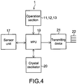
- Fig. 4 is a block diagram showing an electrical structure of the input apparatus 1.
- the MPU 19 includes a built-in volatile or nonvolatile memory requisite therefor.
- the MPU 19 is input with a detection signal from the sensor unit 17, an operation signal from the operation section, and the like, and executes various calculations in order to generate control signals of the first movement information, the movement restriction information, and the execution information in response to those input signals.
- the first movement information is information on an angular velocity, an acceleration, a velocity value, coordinates, or the like of the input apparatus 1 for moving the pointer 2 on the screen 3.
- the movement restriction information is information indicating whether the button 13 has been pressed or information on coordinates of an area 4A indicated by the pointer 2 out of a plurality of areas 4A.
- the execution information is information for executing the icon 4 indicated by the pointer 2 on the screen 3 by the pointer 2, like information indicating whether the button 12 has been double-clicked, for example.
- the crystal oscillator 20 generates clocks and supplies them to the MPU 19.
- the batteries 14 dry cell batteries, rechargeable batteries, and the like are used.
- the transmitting device 21 transmits control signals (input information) generated in the MPU 19 as RF radio signals to the control apparatus 40 via the antenna 22.
- Fig. 5 is a perspective diagram showing the sensor unit 17.
- the sensor unit 17 includes an acceleration sensor unit 16 for detecting accelerations in different angles such as along two orthogonal axes (X axis and Y axis).
- the acceleration sensor unit 16 includes two sensors, that is, a first acceleration sensor 161 and a second acceleration sensor 162.
- the sensor unit 17 further includes an angular velocity sensor unit 15 for detecting angular accelerations about the two orthogonal axes.
- the angular velocity sensor unit 15 includes two sensors, that is, a first angular velocity sensor 151 and a second angular velocity sensor 152.
- the acceleration sensor unit 16 and the angular velocity sensor unit 15 are packaged and mounted on a circuit board 25.
- first angular velocity sensor 151 and the second angular velocity sensor 152 a vibration gyro sensor for detecting Coriolis force in proportion to an angular velocity is used.
- first acceleration sensor 161 and the second acceleration sensor 162 any sensor such as a piezoresistive sensor, a piezoelectric sensor, or a capacitance sensor may be used.
- the sensor unit 17 is incorporated into the casing 10 such that a surface of the circuit board 25 on which the acceleration sensor unit 16 and the angular velocity sensor unit 15 are mounted becomes substantially parallel to an X'-Y' plane.
- the sensor units 16 and 15 each detect physical amounts with respect to the two axes, that is, the X axis and the Y axis.
- a coordinate system that moves along with the input apparatus 1, that is, a coordinate system fixed to the input device 1 will be represented by the X' axis, Y' axis, and Z' axis.
- a coordinate system stationary on earth that is an inertial coordinate system will be represented by the X axis, Y axis, and Z axis.
- a rotational direction about the X' axis is sometimes referred to as pitch direction
- a rotational direction about the Y' axis is sometimes referred to as yaw direction
- a rotational direction about the Z' axis is sometimes referred to as roll direction.
- Fig. 6 is a diagram showing an example of the screen 3 displayed on the display apparatus 5.
- Examples of the display apparatus 5 include a liquid crystal display and an EL (ElectroLuminescence) display, but are not limited thereto.
- the display apparatus 5 may alternatively be an apparatus integrally formed with a display and capable of receiving television broadcasts and the like. Unless stated otherwise, to help understand descriptions below, the UI as an operation target of the input apparatus 1 will be described as being the pointer 2 (pointer).
- UIs such as the icons 4 and the pointer 2 are displayed.
- the icons are images representing, on the screen 3, functions of programs, execution commands, file contents, and the like of the computer.
- the areas 4A are respectively disposed so as to surround the icons 4.
- the button 13 is pressed when the pointer 2 is indicating the area 4A, the pointer 2 is moved so as to indicate the icon 4 inside the area 4A, and the movement of the pointer 2 is restricted at that position.
- X-axis direction a horizontal direction
- Y-axis direction a vertical direction
- Fig. 7 is a diagram showing a state where a user is holding the input apparatus 1.
- the input apparatus 1 may include, in addition to the buttons 11, 12, and 13, operation sections including various operation buttons such as those provided to a remote controller for operating a television or the like and a power switch, for example.
- Input information generated when the user moves the input apparatus 1 in the air or operates the operation section while holding the input apparatus 1 as shown in the figure is output to the control apparatus 40, and the control apparatus 40 controls the UI.
- FIGS. 8 are explanatory diagrams therefor.
- the user holds the input apparatus 1 so as to aim the buttons 11 and 12 side of the input apparatus 1 at the display apparatus 5 side.
- the user holds the input apparatus 1 so that a thumb is located on an upper side and a pinky is located on a lower side as in handshakes.
- the circuit board 25 (see Fig. 5 ) of the sensor unit 17 is close to being in parallel with the screen 3 of the display apparatus 5, and the two axes as detection axes of the sensor unit 17 respectively correspond to the horizontal axis (X axis) and the vertical axis (Y axis) on the screen 3.
- the position of the input apparatus 1 as shown in Figs. 8A and 8B is referred to as reference position.
- the control apparatus 40 controls display of the pointer 2 so as to move the pointer 2 in the Y-axis direction.
- the control apparatus 40 controls display of the pointer 2 so as to move the pointer 2 in the X-axis direction.
- the MPU 19 of the input apparatus 1 calculates the velocity values in the yaw and pitch directions based on the detection values detected by the sensor unit 17 in accordance with the program stored in the built-in nonvolatile memory. In this case, mainly the MPU 19 of the input apparatus 1 calculates the velocity information.
- a dimension of an integration value (velocity) of biaxial acceleration values detected by the acceleration sensor unit 16 is used in principle. Input information of the velocity dimension is transmitted to the control apparatus 40.
- the input apparatus 1 transmits, as the input information, physical amounts detected by the sensor unit 17 to the control apparatus 40.
- the MPU 35 of the control apparatus 40 calculates, in accordance with the program stored in the ROM 37, the velocity values in the yaw and pitch directions based on the received input information, and performs display so as to move the pointer 2 in accordance with the velocity values (see Fig. 14 ).
- the control apparatus 40 converts a displacement in the yaw direction per unit time into a displacement amount of the pointer 2 on the X axis on the screen 3, and converts a displacement in the pitch direction per unit time into a displacement amount of the pointer 2 on the Y axis on the screen 3, to thus move the pointer 2.
- the MPU 35 of the control apparatus 40 adds an n-th velocity value that has been supplied to a (n-1)-th velocity value that has been supplied. Accordingly, the n-th velocity value that has been supplied corresponds to the displacement amount of the pointer 2, and coordinate information of the pointer 2 on the screen 3 is generated. In this case, mainly the MPU 35 of the control apparatus 40 calculates the coordinate information.
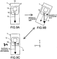
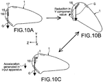
- Figs. 9 and 10 are explanatory diagrams therefor.
- Figs. 9 are diagrams showing the input apparatus 1 seen from the Z direction.
- Figs. 10 are diagrams showing the input apparatus 1 seen from the X direction.
- Fig. 9A the input apparatus 1 is in the reference position and is held still. At this time, an output of the first acceleration sensor 161 is substantially 0, and an output of the second acceleration sensor 162 is an output corresponding to a gravity acceleration G.
- Fig. 9B for example, in a state where the input apparatus 1 is tilted in the roll direction, the first and second acceleration sensors 161 and 162 respectively detect acceleration values of tilt components of the gravity acceleration G.
- the first acceleration sensor 161 detects the acceleration in the X-axis direction even when the input apparatus 1 is not actually moved in the X-axis direction in particular.
- the state shown in Fig. 9B is equivalent to a state where, when the input apparatus 1 is in the reference position as shown in Fig. 9C , the acceleration sensor unit 16 has received inertial forces Ix and Iy as respectively indicated by arrows with broken lines, thus being undistinguishable by the acceleration sensor unit 16.
- the acceleration sensor unit 16 judges that an acceleration in a downward lefthand direction as indicated by an arrow is applied to the input apparatus 1 and outputs a detection signal different from the actual movement of the input apparatus 1.
- the input apparatus 1 of this embodiment uses the angular velocity values detected by the angular velocity sensor unit 15 to calculate the velocity values of the input apparatus 1.
- Fig. 11 is a flowchart showing the operation.
- Power of the input apparatus 1 is turned on.
- the user turns on a power switch or the like provided to the input apparatus 1 or the control apparatus 40 to turn on the power of the input apparatus 1.
- biaxial acceleration signals (first and second acceleration values a x and a y ) are output from the acceleration sensor unit 16 (Step 101a) to be supplied to the MPU 19.
- the acceleration signals are signals corresponding to the position of the input apparatus 1 at a point when the power is turned on (hereinafter, referred to as initial position).
- the initial position is the reference position.
- a position at which the entire amount of the gravity acceleration is detected in the X-axis direction that is, a position at which the output of the first acceleration sensor 161 is the acceleration value corresponding to the gravity acceleration and the output of the second acceleration sensor 162 is 0 is also possible.
- a position tilted as shown in Fig. 9B is also possible.
- the MPU 19 of the input apparatus 1 obtains the acceleration signals (a x , a y ) from the acceleration sensor unit 16 every predetermined number of clocks. Upon obtaining the second and subsequent acceleration signals (a x , a y ), the MPU 19 performs the following calculation to remove the gravitational effect.
- a corx a x ⁇ a refx
- a cory a y ⁇ a refy
- a refx and a refy will be referred to as reference acceleration value on the X axis and reference acceleration value on the Y axis (first reference acceleration value and second reference acceleration value), respectively.
- a refx and a refy used in the first calculation of Step 102a since turning on the power are acceleration signals a x and a y detected right after the power is turned on.
- the MPU 19 calculates a first velocity value V x and a second velocity value V y by respectively adding the first and second correction acceleration values a corx and a cory , that is, by an integration operation (Step 115).
- V x t V x t ⁇ 1 + a corx
- V y t V y t ⁇ 1 + a cory
- V x (t) and V y (t) represent the currently-obtained velocity values and V x (t-1) and V y (t-1) represent previous velocity values.
- biaxial angular velocity signals (first and second angular velocity values ⁇ x , ⁇ y ) are output from the angular velocity sensor unit 15 (Step 101b) to be supplied to the MPU 19.
- the MPU 19 calculates the angular acceleration values (first angular acceleration value ⁇ x and second angular acceleration value ⁇ y ) by a derivation operation (Step 102b).
- the MPU 19 judges whether absolute values
- a threshold value Th1 a threshold value
- the MPU 19 uses the first reference acceleration value a refx as it is and does not update it (Step 104).
- the MPU 19 uses the second reference acceleration value a refy as it is and does not update it (Step 107).
- a value close to 0 is set as the threshold value Th1.
- the threshold value Th1 takes into account the angular velocity values that are detected due to a hand movement of the user, a DC offset, or the like even when the user is consciously holding the input apparatus 1 still.
- the pointer 2 is prevented from being moved during display due to a hand movement or a DC offset in the case where the user is consciously holding the input apparatus 1 still.
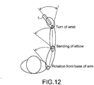
- Fig. 12 is a top view of the user operating the input apparatus 1.
- the operation is made by at least one of a rotation from a base of an arm, bending of an elbow, and a turn of a wrist. Therefore, generation of the acceleration leads to generation of the angular acceleration.
- the acceleration is assumed to be subservient to the angular acceleration in the same direction as the acceleration. Therefore, by the MPU 19 monitoring the second angular acceleration value
- the MPU 19 judges that the input apparatus 1 is moving in the yaw direction. In this case, the MPU 19 does not update the first reference acceleration value a refx and consequently does not correct the first correction acceleration value a corx , and continues on with the integration operation of Equation (3) based on a corx .
- the MPU 19 judges that the input apparatus 1 is moving in the pitch direction. In this case, the MPU 19 does not update the second reference acceleration value a refy and consequently does not correct the second correction acceleration value a cory , and continues on with the integration operation of Equation (4) based on a cory .
- the MPU 19 judges that the input apparatus 1 is not moved in the yaw direction.
- the MPU 19 updates the first reference acceleration value a refx to the currently-obtained (latest) detection value a x , to thereby correct the first correction acceleration value a corx using Equation (1) (Step 105).
- the latest detection value a x is, in other words, a detection value obtained while the input apparatus 1 is held almost still, thus being a component value by the gravity acceleration.
- the MPU 19 judges that the input apparatus 1 is not moved in the pitch direction. In this case, the MPU 19 updates the second reference acceleration value a refy to the currently-obtained (latest) detection value a y , to thereby correct the second correction acceleration value a cory using Equation (2) (Step 108).
- the threshold values in both the yaw direction and the pitch direction have been set to the same value Th1. However, different threshold values may be used for those directions.
- the MPU 19 can also monitor the angular velocity values ⁇ x and ⁇ y to correct the velocity values calculated in Equations (3) and (4). Based on the same idea as that of Fig. 12 , assuming that generation of the velocity leads to generation of the angular velocity, it can be assumed that the velocity is subservient to the angular velocity in the same direction as the velocity.
- the MPU 19 judges that the input apparatus 1 is moving in the yaw direction. In this case, the MPU 19 does not correct the first velocity value V x (Step 110). The same holds true for the absolute value of the first angular velocity value
- the threshold value Th2 also only needs to be set in the same manner as the threshold value Th1.
- the MPU 19 judges that the input apparatus 1 is not moved in the yaw direction. In this case, the MPU 19 corrects the first velocity value V x so as to reset it to 0, for example (Step 111). The same holds true for the absolute value of the first angular velocity value
- the MPU 19 outputs the velocity values V x and V y in both directions as described above, and the transmitting device 21 outputs to the control apparatus 40 the input information on the velocity values (Step 116).
- the MPU 35 of the control apparatus 40 is input with the velocity values V x and V y as the input information (first movement information) (Step 117).
- the MPU 35 generates coordinate values X and Y of the pointer 2 shown in Equations (5) and (6) below, that correspond to the velocity values V x and V y (Step 118), and controls display so as to move the pointer 2 on the screen 3 (Step 119).
- the reference acceleration values a refx and a refy are updated and the correction acceleration values a corx and a cory are corrected when the input apparatus 1 is held almost still, with the result that the gravitational effect with respect to the acceleration sensor unit 16 can be suppressed.
- the correction acceleration values a corx and a cory are corrected using Equations (1) and (2) upon update of the reference acceleration values a refx and a refy , a DC level is also corrected, thereby solving the problem regarding the DC offset.
- the velocity values are corrected so as to be reset to 0 when the input apparatus 1 is held almost still, integration errors can also be suppressed. When an integration error is generated, a phenomenon in which the pointer 2 moves on the screen 3 irrespective of the fact that the user has stopped moving the input apparatus 1 occurs.
- the first reference acceleration value a refx and the second reference acceleration value a refy are updated individually, when even one of the angular acceleration values in the yaw direction and the pitch direction becomes smaller than the threshold value, a correction thereof is performed. Therefore, it is possible to update the first reference acceleration value a refx or the second reference acceleration value a refy with a time interval short enough for practical use. The same holds true for the individual corrections of the first velocity value V x and the second velocity value V y .
- Fig. 13 is an explanatory diagram to help understand the above description.
- Fig. 13 shows a trajectory of the input apparatus 1 seen from a plane formed by the X axis and the Y axis.
- V x is reset to 0 if the angular velocity value ⁇ y in the yaw direction is substantially 0 (smaller than the threshold value Th2).
- V y is reset to 0 if the angular velocity value ⁇ x in the pitch direction is substantially 0 (smaller than the threshold value Th2).
- Fig. 14 is a flowchart showing another embodiment described above.
- the input apparatus 1 outputs, as the input information, to the control apparatus 40, the biaxial acceleration signals and biaxial angular velocity signals output from the sensor unit 17.
- the MPU 35 of the control apparatus 40 executes Steps 102a and 102b to 115 shown in Fig. 11 in Steps 204 to 218. Because details thereof are the same as that of Fig. 11 , descriptions thereof will be omitted.
- Fig. 15 is a flowchart of the operation of selecting and executing the icon 4 on the screen 3 using the input apparatus 1.
- Fig. 16 is a partially enlarged diagram of the screen 3 for explaining steps of restricting the movement of the pointer 2 in the flowchart of Fig. 15 .
- Step 301 based on the signal from the input apparatus 1 received by the receiver device 38, the MPU 35 of the control apparatus 40 judges whether the button 13 has been pressed (a movement recognition function (gyro function) of the input apparatus 1 has become ineffective) (Step 301).
- Step 301 When the button 13 has been pressed in Step 301 (when the movement recognition function of the input apparatus 1 is ineffective), it is judged whether the pointer 2 is indicating the area 4A around the icon 4 (Step 302).
- the processing is ended.
- the pointer 2 is indicating the area 4A as indicated by the arrow in a dotted line of Fig. 16
- the pointer 2 is moved so that the pointer 2 indicates the icon 4 as indicated by the arrow in a solid line of Fig. 16 , and the movement of the pointer 2 is restricted (stopped) at that position (Step 303).
- the movement is controlled so that the pointer 2 is moved to the center of the icon 4 in accordance with the coordinates (X, Y) thereof, for example.
- a state where the pointer 2 is indicating the area 4A is easily shifted to a state where the icon 4 is indicated.
- the icon 4 indicated is set to be in a selected state (Step 304).
- the icon 4 may be colored black or a design of the icon 4 may be changed so that it can be seen that the icon 4 has been selected, for example.
- Step 305 it is judged whether the button 13 is in the pressed state (the movement recognition function of the input apparatus 1 is ineffective) and the button 11 is double-clicked.
- Step 305 When, in Step 305, the button 13 is in the pressed state (the movement recognition function of the input apparatus 1 is ineffective) and the button 11 is double-clicked, the icon 4 is executed based on execution information indicating the double-click (Step 306), and the processing is ended.
- Step 305 When, in Step 305, such a condition that the button 13 is pressed (the movement recognition function of the input apparatus 1 is ineffective) and the button 11 is double-clicked is not satisfied, it is judged whether the button 13 is in the pressed state (the movement recognition function of the input apparatus 1 is ineffective) (Step 307).
- Step 307 When the movement recognition function of the input apparatus 1 is ineffective in Step 307, the icon 4 is in a selected state, so the processing returns to Step 305.
- Step 307 When the button 13 is not in the pressed state (the movement recognition function of the input apparatus 1 is ineffective) in Step 307 (form of restriction cancel information), the selected state of the icon 4 is canceled (Step 308) and the processing is ended.
- the control apparatus 40 input with, when the button 13 is pressed while the pointer 2 is indicating the area 4A around the icon 4 on the screen 3 as indicated by the arrow in a dotted line of Fig. 16 , a signal indicating that the button 13 has been pressed and a signal of coordinate information of the pointer 2 at that time is provided, and the control apparatus 40 performs movement control so that the pointer 2 indicates the icon 4 as indicated by the arrow in a solid line of Fig. 16 based on those signals. Therefore, even when the pointer 2 is not directly indicating the icon 4, indicating the area 4A around the icon 4 can lead to indication of the icon 4, and the operability in selecting the icon 4 on the screen 3 by the pointer 2 can thus be improved.
- the input apparatus 1 including the button 13 is used by swinging it at a position distant from the display apparatus 5 as shown in Figs. 8 , the influence of a hand movement can be eliminated and the icon 4 can be reliably selected.
- the input apparatus 1 includes the button 13, by pressing the button 13 while the pointer 2 is indicating a position on the screen 3 other than the icons 4 and the surrounding areas 4A, for example, the function of recognizing the movement of the input apparatus 1 can be made ineffective. In other words, an operation corresponding to a "lift" operation of a mouse in the related art can be easily realized.
- Fig. 17 is a perspective diagram of an input apparatus 1' of this embodiment.
- the input apparatus 1' includes a scroll dial button 13' in place of the button 13 shown in Fig. 2 .
- the scroll dial button 13' can be pressed in a first direction R1 so as to be pressed into the casing 10, and can be rotated in a second direction R2 and a third direction R3.
- Figs. 18 and 19 are diagrams for illustrating a method of selecting the icon 4 using the scroll dial button 13'.
- Fig. 20 is a flowchart illustrating the operation of selecting and executing the icon 4. It should be noted that Steps 301 to 304 and 305 to 308 are the same as those of the above embodiment, so descriptions thereof will be omitted.
- Step 304 in a state where the icon 4(1), for example, is selected (Step 304), it is judged whether the scroll dial button 13' has been rotated in the second direction R2 (Step 401).
- Step 401 When the scroll dial button 13' is rotated in the second direction R2 in Step 401, based on the rotational amount thereof as second movement information, the pointer 2 is moved to the icon 4(2), the icon 4(3), or the like as shown in Fig. 18 (Step 402), and the icon 4(2), the icon 4(3), or the like is set to be in the selected state (Step 403). Then, the process advances to Step 305.
- Step 404 it is judged whether the scroll dial button 13' has been rotated in the third direction R3 (Step 404).
- Step 404 When the scroll dial button 13' has been rotated in the third direction R3 in Step 404, based on the rotational amount thereof, the pointer 2 is moved to the icon 4(2), the icon 4(3), or the like as shown in Fig. 19 (Step 405), and the icon 4(2), the icon 4(3), or the like is set to be in the selected state (Step 406). Then, the process advances to Step 305.
- Step 404 When the scroll dial button 13' is not rotated in the third direction R3 in Step 404, the process advances to Step 305.
- the input apparatus 1' includes the scroll dial button 13'
- the control apparatus 40 includes the receiver device 38 for receiving the second movement information of the scroll dial button 13' and the MPU 35 for controlling the pointer 2 to move from the selected icon 4(1) to another icon 4(2) in order, based on the second movement information.
- the scroll dial button 13' is rotated in the second direction R2 in the state where the icon 4(1) is selected by the pointer 2 (Step 304)
- the information on the rotational amount of the scroll dial button 13' as the second movement information is input to the control apparatus 40, and based on the second movement information, the MPU 35 can move the pointer 2 from the selected icon 4(1) to another icon 4(2) or the like in the order shown in Fig. 18 .
- the pointer 2 can be moved to the icon 4(1) in the order shown in Fig. 18 or 19 , whereby the desired icon 4(1) can be easily selected.
- Fig. 21 is a perspective diagram of an input apparatus of this embodiment.
- an input apparatus 200 includes a ball-like button 130 in place of the button 13 shown in Fig. 2 .
- the button 130 can be pressed in the first direction R1 so as to be pressed into the casing 10, and can rotate in various directions such as the second direction R2, the third direction R3, a fourth direction R4, and a fifth direction R5.
- Fig. 22 is a diagram for illustrating a method of selecting the icon 4 using the button 130.
- the button 130 of the input apparatus 200 is rotated in the fifth direction R5 in a state where the icon 4(1) is selected by the pointer 2, the icon 4(2) is selected.
- the button 130 is rotated in the third direction R3, the icon 4(3) is selected.
- the button 130 is rotated in a sixth direction R6 between the third direction R3 and the fifth direction R5, the icon 4(4) is selected.
- the pointer 2 can be moved to any of other arbitrary icons 4(2) to 4(4) and the like around the icon 4(1).
- the button 130 can be rotated in various directions, a change can easily be made to an icon wished to be selected, in a shortest distance.
- Fig. 23 is a plan view of the mouse.
- the function of the button 13 may be provided to a mouse 300 of the related art that includes a left button 301, a right button 302, a scroll dial button 303, and the like.
- a function of switching effectiveness/ineffectiveness of a function of recognizing a movement of the mouse 300, which is the function of the button 13 may be provided to the right button 302 or the scroll dial button 303.
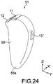
- Fig. 24 is a perspective diagram showing an input apparatus 51.
- Fig. 25 is a side view of the input apparatus 51 seen from the scroll dial button 13' side.
- descriptions on components, functions, and the like similar to those of the input apparatus 1 according to the embodiment shown in Fig. 2 and the like will be simplified or omitted, and points different therefrom will mainly be described.
- a casing 50 of the input apparatus 51 includes a partial sphere or partial quadric surface 50a provided at a predetermined position on a surface of the casing 50.
- the partial sphere or quadric surface (50a) will be referred to as "lower curved surface” (50a) for convenience.
- the lower curved surface 50a is formed at a position almost opposite to the buttons 11 and 12, that is, a position where, when a user holds the input apparatus 51, a pinky is located closer to the lower curved surface 50a than other fingers.
- the sensor unit 17 is provided on a positive side of the Z' axis with respect to a longitudinal center of the casing 50 in the Z'-axis direction
- the lower curved surface 50a is provided on a negative side of the Z' axis.
- the partial sphere is substantially a hemisphere, but does not necessarily have to be a hemisphere.
- the quadric surface is a curved surface obtained by expanding a 2-dimensional conic curve (quadric curve) into a 3-dimensional conic curve. Examples of the quadric surface include an ellipsoid surface, an ellipsoid paraboloid surface, and a hyperbolic surface.
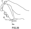
- a user can easily operate the input apparatus 51 while causing the lower curved surface 50a of the input apparatus 51 as a fulcrum to abut on a table, a chair, a floor, a knee or thigh of a user, and the like (hereinafter, referred to as abutment target object 49). That is, even in the state where the lower curved surface 50a of the input apparatus 51 is abutted on the abutment target object 49, the user can easily tilt the input apparatus 51 in diverse angles, thereby enabling delicate operations such as placing the pointer on the icon.
- Fig. 26 is a diagram showing the state where the user operates the input apparatus 51 while causing the lower curved surface 50a to abut on the knee.
- erroneous operations due to a shake of a hand which cannot be suppressed by a shake correction circuit, can be prevented from occurring, and the user is free from fatigue that is caused when the user operates the input apparatus 51 in the air.
- Fig. 27 is a perspective diagram of an input apparatus according to still another embodiment of the present invention.
- a casing 60 of an input apparatus 61 includes, similar to the input apparatus 51 shown in Figs. 24 and 25 , a lower curved surface 60a constituted of a partial sphere.
- a plane perpendicular to a maximum length direction (Z'-axis direction) of the casing 60 of the input apparatus 61 and is in contact with the lower curved surface 60a (hereinafter, referred to as lower end plane 55 for convenience) is substantially parallel to a plane formed by the X axis and the Y axis (see Fig. 5 ) as detection axes of the angular velocity sensor unit 15 (X-Y plane).
- the input apparatus 61 With the structure of the input apparatus 61 as described above, in a case where an operation is made by the user while the lower curved surface 60a is abutted on the lower end plane 55, angular velocities applied to the input apparatus 61 are input to the angular velocity sensor unit 15 as they are. Thus, an amount of calculation required to obtain detection values from the detection signals from the angular velocity sensor unit 15 can be reduced.
- Fig. 28 is a plan view showing an input apparatus according to yet another embodiment of the present invention.
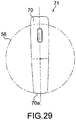
- Fig. 29 is a side view showing the input apparatus.
- a lower curved surface 70a of a casing 70 of an input apparatus 71 is, for example, a partial sphere.
- the lower curved surface 70a is set with a larger curvature radius than the lower curved surfaces 50a and 60a of the input apparatuses 51 and 61 shown in Figs. 24 and 27 .
- the angular velocity sensor unit 15 is provided at a position at which a straight line contained in the X-Y plane formed by the X axis and the Y axis as the detection axes of the angular velocity sensor unit 15 corresponds to a tangent line of a virtually-drawn circle 56 that passes the partial sphere when seen from the X- and Y-axis directions.
- the angular velocity sensor unit 15 may be arranged in the casing 70 such that the X-Y plane of the angular velocity sensor unit 15 is tilted with respect to a longitudinal direction of the input apparatus 71 (see Fig. 28 ).
- Fig. 30 is a plan view of an input apparatus according to still another embodiment of the present invention.
- a sphere as a lower curved surface 80a of a casing 80 of an input apparatus 81 has a curvature radius the same as or close to that shown in Fig. 27 , for example.
- a virtual straight line that passes an intersection of the X axis and the Y axis, which is a center point of the angular velocity sensor unit 15, and is orthogonal to the X axis and the Y axis passes a center point O of a first sphere 62 including the lower curved surface 80a.
- the input apparatus 81 bears the same effect as the input apparatus 71 shown in Fig. 28 .
- the input apparatus 51, 61, 71, or 81 including the partial sphere or the partial quadric surface described above does not necessarily need to be operated by the user while the lower curved surface 50a, 60a, 70a, or 80a thereof is abutted against the abutment target object 49, and may of course be operated in air.
- the processing flow described in Fig. 15 can also be applied to, for example, a case where the pointer has moved to the area 4A to be placed on a first icon and a case of moving to a second icon adjacent to the first icon. Specifically, the processing flow described in Fig. 15 may also be applied to a case where the pointer has moved from the first icon 4 that has been selected to the second icon 4 (or moved to the third or subsequent icon 4).
- the restriction cancel information As a form of the restriction cancel information, the information indicating that the pressing of the button 13, 13', or the like has been released has been taken as an example.
- information indicating that the velocity, acceleration, or angular velocity of the input apparatus 1 has exceeded a threshold value may be used as the restriction cancel information.
- the movement of the pointer 2 may be controlled such that, in a case where, after the pointer 2 is temporarily restrained on the icon 4 and the movement is thus restricted, the user moves the input apparatus at a predetermined velocity, acceleration, angular velocity, or the like, the restraint is released and the pointer 2 is moved away from the icon 4.
- restriction cancel information a case where a certain gesture is made when the user moves the input apparatus 1 while holding the input apparatus 1 is given.
- the movement restriction only needs to be canceled when the gesture of the user matches or is close to gesture information stored in advance in the input apparatus 1 or the control apparatus 40.
- the gesture information is information on the movement of the casing 10 that the user has registered in advance, for example.
- a certain gesture is a movement of swinging the casing 10 a predetermined number of times, a movement of the user signing his/her own autograph, other movements of writing/drawing letters and figures, and the like. Control may also be performed such that, by the certain gesture, the pointer 2 is moved from the first icon currently being restrained upon to the second icon adjacent thereto.
- the input apparatuses 1, 1', 200, 15, and the like of the above embodiments have transmitted the input information to the control apparatus wirelessly, the input information may be transmitted by wire.
- the present invention may also be applied to, for example, a handheld information processing apparatus in which the input apparatus (or 1', 200, 15, etc.), the control apparatus 40, and the display apparatus 5 are integrated.
- the handheld information processing apparatus include a PDA (Personal Digital Assistance), a cellular phone, a portable music player, and a digital camera.
- the pointer 2 that moves on the screen in accordance with the movement of the input apparatus 1, 51, or the like has been represented by an image of an arrow.
- the image of the pointer 2 is not limited to the arrow, and a simple circle, square, and the like, or a character image or other images may be used instead.
- each of the angular velocity sensor unit 15 and the acceleration sensor unit 16 of the sensor unit 17 do not necessarily need to be mutually orthogonal like the X' axis and the Y' axis described above.
- the accelerations respectively projected in the mutually-orthogonal axial directions can be obtained by a calculation that uses a trigonometric function.
- the angular velocities about the mutually-orthogonal axes can be obtained by the calculation that uses the trigonometric function.
- An angle sensor or an angular acceleration sensor may be used instead of the angular velocity sensor unit 15.
- the angle sensor there are a geomagnetic sensor, an image sensor, and the like.
- a change amount of an angle value is detected. Therefore, in this case, the angular velocity value can be obtained by subjecting the angle value to a derivation operation.
- the angular acceleration sensor is constituted of a combination of a plurality of acceleration sensors, and the angular velocity value can be obtained by subjecting the angular acceleration value obtained by the angular acceleration sensor to an integration operation.
- Fig. 11 has shown the calculation method of the velocity values (V x , V y ).
- the MPU 19 may calculate the velocity values (V x , V y ) corresponding to the angular velocity values detected by the angular velocity sensor unit 15.
- the velocity values corresponding to the angular velocity values are velocity values calculated by a predetermined operational expression (function of angular velocity values and velocity values), or velocity values read out from the memory using a lookup table.
- the acceleration values (a x , a y ) obtained by the acceleration sensor unit 16 do not have to be used.
- display has been controlled such that the pointer 2 is drawn to the icon 4.
- display may be controlled such that, when the pointer 2 is placed inside the area 4A, the icon 4 is displayed with emphasis.
- the display with emphasis means that at least one of a design and size of the icon 4 is changed.
- the design of the icon 4 refers to a color, pattern, shape, and the like.
- display may also be controlled such that the size of the icon 4 is made larger than before so that a part of the icon 4 is positioned on the coordinates of the pointer 2 (this is included in the emphasis display of the icon 4).
- control of moving the entire icon 4 may be executed such that, when the pointer 2 is positioned inside the area 4A, a predetermined coordinate position inside the image of the icon 4 is positioned at a coordinate position of the pointer 2.
- the pointer 2 when the pointer 2 is positioned inside the area 4A, the pointer 2 may be displayed with emphasis.
- the pointer 2 may be displayed with emphasis.
- at least one of a design and size of the pointer 2 only needs to be changed, like the pointer 2 is extended to the icon 4, for example.
- the movement of the pointer 2 may also be controlled such that a movement sensitivity of the pointer 2 is improved as the pointer 2 comes closer to the coordinates of the icon 4. The closer the position of the pointer 2 is to the coordinates of the icon 4, the more slightly the user needs to move the input apparatus 1 to move the pointer 2 a large distance.
- the MPU 35 of the control apparatus 40 only needs to calculate, as new velocity values, ( ⁇ V x , ⁇ V y ) that are values obtained by multiplying the velocity values (V x , V y ) for moving the icon 4 by coefficients ( ⁇ , ⁇ ). Then, the MPU 35 only needs to generate coordinate values of the pointer 2 based on the new velocity values.
- the coefficients ( ⁇ , ⁇ ) only need to be real numbers or integers.
- a function in which the coefficients ( ⁇ , ⁇ ) decrease as the pointer 2 moves farther away from coordinate values of a center of the image of the icon 4 (or coordinate values at a predetermined position within the image of the icon 4) on the screen be used.
- the function may be a linear function, a function of quadratic or more, or an exponent function.
- the movement sensitivity in either one of the X-axis direction and the Y-axis direction on the screen may be variable.
- the degree by which the pointer 2 is drawn to the icon 4 may be changed in accordance with a use frequency (e.g., use count) of the icon 4 by the user.
- a use frequency e.g., use count
- the MPU 35 of the control apparatus 40 counts a use count of the first icon and a use count of the second icon from among the plurality of icons 4, and stores those count values in the nonvolatile memory.
- the use count of the first icon is equal to or smaller than predetermined, even when a distance of the pointer 2 from the coordinate values of the first icon and a distance of the pointer 2 from the coordinate values of the second icon used more than a predetermined number of times are the same, the movement sensitivity of the second icon only needs to be set higher than that of the first icon.
- the MPU 35 can variably set the movement sensitivity of the pointer 2 from the coordinate positions of the icons 4, for each of multiple stages into which the use frequency is divided.
- the use count may be, for example, the number of times an operation of executing a file, which is an operation of opening a file corresponding to the icon or activating an application program corresponding to the icon, is carried out.
- the present invention is not limited thereto, and an icon selection operation, a drag operation, a copy operation, or a combination of those may be included in the use count.
- An information processing apparatus includes an input means for inputting movement information for moving on a screen a pointer for selecting a target object from a plurality of target objects displayed on a screen, and a control means for controlling the movement of the pointer on the screen by multiplying the movement information input by the input means by a coefficient that changes in accordance with a distance between the target object and the pointer on the screen.
- an information processing apparatus includes an input means for inputting movement information for moving on a screen a pointer for selecting a target object from a plurality of target objects displayed on the screen, and a control means for controlling the movement of the pointer on the screen by multiplying the movement information input by the input means by a coefficient that changes in accordance with a use frequency of the target object.
- the information processing apparatus may be the input apparatus 1, the control apparatus 40, or the handheld information processing apparatus that includes a display as well as a combination of those two.
Landscapes
- Engineering & Computer Science (AREA)
- General Engineering & Computer Science (AREA)
- Theoretical Computer Science (AREA)
- Human Computer Interaction (AREA)
- Physics & Mathematics (AREA)
- General Physics & Mathematics (AREA)
- Position Input By Displaying (AREA)
- User Interface Of Digital Computer (AREA)
Claims (7)
- Informationsverarbeitungsvorrichtung, aufweisend:ein Anzeigemittel (5), das dazu in der Lage ist, auf einem Bildschirm (3) eine Vielzahl von Zielobjekten (4) und einen Zeiger (2) zum Auswählen eines Zielobjekts (4) aus der Vielzahl von Zielobjekten anzuzeigen;eine Eingabevorrichtung (1; 1'; 200), aufweisend:- einen ersten Betätigungsabschnitt, angepasst zum Eingeben von ersten Bewegungsinformationen, durch eine Sensoreinheit (17) der Eingabevorrichtung (1; 1'; 200), zum Bewegen des Zeigers (2) auf dem Bildschirm (3),- einen zweiten Betätigungsabschnitt, angepasst zum Eingeben von Bewegungseinschränkungsinformationen zum Bewegen, wenn der Zeiger auf einen vorbestimmten Bereich (4A) um das Zielobjekt (4) herum auf dem Bildschirm zeigt, des Zeigers (2), so dass der Zeiger auf das Zielobjekt zeigt, und Einschränken der Bewegung des Zeigers auf diese Position,- einen dritten Betätigungsabschnitt, angepasst zum Eingeben von Ausführungsinformationen zum Ausführen, durch den Zeiger, des Zielobjekts, auf das der Zeiger auf dem Bildschirm zeigt; undein Steuerungsmittel zum Durchführen einer Bewegungssteuerung des Zeigers (2) und einer Ausführungssteuerung des Zielobjekts (4) basierend auf den ersten Bewegungsinformationen, den Bewegungseinschränkungsinformationen, und den durch die Eingabevorrichtung (1; 1'; 200) eingegebenen Ausführungsinformationen, wobeidie Eingabevorrichtung (1; 1'; 200) als zweiten Betätigungsabschnitt eine Taste (13; 13'; 130) aufweist, die ferner angepasst ist zum Eingeben von Einschränkungsabbruchinformationen zum Abbrechen der Einschränkung der Bewegung des Zeigers (2), wobei das Steuerungsmittel dazu angepasst ist, die Bewegungssteuerung des Zeigers basierend auf den Einschränkungsabbruchinformationen durchzuführen, wobei die Taste (13; 13'; 130) der Eingabevorrichtung (1; 1'; 200) durch einen Benutzer betätigt wird, um eine Umschaltung durchzuführen, ob oder nicht die Eingabevorrichtung (1; 1'; 200) gelassen wird, eine Bewegung der Eingabevorrichtung (1; 1'; 200) basierend auf die Eingabe des ersten Betätigungsabschnitts zu erkennen; unddas Steuerungsmittel dazu angepasst ist, die Bewegungssteuerung des Zeigers (2) basierend auf, als die Einschränkungsabbruchinformationen, eines ein von dem Benutzer verursachten Betätigungssignals des Schalters (13; 13'; 130) durchzuführen, dadurch gekennzeichnet, dassdie Eingabevorrichtung als den dritten Betätigungsabschnitt eine zweite Taste (11) aufweist und eine dritte Taste (12) und ein Gehäuse (50) mit einer länglichen Form in einer Längsrichtung (Z') aufweist, wobei der zweite Betätigungsabschnitt (13), der dritte Betätigungsabschnitt (11), und die dritte Taste (12) an einem oberen Abschnitt des Gehäuses (10) vorgesehen sind, wobei das Gehäuse eine untere gekrümmte Fläche (50a) aufweist, wobei die untere gekrümmte Fläche (50a) ein Drehpunkt ist, der dazu konfiguriert ist, während einer Betätigung der Eingabevorrichtung durch einen Benutzer an ein Anstoßzielobjekt (49) anstoßend zu sein, wobei die untere gekrümmte Fläche (50a) eine partielle Kugelfläche oder eine partielle Quadrikfläche ist, wobei der zweite Betätigungsabschnitt eine Scrolldrehtaste (13') ist, wobei die Sensoreinheit (17) in Bezug auf eine Längsmitte des Gehäuses auf einer positiven Seite der Längsachse (Z') vorgesehen ist, und wobei die untere gekrümmte Fläche (50a) auf einer negativen Seite der Längsachse (Z') vorgesehen ist.
- Informationsverarbeitungsvorrichtung nach Anspruch 1, dadurch gekennzeichnet, dass:die Eingabevorrichtung (1; 1'; 200) angepasst ist zum Eingeben von zweiten Bewegungsinformationen zum Bewegen, wenn die Bewegung des Zeigers (2) auf dem Bildschirm eingeschränkt wird, während der Zeiger auf das Zielobjekt (4) zeigt, des Zeigers von dem Zielobjekt, auf das durch den Zeiger gezeigt wird, zu einem anderen Zielobjekt in einer vorbestimmten Reihenfolge; unddas Steuerungsmittel dazu angepasst ist, die Bewegungssteuerung des Zeigers basierend auf den zweiten Bewegungsinformationen durchzuführen.
- Informationsverarbeitungsvorrichtung nach Anspruch 1 oder 2, dadurch gekennzeichnet, dass
die Eingabevorrichtung (1; 1'; 200) angepasst ist zum Eingeben von dritten Bewegungsinformationen zum Bewegen, wenn die Bewegung des Zeigers (2) eingeschränkt wird, während das Zielobjekt (4) auf dem Bildschirm (3) gezeigt wird, des Zeigers zu einem anderen Zielobjekt, um das Zielobjekt herum, auf das durch den Zeiger gezeigt wird; und
die Steuereinrichtung dazu angepasst ist, die Bewegungssteuerung des Zeigers basierend auf den dritten Bewegungsinformationen durchzuführen. - Informationsverarbeitungsvorrichtung nach Anspruch 2 oder 3,
dadurch gekennzeichnet, dass die Bewegungseinschränkungsinformationen Informationen enthalten zum Bewegen des Zeigers (2), so das der Zeiger auf das andere Zielobjekt (4) zeigt, und Einschränken der Bewegung des Zeigers auf diese Position. - Informationsverarbeitungsvorrichtung nach einem der Ansprüche 1 bis 4, wobei die Eingabevorrichtung (1; 1'; 200) ferner aufweist
einen vierten Betätigungsabschnitt, um zweite Bewegungsinformationen einzugeben, zum Bewegen, wenn die Bewegung des Zeigers (2) eingeschränkt wird, während das Zielobjekt (4) auf dem Bildschirm (3) gezeigt wird, des Zeigers von dem Zielobjekt, auf das durch den Zeiger gezeigt wird, zu einem anderen Zielobjekt in einer vorgegebenen Reihenfolge. - Informationsverarbeitungsvorrichtung nach Anspruch 5, wobei die Eingabevorrichtung ferner dadurch gekennzeichnet, dass
der zweite Betätigungsabschnitt und der vierte Betätigungsabschnitt aus einer einzelnen Scrolldrehtaste (13') bestehen;
der zweite Betätigungsabschnitt dazu angepasst ist, die Eingabe durchzuführen, wenn die Scrolldrehtaste gedrückt wird; und
der vierte Betätigungsabschnitt dazu angepasst ist, die Eingabe durchzuführen, wenn ein Scrollrad der Scrolldrehtaste gedreht wird. - Informationsverarbeitungsvorrichtung nach einem der Ansprüche 1 bis 6, wobei die Eingabevorrichtung (1; 1'; 200) ferner aufweist
einen fünften Betätigungsabschnitt zum Eingeben von dritten Bewegungsinformationen zum Bewegen, wenn die Bewegung des Zeigers (2) eingeschränkt wird, während das Zielobjekt (4) auf dem Bildschirm (3) gezeigt wird, des Zeigers zu einem anderen Zielobjekt, um das Zielobjekt herum, auf das durch den Zeiger gezeigt wird.
Applications Claiming Priority (2)
| Application Number | Priority Date | Filing Date | Title |
|---|---|---|---|
| JP2007152592 | 2007-06-08 | ||
| PCT/JP2008/060489 WO2008149991A1 (ja) | 2007-06-08 | 2008-06-06 | 情報処理装置、入力装置、情報処理システム、情報処理方法及びプログラム |
Publications (3)
| Publication Number | Publication Date |
|---|---|
| EP2157498A1 EP2157498A1 (de) | 2010-02-24 |
| EP2157498A4 EP2157498A4 (de) | 2013-05-15 |
| EP2157498B1 true EP2157498B1 (de) | 2017-05-24 |
Family
ID=40093796
Family Applications (1)
| Application Number | Title | Priority Date | Filing Date |
|---|---|---|---|
| EP08777109.3A Not-in-force EP2157498B1 (de) | 2007-06-08 | 2008-06-06 | Informationsverarbeitungsvorrichtung mit zeiger-steuerung |
Country Status (7)
| Country | Link |
|---|---|
| US (2) | US9141202B2 (de) |
| EP (1) | EP2157498B1 (de) |
| JP (1) | JP5338662B2 (de) |
| KR (1) | KR101466872B1 (de) |
| CN (1) | CN101568896B (de) |
| TW (1) | TWI408572B (de) |
| WO (1) | WO2008149991A1 (de) |
Families Citing this family (36)
| Publication number | Priority date | Publication date | Assignee | Title |
|---|---|---|---|---|
| JP4951570B2 (ja) * | 2008-03-31 | 2012-06-13 | 株式会社日立製作所 | 情報処理装置とその表示方法 |
| US8798956B2 (en) * | 2008-09-30 | 2014-08-05 | Apple Inc. | Method and apparatus for surface sensing input device |
| JP5843762B2 (ja) * | 2009-06-05 | 2016-01-13 | ダッソー システムズ ソリッドワークス コーポレイション | 予測的ターゲットを拡大させるための方法、および、システム |
| US8493344B2 (en) | 2009-06-07 | 2013-07-23 | Apple Inc. | Devices, methods, and graphical user interfaces for accessibility using a touch-sensitive surface |
| JP5535585B2 (ja) | 2009-11-10 | 2014-07-02 | 株式会社ソニー・コンピュータエンタテインメント | プログラム、情報記憶媒体、情報入力装置、及びその制御方法 |
| JP5434638B2 (ja) | 2010-01-29 | 2014-03-05 | ソニー株式会社 | 情報処理装置および情報処理方法 |
| JP5038465B2 (ja) | 2010-05-25 | 2012-10-03 | 任天堂株式会社 | 情報処理プログラム、情報処理装置、情報処理方法および情報処理システム |
| JP5581817B2 (ja) * | 2010-06-03 | 2014-09-03 | ソニー株式会社 | 制御システム、制御装置、ハンドヘルド装置、制御方法及びプログラム。 |
| JP5791256B2 (ja) * | 2010-10-21 | 2015-10-07 | キヤノン株式会社 | 表示制御装置、表示制御方法 |
| US9671880B2 (en) * | 2011-12-22 | 2017-06-06 | Sony Corporation | Display control device, display control method, and computer program |
| KR101872272B1 (ko) * | 2012-02-10 | 2018-06-28 | 삼성전자주식회사 | 제어 기기를 이용한 전자기기의 제어 방법 및 장치 |
| JP5982956B2 (ja) * | 2012-03-30 | 2016-08-31 | 富士通株式会社 | 情報処理装置、情報処理方法、および情報処理プログラム |
| US8881269B2 (en) | 2012-03-31 | 2014-11-04 | Apple Inc. | Device, method, and graphical user interface for integrating recognition of handwriting gestures with a screen reader |
| JP2014052983A (ja) * | 2012-09-10 | 2014-03-20 | Ricoh Co Ltd | 情報処理装置、投影システム及び操作プログラム |
| US20140152558A1 (en) * | 2012-11-30 | 2014-06-05 | Tom Salter | Direct hologram manipulation using imu |
| TWI475476B (zh) * | 2013-01-21 | 2015-03-01 | 宏碁股份有限公司 | 觸碰偵測方法及裝置 |
| EP2770413A3 (de) * | 2013-02-22 | 2017-01-04 | Samsung Electronics Co., Ltd. | Vorrichtung zur Bereitstellung eines Cursors in elektronischen Geräten und Verfahren dafür |
| JP2015022496A (ja) * | 2013-07-18 | 2015-02-02 | 富士通株式会社 | 制御プログラム、制御方法及び制御装置 |
| EP3037941B1 (de) * | 2013-08-20 | 2018-08-01 | Sony Interactive Entertainment Inc. | Cursor-positionssteuerungsvorrichtung, cursor-positionssteuerungsverfahren, programm und informationsspeichermedium |
| CN103617002A (zh) * | 2013-12-16 | 2014-03-05 | 深圳市理邦精密仪器股份有限公司 | 一种触控界面的实现方法及装置 |
| JP2015127872A (ja) * | 2013-12-27 | 2015-07-09 | ソニー株式会社 | 制御装置、制御方法、及び、プログラム |
| KR102161677B1 (ko) * | 2014-01-03 | 2020-10-05 | 삼성전자주식회사 | 원격 제어 장치 및 그의 제어 방법 |
| CN103997668B (zh) | 2014-02-25 | 2017-12-22 | 华为技术有限公司 | 移动设备选中显示方法及终端设备 |
| CN103995585B (zh) * | 2014-05-04 | 2017-12-08 | 广东威创视讯科技股份有限公司 | 显示大墙的手势控制设备与方法 |
| CN104571855B (zh) * | 2014-12-16 | 2018-03-23 | 上海卓易科技股份有限公司 | 一种控制信息处理方法及终端 |
| JP2016146104A (ja) * | 2015-02-09 | 2016-08-12 | 富士ゼロックス株式会社 | 入力システム、入力装置およびプログラム |
| CN104869470A (zh) * | 2015-05-25 | 2015-08-26 | 广州创维平面显示科技有限公司 | 根据遥控光标位置自动捕获ui焦点的实现方法及系统 |
| CN105224215A (zh) * | 2015-08-28 | 2016-01-06 | 小米科技有限责任公司 | 终端控制方法及装置 |
| CN106095303B (zh) * | 2016-05-31 | 2021-03-23 | 周奇 | 一种应用程序操作方法及装置 |
| DK201670580A1 (en) | 2016-06-12 | 2018-01-02 | Apple Inc | Wrist-based tactile time feedback for non-sighted users |
| JP7043166B2 (ja) * | 2016-09-21 | 2022-03-29 | 株式会社デンソーテン | 表示制御装置、表示制御システム及び表示制御方法 |
| SG11202002795WA (en) * | 2017-10-10 | 2020-04-29 | Razer Asia Pacific Pte Ltd | Method and apparatus for analyzing mouse gliding performance |
| US10996761B2 (en) | 2019-06-01 | 2021-05-04 | Apple Inc. | User interfaces for non-visual output of time |
| EP4195685B1 (de) | 2020-09-08 | 2026-08-05 | Sony Group Corporation | Informationsverarbeitungsvorrichtung und informationsverarbeitungsverfahren |
| CN113190141B (zh) * | 2021-04-27 | 2025-02-07 | 维沃移动通信有限公司 | 显示方法和电子设备 |
| CN114760513A (zh) * | 2022-04-22 | 2022-07-15 | 海信电子科技(武汉)有限公司 | 一种显示设备及光标定位方法 |
Citations (2)
| Publication number | Priority date | Publication date | Assignee | Title |
|---|---|---|---|---|
| US5457448A (en) * | 1993-08-03 | 1995-10-10 | Sony Electronics, Inc. | Self-standing mini remote commander |
| US6130664A (en) * | 1997-02-25 | 2000-10-10 | Alps Electric Co., Ltd. | Input device |
Family Cites Families (20)
| Publication number | Priority date | Publication date | Assignee | Title |
|---|---|---|---|---|
| JPH04102913A (ja) * | 1990-08-22 | 1992-04-03 | Ricoh Co Ltd | カーソル制御方式 |
| JPH07284166A (ja) * | 1993-03-12 | 1995-10-27 | Mitsubishi Electric Corp | 遠隔操作装置 |
| JP3344499B2 (ja) * | 1993-06-30 | 2002-11-11 | 株式会社東芝 | オブジェクト操作支援装置 |
| JPH0736243A (ja) | 1993-07-19 | 1995-02-07 | Canon Inc | カラー画像形成装置 |
| JPH0736243U (ja) | 1993-12-09 | 1995-07-04 | 株式会社東芝 | マンマシン装置 |
| US5564004A (en) * | 1994-04-13 | 1996-10-08 | International Business Machines Corporation | Method and system for facilitating the selection of icons |
| JPH0816353A (ja) * | 1994-06-28 | 1996-01-19 | Sharp Corp | オブジェクト表示拡大方法 |
| US5565888A (en) * | 1995-02-17 | 1996-10-15 | International Business Machines Corporation | Method and apparatus for improving visibility and selectability of icons |
| JPH08314637A (ja) * | 1995-05-22 | 1996-11-29 | Matsushita Electric Ind Co Ltd | 映像表示装置 |
| JPH0916370A (ja) * | 1995-06-29 | 1997-01-17 | Victor Co Of Japan Ltd | 表示オブジェクト選択方式 |
| US5808601A (en) * | 1995-09-12 | 1998-09-15 | International Business Machines Corporation | Interactive object selection pointer method and apparatus |
| US6037933A (en) * | 1996-11-13 | 2000-03-14 | Samsung Electronics Co., Ltd. | TV graphical user interface for providing user access to preset time periods of TV program information |
| US5905497A (en) * | 1997-03-31 | 1999-05-18 | Compaq Computer Corp. | Automatic and seamless cursor and pointer integration |
| US6252579B1 (en) * | 1997-08-23 | 2001-06-26 | Immersion Corporation | Interface device and method for providing enhanced cursor control with force feedback |
| US6724368B2 (en) * | 2001-12-14 | 2004-04-20 | Koninklijke Philips Electronics N.V. | Remote control system and method for a television receiver |
| GB2411452C (en) * | 2004-08-06 | 2008-03-17 | Simon Richard Daniel | Flat and collapsible mouse |
| TWI258098B (en) * | 2004-12-31 | 2006-07-11 | Pixart Imaging Inc | Method and related apparatus for decreasing delay time and power consumption of a wireless mouse |
| JP4238222B2 (ja) * | 2005-01-04 | 2009-03-18 | インターナショナル・ビジネス・マシーンズ・コーポレーション | オブジェクト編集システム、オブジェクト編集方法及びオブジェクト編集プログラム |
| US7647565B2 (en) * | 2005-02-16 | 2010-01-12 | International Business Machines Coporation | Method, apparatus, and computer program product for an enhanced mouse pointer |
| US7927216B2 (en) * | 2005-09-15 | 2011-04-19 | Nintendo Co., Ltd. | Video game system with wireless modular handheld controller |
-
2008
- 2008-06-06 WO PCT/JP2008/060489 patent/WO2008149991A1/ja not_active Ceased
- 2008-06-06 CN CN2008800013150A patent/CN101568896B/zh not_active Expired - Fee Related
- 2008-06-06 KR KR1020097011299A patent/KR101466872B1/ko not_active Expired - Fee Related
- 2008-06-06 EP EP08777109.3A patent/EP2157498B1/de not_active Not-in-force
- 2008-06-06 TW TW97121349A patent/TWI408572B/zh not_active IP Right Cessation
- 2008-06-06 JP JP2009517916A patent/JP5338662B2/ja not_active Expired - Fee Related
- 2008-06-06 US US12/517,505 patent/US9141202B2/en active Active
-
2015
- 2015-07-20 US US14/803,882 patent/US9829998B2/en not_active Expired - Fee Related
Patent Citations (2)
| Publication number | Priority date | Publication date | Assignee | Title |
|---|---|---|---|---|
| US5457448A (en) * | 1993-08-03 | 1995-10-10 | Sony Electronics, Inc. | Self-standing mini remote commander |
| US6130664A (en) * | 1997-02-25 | 2000-10-10 | Alps Electric Co., Ltd. | Input device |
Non-Patent Citations (1)
| Title |
|---|
| RAVIN BALAKRISHNAN ET AL: "The Rockin' Mouse: Integral 3D Manipulation on a Plane", PROCEEDINGS OF THE SIGCHI CONFERENCE ON HUMAN FACTORS IN COMPUTING SYSTEMS; [CONFERENCE ON HUMAN FACTORS IN COMPUTING SYSTEMS], NEW YORK, NY, USA, 22 March 1997 (1997-03-22), pages 1 - 12, XP002257214, ISBN: 978-0-89791-802-2 * |
Also Published As
| Publication number | Publication date |
|---|---|
| US9141202B2 (en) | 2015-09-22 |
| TW200915140A (en) | 2009-04-01 |
| EP2157498A1 (de) | 2010-02-24 |
| US20100039382A1 (en) | 2010-02-18 |
| JPWO2008149991A1 (ja) | 2010-08-26 |
| KR20100019978A (ko) | 2010-02-19 |
| CN101568896B (zh) | 2012-01-11 |
| CN101568896A (zh) | 2009-10-28 |
| US20150331499A1 (en) | 2015-11-19 |
| WO2008149991A1 (ja) | 2008-12-11 |
| US9829998B2 (en) | 2017-11-28 |
| TWI408572B (zh) | 2013-09-11 |
| KR101466872B1 (ko) | 2014-12-01 |
| EP2157498A4 (de) | 2013-05-15 |
| JP5338662B2 (ja) | 2013-11-13 |
Similar Documents
| Publication | Publication Date | Title |
|---|---|---|
| US9829998B2 (en) | Information processing apparatus, input apparatus, information processing system, information processing method, and program | |
| US8199031B2 (en) | Input apparatus, control apparatus, control system, control method, and program therefor | |
| US10747338B2 (en) | Input apparatus, control apparatus, control system, control method, and handheld apparatus | |
| US8576168B2 (en) | Input apparatus, control apparatus, control system, control method, and handheld apparatus | |
| EP2219102B1 (de) | Eingabevorrichtung, steuerungsvorrichtung, steuerungssystem, tragbare vorrichtung und steuerungsverfahren dafür | |
| US8416186B2 (en) | Input apparatus, control apparatus, control system, control method, and handheld apparatus | |
| US8994658B2 (en) | Input apparatus, control apparatus, control method, and handheld apparatus | |
| EP2161651B1 (de) | Steuerungsvorrichtung, eingabevorrichtung, steuerungssystem, tragbare informationsverarbeitungsvorrichtung, steuerungsverfahren dafür und entsprechendes programm | |
| US20090009471A1 (en) | Input apparatus, control apparatus, control system, and control method | |
| CN101840277A (zh) | 输入装置、控制装置、控制系统和控制方法 |
Legal Events
| Date | Code | Title | Description |
|---|---|---|---|
| PUAI | Public reference made under article 153(3) epc to a published international application that has entered the european phase |
Free format text: ORIGINAL CODE: 0009012 |
|
| 17P | Request for examination filed |
Effective date: 20090605 |
|
| AK | Designated contracting states |
Kind code of ref document: A1 Designated state(s): AT BE BG CH CY CZ DE DK EE ES FI FR GB GR HR HU IE IS IT LI LT LU LV MC MT NL NO PL PT RO SE SI SK TR |
|
| AX | Request for extension of the european patent |
Extension state: AL BA MK RS |
|
| DAX | Request for extension of the european patent (deleted) | ||
| A4 | Supplementary search report drawn up and despatched |
Effective date: 20130416 |
|
| RIC1 | Information provided on ipc code assigned before grant |
Ipc: G06F 3/0481 20130101ALI20130410BHEP Ipc: G06F 3/0346 20130101AFI20130410BHEP Ipc: G06F 3/038 20130101ALI20130410BHEP |
|
| 17Q | First examination report despatched |
Effective date: 20130425 |
|
| REG | Reference to a national code |
Ref country code: DE Ref legal event code: R079 Ref document number: 602008050402 Country of ref document: DE Free format text: PREVIOUS MAIN CLASS: G06F0003038000 Ipc: G06F0003034600 |
|
| RIC1 | Information provided on ipc code assigned before grant |
Ipc: G06F 3/0346 20130101AFI20161220BHEP Ipc: G06F 3/038 20130101ALI20161220BHEP Ipc: G06F 3/0338 20130101ALI20161220BHEP Ipc: G06F 3/0481 20130101ALI20161220BHEP |
|
| GRAP | Despatch of communication of intention to grant a patent |
Free format text: ORIGINAL CODE: EPIDOSNIGR1 |
|
| STAA | Information on the status of an ep patent application or granted ep patent |
Free format text: STATUS: GRANT OF PATENT IS INTENDED |
|
| INTG | Intention to grant announced |
Effective date: 20170208 |
|
| GRAS | Grant fee paid |
Free format text: ORIGINAL CODE: EPIDOSNIGR3 |
|
| GRAA | (expected) grant |
Free format text: ORIGINAL CODE: 0009210 |
|
| STAA | Information on the status of an ep patent application or granted ep patent |
Free format text: STATUS: THE PATENT HAS BEEN GRANTED |
|
| AK | Designated contracting states |
Kind code of ref document: B1 Designated state(s): AT BE BG CH CY CZ DE DK EE ES FI FR GB GR HR HU IE IS IT LI LT LU LV MC MT NL NO PL PT RO SE SI SK TR |
|
| REG | Reference to a national code |
Ref country code: GB Ref legal event code: FG4D |
|
| REG | Reference to a national code |
Ref country code: CH Ref legal event code: EP |
|
| REG | Reference to a national code |
Ref country code: IE Ref legal event code: FG4D |
|
| REG | Reference to a national code |
Ref country code: AT Ref legal event code: REF Ref document number: 896322 Country of ref document: AT Kind code of ref document: T Effective date: 20170615 |
|
| REG | Reference to a national code |
Ref country code: FR Ref legal event code: PLFP Year of fee payment: 10 |
|
| REG | Reference to a national code |
Ref country code: DE Ref legal event code: R096 Ref document number: 602008050402 Country of ref document: DE |
|
| REG | Reference to a national code |
Ref country code: NL Ref legal event code: MP Effective date: 20170524 |
|
| REG | Reference to a national code |
Ref country code: LT Ref legal event code: MG4D |
|
| REG | Reference to a national code |
Ref country code: AT Ref legal event code: MK05 Ref document number: 896322 Country of ref document: AT Kind code of ref document: T Effective date: 20170524 |
|
| PG25 | Lapsed in a contracting state [announced via postgrant information from national office to epo] |
Ref country code: AT Free format text: LAPSE BECAUSE OF FAILURE TO SUBMIT A TRANSLATION OF THE DESCRIPTION OR TO PAY THE FEE WITHIN THE PRESCRIBED TIME-LIMIT Effective date: 20170524 Ref country code: ES Free format text: LAPSE BECAUSE OF FAILURE TO SUBMIT A TRANSLATION OF THE DESCRIPTION OR TO PAY THE FEE WITHIN THE PRESCRIBED TIME-LIMIT Effective date: 20170524 Ref country code: NO Free format text: LAPSE BECAUSE OF FAILURE TO SUBMIT A TRANSLATION OF THE DESCRIPTION OR TO PAY THE FEE WITHIN THE PRESCRIBED TIME-LIMIT Effective date: 20170824 Ref country code: LT Free format text: LAPSE BECAUSE OF FAILURE TO SUBMIT A TRANSLATION OF THE DESCRIPTION OR TO PAY THE FEE WITHIN THE PRESCRIBED TIME-LIMIT Effective date: 20170524 Ref country code: GR Free format text: LAPSE BECAUSE OF FAILURE TO SUBMIT A TRANSLATION OF THE DESCRIPTION OR TO PAY THE FEE WITHIN THE PRESCRIBED TIME-LIMIT Effective date: 20170825 Ref country code: FI Free format text: LAPSE BECAUSE OF FAILURE TO SUBMIT A TRANSLATION OF THE DESCRIPTION OR TO PAY THE FEE WITHIN THE PRESCRIBED TIME-LIMIT Effective date: 20170524 Ref country code: HR Free format text: LAPSE BECAUSE OF FAILURE TO SUBMIT A TRANSLATION OF THE DESCRIPTION OR TO PAY THE FEE WITHIN THE PRESCRIBED TIME-LIMIT Effective date: 20170524 |
|
| PG25 | Lapsed in a contracting state [announced via postgrant information from national office to epo] |
Ref country code: BG Free format text: LAPSE BECAUSE OF FAILURE TO SUBMIT A TRANSLATION OF THE DESCRIPTION OR TO PAY THE FEE WITHIN THE PRESCRIBED TIME-LIMIT Effective date: 20170824 Ref country code: LV Free format text: LAPSE BECAUSE OF FAILURE TO SUBMIT A TRANSLATION OF THE DESCRIPTION OR TO PAY THE FEE WITHIN THE PRESCRIBED TIME-LIMIT Effective date: 20170524 Ref country code: IS Free format text: LAPSE BECAUSE OF FAILURE TO SUBMIT A TRANSLATION OF THE DESCRIPTION OR TO PAY THE FEE WITHIN THE PRESCRIBED TIME-LIMIT Effective date: 20170924 Ref country code: SE Free format text: LAPSE BECAUSE OF FAILURE TO SUBMIT A TRANSLATION OF THE DESCRIPTION OR TO PAY THE FEE WITHIN THE PRESCRIBED TIME-LIMIT Effective date: 20170524 Ref country code: NL Free format text: LAPSE BECAUSE OF FAILURE TO SUBMIT A TRANSLATION OF THE DESCRIPTION OR TO PAY THE FEE WITHIN THE PRESCRIBED TIME-LIMIT Effective date: 20170524 |
|
| PG25 | Lapsed in a contracting state [announced via postgrant information from national office to epo] |
Ref country code: DK Free format text: LAPSE BECAUSE OF FAILURE TO SUBMIT A TRANSLATION OF THE DESCRIPTION OR TO PAY THE FEE WITHIN THE PRESCRIBED TIME-LIMIT Effective date: 20170524 Ref country code: EE Free format text: LAPSE BECAUSE OF FAILURE TO SUBMIT A TRANSLATION OF THE DESCRIPTION OR TO PAY THE FEE WITHIN THE PRESCRIBED TIME-LIMIT Effective date: 20170524 Ref country code: CZ Free format text: LAPSE BECAUSE OF FAILURE TO SUBMIT A TRANSLATION OF THE DESCRIPTION OR TO PAY THE FEE WITHIN THE PRESCRIBED TIME-LIMIT Effective date: 20170524 Ref country code: RO Free format text: LAPSE BECAUSE OF FAILURE TO SUBMIT A TRANSLATION OF THE DESCRIPTION OR TO PAY THE FEE WITHIN THE PRESCRIBED TIME-LIMIT Effective date: 20170524 Ref country code: SK Free format text: LAPSE BECAUSE OF FAILURE TO SUBMIT A TRANSLATION OF THE DESCRIPTION OR TO PAY THE FEE WITHIN THE PRESCRIBED TIME-LIMIT Effective date: 20170524 |
|
| REG | Reference to a national code |
Ref country code: CH Ref legal event code: PL |
|
| REG | Reference to a national code |
Ref country code: DE Ref legal event code: R097 Ref document number: 602008050402 Country of ref document: DE |
|
| PG25 | Lapsed in a contracting state [announced via postgrant information from national office to epo] |
Ref country code: IT Free format text: LAPSE BECAUSE OF FAILURE TO SUBMIT A TRANSLATION OF THE DESCRIPTION OR TO PAY THE FEE WITHIN THE PRESCRIBED TIME-LIMIT Effective date: 20170524 Ref country code: PL Free format text: LAPSE BECAUSE OF FAILURE TO SUBMIT A TRANSLATION OF THE DESCRIPTION OR TO PAY THE FEE WITHIN THE PRESCRIBED TIME-LIMIT Effective date: 20170524 |
|
| REG | Reference to a national code |
Ref country code: IE Ref legal event code: MM4A |
|
| PLBE | No opposition filed within time limit |
Free format text: ORIGINAL CODE: 0009261 |
|
| STAA | Information on the status of an ep patent application or granted ep patent |
Free format text: STATUS: NO OPPOSITION FILED WITHIN TIME LIMIT |
|
| PG25 | Lapsed in a contracting state [announced via postgrant information from national office to epo] |
Ref country code: IE Free format text: LAPSE BECAUSE OF NON-PAYMENT OF DUE FEES Effective date: 20170606 Ref country code: LU Free format text: LAPSE BECAUSE OF NON-PAYMENT OF DUE FEES Effective date: 20170606 Ref country code: LI Free format text: LAPSE BECAUSE OF NON-PAYMENT OF DUE FEES Effective date: 20170630 Ref country code: CH Free format text: LAPSE BECAUSE OF NON-PAYMENT OF DUE FEES Effective date: 20170630 |
|
| 26N | No opposition filed |
Effective date: 20180227 |
|
| PG25 | Lapsed in a contracting state [announced via postgrant information from national office to epo] |
Ref country code: SI Free format text: LAPSE BECAUSE OF FAILURE TO SUBMIT A TRANSLATION OF THE DESCRIPTION OR TO PAY THE FEE WITHIN THE PRESCRIBED TIME-LIMIT Effective date: 20170524 |
|
| REG | Reference to a national code |
Ref country code: BE Ref legal event code: MM Effective date: 20170630 |
|
| REG | Reference to a national code |
Ref country code: FR Ref legal event code: PLFP Year of fee payment: 11 |
|
| PG25 | Lapsed in a contracting state [announced via postgrant information from national office to epo] |
Ref country code: BE Free format text: LAPSE BECAUSE OF NON-PAYMENT OF DUE FEES Effective date: 20170630 |
|
| PG25 | Lapsed in a contracting state [announced via postgrant information from national office to epo] |
Ref country code: MT Free format text: LAPSE BECAUSE OF NON-PAYMENT OF DUE FEES Effective date: 20170606 |
|
| PG25 | Lapsed in a contracting state [announced via postgrant information from national office to epo] |
Ref country code: HU Free format text: LAPSE BECAUSE OF FAILURE TO SUBMIT A TRANSLATION OF THE DESCRIPTION OR TO PAY THE FEE WITHIN THE PRESCRIBED TIME-LIMIT; INVALID AB INITIO Effective date: 20080606 Ref country code: MC Free format text: LAPSE BECAUSE OF FAILURE TO SUBMIT A TRANSLATION OF THE DESCRIPTION OR TO PAY THE FEE WITHIN THE PRESCRIBED TIME-LIMIT Effective date: 20170524 |
|
| PGFP | Annual fee paid to national office [announced via postgrant information from national office to epo] |
Ref country code: DE Payment date: 20190619 Year of fee payment: 12 |
|
| PGFP | Annual fee paid to national office [announced via postgrant information from national office to epo] |
Ref country code: FR Payment date: 20190619 Year of fee payment: 12 |
|
| PG25 | Lapsed in a contracting state [announced via postgrant information from national office to epo] |
Ref country code: CY Free format text: LAPSE BECAUSE OF NON-PAYMENT OF DUE FEES Effective date: 20170524 |
|
| PGFP | Annual fee paid to national office [announced via postgrant information from national office to epo] |
Ref country code: GB Payment date: 20190619 Year of fee payment: 12 |
|
| PG25 | Lapsed in a contracting state [announced via postgrant information from national office to epo] |
Ref country code: TR Free format text: LAPSE BECAUSE OF FAILURE TO SUBMIT A TRANSLATION OF THE DESCRIPTION OR TO PAY THE FEE WITHIN THE PRESCRIBED TIME-LIMIT Effective date: 20170524 |
|
| PG25 | Lapsed in a contracting state [announced via postgrant information from national office to epo] |
Ref country code: PT Free format text: LAPSE BECAUSE OF FAILURE TO SUBMIT A TRANSLATION OF THE DESCRIPTION OR TO PAY THE FEE WITHIN THE PRESCRIBED TIME-LIMIT Effective date: 20170524 |
|
| REG | Reference to a national code |
Ref country code: DE Ref legal event code: R119 Ref document number: 602008050402 Country of ref document: DE |
|
| GBPC | Gb: european patent ceased through non-payment of renewal fee |
Effective date: 20200606 |
|
| PG25 | Lapsed in a contracting state [announced via postgrant information from national office to epo] |
Ref country code: GB Free format text: LAPSE BECAUSE OF NON-PAYMENT OF DUE FEES Effective date: 20200606 Ref country code: FR Free format text: LAPSE BECAUSE OF NON-PAYMENT OF DUE FEES Effective date: 20200630 |
|
| PG25 | Lapsed in a contracting state [announced via postgrant information from national office to epo] |
Ref country code: DE Free format text: LAPSE BECAUSE OF NON-PAYMENT OF DUE FEES Effective date: 20210101 |