EP2157641A2 - Procédé de fabrication d'une plaque bipolaire et plaque bipolaire pour une batterie bipolaire - Google Patents
Procédé de fabrication d'une plaque bipolaire et plaque bipolaire pour une batterie bipolaire Download PDFInfo
- Publication number
- EP2157641A2 EP2157641A2 EP09166612A EP09166612A EP2157641A2 EP 2157641 A2 EP2157641 A2 EP 2157641A2 EP 09166612 A EP09166612 A EP 09166612A EP 09166612 A EP09166612 A EP 09166612A EP 2157641 A2 EP2157641 A2 EP 2157641A2
- Authority
- EP
- European Patent Office
- Prior art keywords
- bipolar
- substrate
- bipolar plate
- film
- metal
- Prior art date
- Legal status (The legal status is an assumption and is not a legal conclusion. Google has not performed a legal analysis and makes no representation as to the accuracy of the status listed.)
- Granted
Links
- 238000004519 manufacturing process Methods 0.000 title claims description 23
- 238000000034 method Methods 0.000 claims abstract description 75
- 229920001169 thermoplastic Polymers 0.000 claims abstract description 47
- 239000004416 thermosoftening plastic Substances 0.000 claims abstract description 47
- 150000001875 compounds Chemical class 0.000 claims abstract description 44
- 239000000463 material Substances 0.000 claims abstract description 39
- 239000000758 substrate Substances 0.000 claims abstract description 39
- 239000011888 foil Substances 0.000 claims abstract description 26
- 239000012815 thermoplastic material Substances 0.000 claims abstract description 21
- 238000010030 laminating Methods 0.000 claims abstract description 15
- 238000010438 heat treatment Methods 0.000 claims abstract description 11
- ATJFFYVFTNAWJD-UHFFFAOYSA-N Tin Chemical compound [Sn] ATJFFYVFTNAWJD-UHFFFAOYSA-N 0.000 claims abstract description 8
- 239000002184 metal Substances 0.000 claims description 40
- 229910052751 metal Inorganic materials 0.000 claims description 40
- 238000003475 lamination Methods 0.000 claims description 34
- 239000011231 conductive filler Substances 0.000 claims description 13
- 238000001816 cooling Methods 0.000 claims description 12
- 230000001681 protective effect Effects 0.000 claims description 8
- 239000004745 nonwoven fabric Substances 0.000 claims description 4
- 238000012423 maintenance Methods 0.000 claims 1
- 239000000945 filler Substances 0.000 abstract description 4
- 239000000654 additive Substances 0.000 abstract 1
- 230000000996 additive effect Effects 0.000 abstract 1
- 229920000840 ethylene tetrafluoroethylene copolymer Polymers 0.000 description 40
- 239000002253 acid Substances 0.000 description 25
- 125000006850 spacer group Chemical group 0.000 description 22
- 239000003365 glass fiber Substances 0.000 description 21
- 229920000642 polymer Polymers 0.000 description 21
- 229920000049 Carbon (fiber) Polymers 0.000 description 17
- 239000006229 carbon black Substances 0.000 description 17
- 239000004917 carbon fiber Substances 0.000 description 17
- VNWKTOKETHGBQD-UHFFFAOYSA-N methane Chemical compound C VNWKTOKETHGBQD-UHFFFAOYSA-N 0.000 description 17
- 239000002245 particle Substances 0.000 description 15
- 238000005245 sintering Methods 0.000 description 14
- -1 ethylene-chlorotrifluoroethylene Chemical group 0.000 description 13
- 238000002156 mixing Methods 0.000 description 12
- 239000000203 mixture Substances 0.000 description 12
- OKTJSMMVPCPJKN-UHFFFAOYSA-N Carbon Chemical compound [C] OKTJSMMVPCPJKN-UHFFFAOYSA-N 0.000 description 11
- 238000003754 machining Methods 0.000 description 11
- 239000000126 substance Substances 0.000 description 8
- 229920001343 polytetrafluoroethylene Polymers 0.000 description 7
- 239000004810 polytetrafluoroethylene Substances 0.000 description 7
- 229920006358 Fluon Polymers 0.000 description 6
- 239000004743 Polypropylene Substances 0.000 description 6
- 229910052782 aluminium Inorganic materials 0.000 description 6
- XAGFODPZIPBFFR-UHFFFAOYSA-N aluminium Chemical compound [Al] XAGFODPZIPBFFR-UHFFFAOYSA-N 0.000 description 6
- 229910052799 carbon Inorganic materials 0.000 description 6
- 229920001155 polypropylene Polymers 0.000 description 6
- 239000003795 chemical substances by application Substances 0.000 description 5
- 239000000843 powder Substances 0.000 description 5
- ADTHJEKIUIOLBX-UHFFFAOYSA-N 1,1,3,4,4,5,5,6,6,6-decafluoro-3-(trifluoromethyl)hex-1-ene Chemical compound FC(C(F)(F)F)(C(C(C(F)(F)F)(C=C(F)F)F)(F)F)F ADTHJEKIUIOLBX-UHFFFAOYSA-N 0.000 description 4
- 229920001780 ECTFE Polymers 0.000 description 4
- 229910020220 Pb—Sn Inorganic materials 0.000 description 4
- 230000000295 complement effect Effects 0.000 description 4
- 239000002131 composite material Substances 0.000 description 4
- 230000006835 compression Effects 0.000 description 4
- 238000007906 compression Methods 0.000 description 4
- 229920001577 copolymer Polymers 0.000 description 4
- 239000003792 electrolyte Substances 0.000 description 4
- QHSJIZLJUFMIFP-UHFFFAOYSA-N ethene;1,1,2,2-tetrafluoroethene Chemical group C=C.FC(F)=C(F)F QHSJIZLJUFMIFP-UHFFFAOYSA-N 0.000 description 4
- 238000007731 hot pressing Methods 0.000 description 4
- 229920002620 polyvinyl fluoride Polymers 0.000 description 4
- 238000007789 sealing Methods 0.000 description 4
- XEEYBQQBJWHFJM-UHFFFAOYSA-N Iron Chemical compound [Fe] XEEYBQQBJWHFJM-UHFFFAOYSA-N 0.000 description 3
- 241000872198 Serjania polyphylla Species 0.000 description 3
- 238000013461 design Methods 0.000 description 3
- 229920002313 fluoropolymer Polymers 0.000 description 3
- 239000004811 fluoropolymer Substances 0.000 description 3
- 239000011521 glass Substances 0.000 description 3
- 239000011357 graphitized carbon fiber Substances 0.000 description 3
- 238000002844 melting Methods 0.000 description 3
- 230000008018 melting Effects 0.000 description 3
- 238000003825 pressing Methods 0.000 description 3
- VGGSQFUCUMXWEO-UHFFFAOYSA-N Ethene Chemical compound C=C VGGSQFUCUMXWEO-UHFFFAOYSA-N 0.000 description 2
- 239000005977 Ethylene Substances 0.000 description 2
- PXHVJJICTQNCMI-UHFFFAOYSA-N Nickel Chemical compound [Ni] PXHVJJICTQNCMI-UHFFFAOYSA-N 0.000 description 2
- 239000002033 PVDF binder Substances 0.000 description 2
- 229920001774 Perfluoroether Polymers 0.000 description 2
- QAOWNCQODCNURD-UHFFFAOYSA-N Sulfuric acid Chemical compound OS(O)(=O)=O QAOWNCQODCNURD-UHFFFAOYSA-N 0.000 description 2
- RTAQQCXQSZGOHL-UHFFFAOYSA-N Titanium Chemical compound [Ti] RTAQQCXQSZGOHL-UHFFFAOYSA-N 0.000 description 2
- 229910045601 alloy Inorganic materials 0.000 description 2
- 239000000956 alloy Substances 0.000 description 2
- 239000007795 chemical reaction product Substances 0.000 description 2
- 238000000748 compression moulding Methods 0.000 description 2
- 238000005137 deposition process Methods 0.000 description 2
- 238000009826 distribution Methods 0.000 description 2
- 238000004070 electrodeposition Methods 0.000 description 2
- 230000002349 favourable effect Effects 0.000 description 2
- 239000000835 fiber Substances 0.000 description 2
- MSKQYWJTFPOQAV-UHFFFAOYSA-N fluoroethene;prop-1-ene Chemical group CC=C.FC=C MSKQYWJTFPOQAV-UHFFFAOYSA-N 0.000 description 2
- 239000000178 monomer Substances 0.000 description 2
- 238000000465 moulding Methods 0.000 description 2
- 230000003647 oxidation Effects 0.000 description 2
- 238000007254 oxidation reaction Methods 0.000 description 2
- 239000000049 pigment Substances 0.000 description 2
- 239000011148 porous material Substances 0.000 description 2
- 229920001897 terpolymer Polymers 0.000 description 2
- CURLTUGMZLYLDI-UHFFFAOYSA-N Carbon dioxide Chemical compound O=C=O CURLTUGMZLYLDI-UHFFFAOYSA-N 0.000 description 1
- 206010010219 Compulsions Diseases 0.000 description 1
- 229920002449 FKM Polymers 0.000 description 1
- 229910000978 Pb alloy Inorganic materials 0.000 description 1
- 238000005275 alloying Methods 0.000 description 1
- PNEYBMLMFCGWSK-UHFFFAOYSA-N aluminium oxide Inorganic materials [O-2].[O-2].[O-2].[Al+3].[Al+3] PNEYBMLMFCGWSK-UHFFFAOYSA-N 0.000 description 1
- 229910003481 amorphous carbon Inorganic materials 0.000 description 1
- 238000013459 approach Methods 0.000 description 1
- 239000011324 bead Substances 0.000 description 1
- 230000005540 biological transmission Effects 0.000 description 1
- 230000015572 biosynthetic process Effects 0.000 description 1
- 235000011089 carbon dioxide Nutrition 0.000 description 1
- 239000000919 ceramic Substances 0.000 description 1
- 239000011248 coating agent Substances 0.000 description 1
- 238000000576 coating method Methods 0.000 description 1
- 239000000470 constituent Substances 0.000 description 1
- 238000010276 construction Methods 0.000 description 1
- 230000007797 corrosion Effects 0.000 description 1
- 238000005260 corrosion Methods 0.000 description 1
- 238000000151 deposition Methods 0.000 description 1
- 230000008021 deposition Effects 0.000 description 1
- 238000007580 dry-mixing Methods 0.000 description 1
- 230000007613 environmental effect Effects 0.000 description 1
- 238000001125 extrusion Methods 0.000 description 1
- 239000011152 fibreglass Substances 0.000 description 1
- 238000011049 filling Methods 0.000 description 1
- 229920001973 fluoroelastomer Polymers 0.000 description 1
- 229910002804 graphite Inorganic materials 0.000 description 1
- 239000010439 graphite Substances 0.000 description 1
- 238000001746 injection moulding Methods 0.000 description 1
- 230000010354 integration Effects 0.000 description 1
- 229910052742 iron Inorganic materials 0.000 description 1
- 229910000464 lead oxide Inorganic materials 0.000 description 1
- WABPQHHGFIMREM-UHFFFAOYSA-N lead(0) Chemical compound [Pb] WABPQHHGFIMREM-UHFFFAOYSA-N 0.000 description 1
- 239000011159 matrix material Substances 0.000 description 1
- 239000000155 melt Substances 0.000 description 1
- 229910001092 metal group alloy Inorganic materials 0.000 description 1
- 239000007769 metal material Substances 0.000 description 1
- 150000002739 metals Chemical class 0.000 description 1
- 229910052759 nickel Inorganic materials 0.000 description 1
- YEXPOXQUZXUXJW-UHFFFAOYSA-N oxolead Chemical compound [Pb]=O YEXPOXQUZXUXJW-UHFFFAOYSA-N 0.000 description 1
- 230000002093 peripheral effect Effects 0.000 description 1
- 239000004417 polycarbonate Substances 0.000 description 1
- 229920000515 polycarbonate Polymers 0.000 description 1
- 238000002360 preparation method Methods 0.000 description 1
- 239000011164 primary particle Substances 0.000 description 1
- 230000002787 reinforcement Effects 0.000 description 1
- 238000005488 sandblasting Methods 0.000 description 1
- 239000007787 solid Substances 0.000 description 1
- 239000002904 solvent Substances 0.000 description 1
- 238000004381 surface treatment Methods 0.000 description 1
- 239000010936 titanium Substances 0.000 description 1
- 229910052719 titanium Inorganic materials 0.000 description 1
- 238000001721 transfer moulding Methods 0.000 description 1
- 238000013022 venting Methods 0.000 description 1
- 238000003466 welding Methods 0.000 description 1
Images





Classifications
-
- H—ELECTRICITY
- H01—ELECTRIC ELEMENTS
- H01M—PROCESSES OR MEANS, e.g. BATTERIES, FOR THE DIRECT CONVERSION OF CHEMICAL ENERGY INTO ELECTRICAL ENERGY
- H01M4/00—Electrodes
- H01M4/02—Electrodes composed of, or comprising, active material
- H01M4/64—Carriers or collectors
- H01M4/66—Selection of materials
- H01M4/68—Selection of materials for use in lead-acid accumulators
-
- H—ELECTRICITY
- H01—ELECTRIC ELEMENTS
- H01M—PROCESSES OR MEANS, e.g. BATTERIES, FOR THE DIRECT CONVERSION OF CHEMICAL ENERGY INTO ELECTRICAL ENERGY
- H01M4/00—Electrodes
- H01M4/02—Electrodes composed of, or comprising, active material
- H01M4/64—Carriers or collectors
- H01M4/66—Selection of materials
- H01M4/661—Metal or alloys, e.g. alloy coatings
-
- H—ELECTRICITY
- H01—ELECTRIC ELEMENTS
- H01M—PROCESSES OR MEANS, e.g. BATTERIES, FOR THE DIRECT CONVERSION OF CHEMICAL ENERGY INTO ELECTRICAL ENERGY
- H01M4/00—Electrodes
- H01M4/02—Electrodes composed of, or comprising, active material
- H01M4/64—Carriers or collectors
- H01M4/66—Selection of materials
- H01M4/665—Composites
- H01M4/667—Composites in the form of layers, e.g. coatings
-
- H—ELECTRICITY
- H01—ELECTRIC ELEMENTS
- H01M—PROCESSES OR MEANS, e.g. BATTERIES, FOR THE DIRECT CONVERSION OF CHEMICAL ENERGY INTO ELECTRICAL ENERGY
- H01M4/00—Electrodes
- H01M4/02—Electrodes composed of, or comprising, active material
- H01M4/64—Carriers or collectors
- H01M4/66—Selection of materials
- H01M4/668—Composites of electroconductive material and synthetic resins
-
- H—ELECTRICITY
- H01—ELECTRIC ELEMENTS
- H01M—PROCESSES OR MEANS, e.g. BATTERIES, FOR THE DIRECT CONVERSION OF CHEMICAL ENERGY INTO ELECTRICAL ENERGY
- H01M4/00—Electrodes
- H01M4/02—Electrodes composed of, or comprising, active material
- H01M4/64—Carriers or collectors
- H01M4/66—Selection of materials
- H01M4/68—Selection of materials for use in lead-acid accumulators
- H01M4/685—Lead alloys
-
- Y—GENERAL TAGGING OF NEW TECHNOLOGICAL DEVELOPMENTS; GENERAL TAGGING OF CROSS-SECTIONAL TECHNOLOGIES SPANNING OVER SEVERAL SECTIONS OF THE IPC; TECHNICAL SUBJECTS COVERED BY FORMER USPC CROSS-REFERENCE ART COLLECTIONS [XRACs] AND DIGESTS
- Y02—TECHNOLOGIES OR APPLICATIONS FOR MITIGATION OR ADAPTATION AGAINST CLIMATE CHANGE
- Y02E—REDUCTION OF GREENHOUSE GAS [GHG] EMISSIONS, RELATED TO ENERGY GENERATION, TRANSMISSION OR DISTRIBUTION
- Y02E60/00—Enabling technologies; Technologies with a potential or indirect contribution to GHG emissions mitigation
- Y02E60/10—Energy storage using batteries
-
- Y—GENERAL TAGGING OF NEW TECHNOLOGICAL DEVELOPMENTS; GENERAL TAGGING OF CROSS-SECTIONAL TECHNOLOGIES SPANNING OVER SEVERAL SECTIONS OF THE IPC; TECHNICAL SUBJECTS COVERED BY FORMER USPC CROSS-REFERENCE ART COLLECTIONS [XRACs] AND DIGESTS
- Y02—TECHNOLOGIES OR APPLICATIONS FOR MITIGATION OR ADAPTATION AGAINST CLIMATE CHANGE
- Y02P—CLIMATE CHANGE MITIGATION TECHNOLOGIES IN THE PRODUCTION OR PROCESSING OF GOODS
- Y02P70/00—Climate change mitigation technologies in the production process for final industrial or consumer products
- Y02P70/50—Manufacturing or production processes characterised by the final manufactured product
Definitions
- the present invention relates to a method for producing a bipolar plate for a bipolar battery.
- a lead acid battery with such a bipolar battery structure is for example in the WO 98/40920 disclosed.
- bipolar plates which are electrically conductive and separate successive permeable separators filled with electrolyte.
- electrolytic deposition processes proceed on the basis of Nernst potentials corresponding to the electrochemical series of voltages, targeted alloying of the Pb layer with respect to type and content with other metals is possible only to a limited extent or even impossible. Furthermore, electrodeposited lead layers typically have a very rough surface.
- the present invention has for its object to provide a method for producing a bipolar plate for a bipolar battery, which is reliable and easy to carry out even in mass production and supplies reliably functioning bipolar plates.
- the method according to the invention offers the advantage that a metal-containing layer with a particularly high electrochemical resistance on the bipolar plate is produced by laminating the at least one foil of metal-containing material onto the substrate.
- the laminated metal-containing film has a significantly lower roughness of the surface than a metallic layer produced by an electrolytic deposition process. Further, unlike a metallic layer formed by the electrodeposition process, the laminated film has no pores.
- the bipolar plate prepared in this manner can be further processed into a bipolar cell by integration with a positive-side grid (hereinafter referred to as "positive grid”) and a negative-side grid (hereinafter referred to as "negative grid”).
- positive grid positive-side grid
- negative grid negative-side grid
- the metal-containing film is preferably predominantly or completely formed of metallic material, preferably of lead or a lead alloy.
- two sheets of metal-containing material are provided and laminated with opposite sides of the substrate.
- the metal-containing material of both films may be identical to one another, or the two films may be formed of different metal-containing materials.
- the two sheets of metal-containing material are laminated simultaneously with the opposite sides of the substrate.
- a substrate which comprises at least one film of a thermoplastic compound which contains at least one thermoplastic material and at least one electrically conductive filler.
- a film can be prepared in a simple manner by dry mixing of the thermoplastic material and the at least one electrically conductive filler, wherein from the thermoplastic compound obtained by the mixture in a hot-pressing process ("hot-compression molding” method), preferably a hollow cylindrical Molded body is formed, from which by means of a peeling process, the electrically conductive film is made of the thermoplastic compound.
- the substrate of the bipolar plate contains no other constituent besides the foil made of the thermoplastic compound, it is favorable if the foil made of the thermoplastic compound is laminated on both sides with a respective foil of metal-containing material.
- a substrate for the bipolar plate which comprises at least one electrically conductive fleece.
- Such a nonwoven may in particular be a carbon fiber nonwoven.
- a substrate for the bipolar plate which comprises two sheets of a thermoplastic compound and a fleece arranged therebetween, for example a fleece of graphitized carbon fibers.
- thermoplastic material used for the thermoplastic compound may include a fluorothermoplastic material, and in particular, may consist entirely of one or more fluorothermoplastic materials.
- Suitable fluorothermoplastic materials are, in particular, PFA (perfluoroalkoxy copolymer), MFA (tetrafluoroethylene-perfluoromethylvinyl ether), FEP (fluoroethylene propylene), ETFE (ethylene tetrafluoroethylene), ECTFE (ethylene-chlorotrifluoroethylene), HTE (terpolymer prepared from the monomers hexafluoropropylene, tetrafluoroethylene and ethylene ), THV (tetrafluoroethylene-hexafluoropropylene-vinylidene fluoride), PVDF (polyvinylidene fluoride) and / or PFV (polyvinyl fluoride).
- PFA perfluoroalkoxy copolymer
- MFA tetrafluoroethylene-perfluoromethylvinyl ether
- FEP fluoroethylene propylene
- ETFE ethylene tetrafluoroethylene
- melt-processable tetrafluoroethylene copolymer may also be used as the fluorothermoplastic material; such melt-processable tetrafluoroethylene copolymers are particularly useful in the WO 00/08071 A2 and in the WO 01/60911 A1 which are expressly referred to in this respect and which are made part of this description so far.
- thermoplastic material used for the thermoplastic compound may contain a non-fluorinated thermoplastic material, in particular polypropylene (PP), and in particular may consist entirely of one or more non-fluorinated thermoplastic materials, in particular polypropylene.
- PP polypropylene
- the electrically conductive filler of the thermoplastic compound may in particular contain a conductive pigment, for example carbon black, carbon semolina and / or graphite.
- a foil of metal-containing material in particular a foil of lead-containing material can be used.
- the alloy of the sheet of lead-containing material may contain an addition of tin (Sn).
- the lamination takes place in a heated laminate press.
- the lamination is carried out under a constant contact pressure.
- the contact pressure during a heating phase of the lamination process is lower than the contact pressure during a temperature-holding phase of the lamination process.
- the contact pressure during a heating phase of the lamination process is lower than during a cooling phase of the lamination process.
- At least one film of metal-containing material is covered by a protective film during the lamination process.
- Such a protective film may in particular be formed from a fluoropolymer material, for example from polytetrafluoroethylene (PTFE).
- PTFE polytetrafluoroethylene
- the protective film does not bond with the film of metalliferous material during the laminating process, so that the laminate of the substrate and of the film of metal-containing material can easily be separated from the protective film after the laminating process.
- the present invention further relates to a bipolar plate for a bipolar battery.
- the invention has the further object of providing a bipolar plate for a bipolar battery, which is reliable and easy to manufacture even in mass production and works reliably during operation of the bipolar battery.
- a bipolar plate for a bipolar battery which comprises a substrate and at least one foil of metal-containing material which is laminated to the substrate.
- This bipolar plate is preferably produced by a method according to any one of claims 1 to 14.
- the inventive method for producing a bipolar plate is particularly environmentally friendly and ensures a particularly high chemical resistance of the metal-containing layer to the film of the thermoplastic compound, which serves as a substrate of the bipolar plate or as a component of the substrate of the bipolar plate.
- the metal-containing layer of the bipolar plate according to the invention has, in particular on the anode side, a particularly high chemical resistance and thus a long service life.
- the bipolar plate produced according to the invention is particularly suitable for use in a bipolar lead-acid battery.
- bipolar design of a bipolar lead-acid battery reduces the need for lead at the same power and thus leads to a particularly environmentally friendly end product.
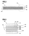
- FIG. 1 schematically illustrated, designated as a whole by 100 bipolar lead-acid battery comprises a negative end cell 102, a positive end cell 104, a bipolar cell 106 disposed between the negative end cell 102 and the positive end cell 104 and two each between the bipolar cell 106 and the negative end cell 102 and spacers (hereinafter referred to as "spacers") 108 disposed on the positive end cell 104.
- spacers spacers
- Each of the spacers 108 is substantially rectangular and frame-shaped (see 6 and 7 ) and surrounds a substantially rectangular, central passage opening 110, in which in the operating state of the bipolar lead acid battery 100 is a respective separator in the form of a (not shown in the figures) glass fiber mat is added, which is impregnated with an electrolyte, such as sulfuric acid.
- the negative end cell 102 includes an outside end plate 112 (made of aluminum, for example), a negative plate 114 and a negative grid 116 facing the spacer 108 and the bipolar cell 106.
- the positive end cell 104 includes an outer end plate 112 (made of aluminum, for example), a positive plate 118 and a positive grid 120 facing the spacer 108 and the bipolar cell 106.
- the bipolar cell 106 includes a centrally located bipolar plate 122, a positive grid 120 facing the negative end cell 102, and a negative grid 116 facing the positive end cell 104.
- each of these grids is provided with a plurality of approximately square passage openings 124 which are shown in FIG Operation of the bipolar lead-acid battery 100 are filled with a negative or a positive paste.
- the negative paste, with which the negative grid 116 is filled, contains in particular lead.
- the positive paste, with which the positive grid 120 is filled, contains in particular lead oxide.
- a negative grid 116 filled with negative paste, a spacer 108 with the separator in the form of an electrolyte-impregnated glass fiber mat and a positive grid 120 filled with positive paste together form a 2-volt electrochemical cell 126.
- bipolar lead acid battery 100 thus comprises two electrochemical 2-volt cells and thus has a nominal voltage of 4 volts.
- the bipolar lead acid battery 100 is supplemented with an additional bipolar cell 106 and an additional spacer 108 with separator between the negative end cell 102 and the positive end cell 104.
- Fig. 1 is provided to seal the electrolyte space between each spacer 108 and the respective adjacent negative grid 116 or positive grid 120 each have an annular peripheral sealing element 128.
- Each of these sealing elements 128 can be formed, for example, from a fluoroelastomer, in particular Viton.
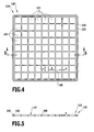
- each negative grating 116 and each positive grating 120 on its end face 130 facing the respective adjacent spacer 108 has an annular groove 132 which extends annularly around the passage openings 124 of the respective grating (see FIGS 4 and 5 ).
- Each bipolar plate 122 comprises a substrate 134, which is laminated on both sides with a metal-containing film 136 (see Fig. 11 ).
- the substrate 134 of the bipolar plate 122 can, as in Fig. 11 schematically illustrated, a centrally disposed carbon fiber nonwoven 138 and two on both sides of the carbon fiber nonwoven 138 laminated electrically conductive thermoplastic-compound films 140 include.
- the substrate 134 can also be formed from a single, electrically conductive thermoplastic-compound film 140.
- the electrically conductive thermoplastic-compound film 140 is produced as follows:
- thermoplastic material having an average particle size of, for example, about 5 ⁇ m to about 500 ⁇ m is coated with an electrically conductive filler, for example a conductive pigment in the form of carbon black, having an average primary particle size of, for example, about 1 nm about 100 nm dry mixed to obtain a thermoplastic compound.
- an electrically conductive filler for example a conductive pigment in the form of carbon black, having an average primary particle size of, for example, about 1 nm about 100 nm dry mixed to obtain a thermoplastic compound.
- the proportion of the electrically conductive filler to the thermoplastic compound is preferably about 5 percent by weight to about 30 percent by weight.
- carbon black instead of carbon black, it is also possible, for example, to use carbon semolina made from electrographite, for example carbon semolina with the designation EG 31, which is marketed by SGL Carbon AG, Wiesbaden, Germany.
- thermoplastic material used is preferably a fluorothermoplastic material.
- Suitable fluorothermoplastic materials include PFA (perfluoroalkoxy copolymer), MFA (tetrafluoroethylene-perfluoromethylvinyl ether), FEP (fluoroethylene propylene), ETFE (ethylene tetrafluoroethylene), ECTFE (ethylene-chlorotrifluoroethylene), HTE (terpolymer made from the monomers hexafluoropropylene, tetrafluoroethylene and ethylene ), THV (tetrafluoroethylene-hexafluoropropylene-vinylidene fluoride), PVDF (polyvinylidene fluoride) and / or PFV (polyvinyl fluoride).
- PFA perfluoroalkoxy copolymer
- MFA tetrafluoroethylene-perfluoromethylvinyl ether
- FEP fluoroethylene propylene
- ETFE ethylene tetrafluoroethylene
- ECTFE ethylene
- melt-processable tetrafluoroethylene copolymer may also be used as the fluorothermoplastic material; such melt-processable tetrafluoroethylene copolymers are particularly useful in the WO 00/08071 A2 and in the WO 01/60911 A1 described.
- thermoplastics for example polypropylene.
- thermoplastic material and the electrically conductive filler are fused in a hot-pressing process ("hot-compression molding” method) into a solid bond between a polymer matrix and the filler.
- thermoplastic compound produced by mixing the thermoplastic material and the electrically conductive filler by the hot pressing process a block can be made, are then prepared by peeling films of the thermoplastic compound.
- the block of the thermoplastic compound can be made in particular in the form of a hollow cylinder.
- Typical thicknesses of the films made by peeling from the block are from about 0.05 mm to about 0.5 mm.
- thermoplastic compound can also be produced by the melt extrusion process.
- thermoplastic material and an electrically conductive filler For the preparation of the mixture of a thermoplastic material and an electrically conductive filler, a powder of the thermoplastic material and a powder of the electrically conductive filler in a commercial tumble mixer are introduced and by rotating the mixing vessel over a period of at least one hour at a rotational speed in Range from about 60 rpm to about 120 rpm, wherein preferably every minute the direction of rotation is changed.
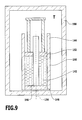
- thermoplastic compound 142 produced by this mixing of the components is converted into an in Fig. 8 shown schematically, in Inserted substantially hollow cylindrical die 144, which is closed at its lower end by an end wall 146 which carries a along the longitudinal axis of the die 144 extending central mandrel 148.
- a ram 152 is slidably guided along the longitudinal axis 154 of the die 144.
- the powdery thermoplastic compound 142 is first pre-pressed at a ram pressure P1 of at least about 30 bar for a period of at least about three minutes (see Fig. 8 ).
- the temperature T is increased to a temperature of at least about 250 ° C for a period of, for example, about two hours, preferably to a temperature above the melting temperature of the thermoplastic material contained in the thermoplastic compound, and then over a holding period of maintained for at least about another 60 hours.
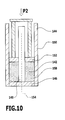
- the hot die 144 is removed from the sintering furnace 156 and again transferred to a press (see Fig. 10 ).
- the mold 144 with the polymer composition then cools within about six hours, for example, to an outside temperature of at most about 80 ° C.
- thermoplastic compound 142 melted into a composite is pushed out of the die 144, thus obtaining a hollow cylindrical shaped body 158.
- the hollow cylindrical molded body 158 is slid onto a profiled mandrel and clamped in a conventional peeling machine, as marketed for example by KELLER HCW GmbH, Ibbenbühren-Laggenbeck, Germany.
- the force transmission required for rotating the hollow-cylindrical shaped body 158 takes place by means of profiling on the mandrel surface from the rotating mandrel onto the shaped body 158.
- an electrically conductive thermoplastic compound film 140 is peeled off from the outer periphery of the molded body 158.
- the mixing of the components ETFE and carbon black takes place by turning the mixing vessel over a period of 90 minutes at a lower rotational speed of 75 rpm and an upper rotational speed of 90 rpm, with the direction of rotation being changed every minute.
- thermoplastic compound produced by this blending is filled into a die 144 having the following dimensions:
- Inner diameter of the cylindrical outer wall 150 250 mm; Outer diameter of the mandrel 148: 150 mm.
- the mold with the pre-pressed mixture of ETFE and 20 percent by weight of carbon black contained therein is transferred to a sintering furnace 156.
- the temperature T is increased to 290 ° C over a period of two hours and then maintained for a further 72 hours.
- no pressure is exerted on the polymer mass.
- the hot die 144 is removed from the sintering furnace 156 and again transferred to a press. Applying a constant pressure P2 of 65 bar then cools the mold 144 with the polymer composition within 6 hours to an outside temperature of 60 ° C to 70 ° C.
- the polymer composition is extruded from the die 144 to obtain a hollow cylindrical molded article 158.
- the hollow cylindrical shaped body 158 of ETFE and 20 percent by weight carbon black is slid onto a profiled mandrel and clamped in a peeling machine from KELLER.
- a thermoplastic compound film 140 is peeled off from the outer periphery of the hollow cylindrical molded body 158.
- the peeling speed for film production is about 11 m / min.
- the film thickness for the production of the film 140 made of ETFE and 20 weight percent carbon black is about 100 microns.
- a protective film 160 between the above-described layer structure and an upper press plate 162 and a lower press plate 164 of the heated laminate press 166 is further introduced.
- This protective film 160 may, for example, consist of a fluoropolymer material, in particular of polytetrafluoroethylene (PTFE).
- PTFE polytetrafluoroethylene
- the heated laminate press 166 is evacuated to a final pressure of, for example, at most about 10 mbar.
- a starting pressure P is applied to the layers of the bipolar plate 122 to be laminated with each other by means of the pressing plates 162 and 164.
- the temperature of the layers to be laminated (by means of a hot oil flowing through the pressure plates 162 and 164) is raised from room temperature to a temperature of, for example, at least 250 ° C.
- the starting pressure is maintained for a period of, for example, at least 5 minutes.
- the contact pressure is increased from the starting pressure to a final pressure P 'of, for example, at least 200 N / cm 2 .
- the increased pressure is maintained at the elevated temperature for a hold time of, for example, at least 5 minutes.
- the temperature is lowered to, for example, at most 100 ° C during a cooling time of, for example, about 1.5 hours while maintaining the increased contact pressure of, for example, at least 200 N / cm 2 .
- the contact pressure is lowered to zero, the laminate press 166 ventilated and taken from the carbon fiber nonwoven 138, the electrically conductive thermoplastic-compound films 140 and the metal-containing films 136 laminate taken, which Bipolar plate 122 forms.
- the protective films 160 do not bond with the metal-containing films 136 and therefore remain behind in the laminate press 166.
- the above-mentioned films have a length of, for example, about 1,200 mm and a width of, for example, about 330 mm.
- a film of PTFE with a thickness of 100 ⁇ m is inserted between these films and the press plates 162, 164 of the laminate press 166 on both sides.
- the reinforcement of the electrically conductive thermoplastic-compound foils 140 with the carbon-fiber non-woven 138 results in a further increase in the conductivity of the bipolar plate 122.
- thermoplastic compound film 140 by downwardly forming the thermoplastic compound film 140 by means of a peeling process allows the production of such highly filled thermoplastic compound films 140 that rely on the use of a carbon fiber Non-woven fabric 138 can be dispensed with to improve the electrical conductivity of the substrate 134 of the bipolar plate 122.
- thermoplastic compound foils 140 and the carbon fiber nonwoven fabric 138 of FIG Fig. 1 schematically illustrated embodiment of a substrate 134 replaced by a single electrically conductive thermoplastic-compound film 140.
- the lamination process for making the bipolar plate 122 without the carbon fiber nonwoven 138 is performed as described above in the context of a carbon fiber nonwoven substrate 134.
- the application of the Pb layer on both sides of the bipolar plate 122 is carried out by using a Pb film after the lamination process.
- the alloy of the Pb film to stabilize against oxidation contains a small amount of tin (Sn), for example, a proportion of up to a maximum of about 5 weight percent Sn.
- a negative grid 116 and a positive grid 120 are respectively formed by machining a thermoplastic compound film.
- thermoplastic compound film which need not have electrical conductivity, can be prepared in the same manner as described above for the electrically conductive thermoplastic-compound films 140 of the bipolar plate 122, but preferably with replacement of the electrically conductive filler a non-electrically conductive filler.
- thermoplastic compound films from which the grids 116 and 120 are produced in particular glass fibers, preferably short glass fibers of the E glass type, can be used.
- the negative grid 116 and the positive grid 120 may also be made by machining a film of unfilled thermoplastic material.
- the grids 116 and 120 may be made of the same thermoplastic material as the thermoplastic compound foils 140 of the bipolar plate 122; alternatively, however, other suitable materials for the grids 116 and 120 may be used.
- the grids 116 and 120 can in particular be made of a thermoplastic material, preferably polypropylene (PP) and / or polycarbonate (PC).
- PP polypropylene
- PC polycarbonate
- the mixing of the components ETFE and 20% by weight short glass fibers is carried out by rotating the mixing vessel over a period of 90 minutes at a lower rotational speed of 75 rpm and an upper rotational speed of 90 rpm, the direction of rotation being changed every minute.
- thermoplastic compound thus produced by dry blending is placed in a die 144 having the following dimensions:
- Inner diameter of the hollow cylindrical outer wall 150 250 mm
- Outer diameter of the mandrel 148 150 mm.
- the die 144 with the pre-pressed mixture of ETFE and 20 weight percent short glass fibers contained therein is transferred to a sintering furnace 156.
- the temperature is increased to 310 ° C over a period of 2.3 hours and then held for a further 24 hours.
- the hot die 144 is removed from the sintering furnace 156 and again transferred to a press.
- the polymer composition is extruded from the die 144 to obtain a hollow cylindrical molded article 158.
- the hollow cylindrical shaped body 158 made of ETFE and 20 weight percent short glass fibers is slid onto a profiled mandrel and clamped in a peeling machine of the manufacturer KELLER.
- the peeling speed for film production is 11 m / min.
- ETFE's 20% by weight short fiberglass thermoplastic non-conductive thermoplastic compound film is used for the negative grating 116 (anode) and with a thickness of 1.2 mm for the positive grating 120 (cathode).
- thermoplastic compound foils produced in the manner described above by a hot pressing method and a peeling method negative grids 116 and positive grids 120 are machined with the contours shown in FIGS 4 and 5 produced.
- the length of a grid 116 or 120 is about 360 mm and the width of a grid 116 or 120 is about 325 mm, for example.
- the substantially square passage openings 124 of the grids 116, 120 have for example a length a of approximately 28 mm and a width b of likewise approximately 28 mm.
- the width s of the webs 168 between the passage openings 124 is for example about 3 mm.
- the outboard sides of the metal-containing films 136 of the bipolar plate 122 may be before or after lamination with the gratings 116 and 120 be subjected to a surface treatment.
- it may be provided to clean and roughen the outsides of the metal-containing films 136 by "sandblasting" using glass beads, alumina or dry ice (CO 2 ).
- the negative grid 116 and the positive grid 120 may also be directly melt-deposited on the bipolar plate 122 by injection molding or by transfer molding.
- the spacers 108 of the bipolar lead-acid battery 100 can be made of a film of a thermoplastic fluoropolymer material or of polytetrafluoroethylene (PTFE) by machining with the in the 6 and 7 shown outer contour can be produced.
- PTFE polytetrafluoroethylene
- the negative plate 114 of the negative end cell 102 of the bipolar lead-acid battery 100 comprises the same substrate 134 as the bipolar plate 122, but only on one side, namely on the negative grid 116 side facing the negative plate 114, with a metal-containing foil, such as a lead / Tin foil, provided.
- the negative plate 114 may be made of the substrate and the metal-containing foil by a lamination method according to the lamination method of the bipolar plate 122.
- the positive plate 118 of the positive end cell 104 of the bipolar lead-acid battery 100 comprises the same substrate 134 as the bipolar plate 122, but is only one-sided, namely on its side facing the positive grid 120, with a metal-containing foil, for example a lead / tin foil. Mistake.
- the positive plate 118 can be fabricated from the substrate and the metal-containing film by a laminating method corresponding to the laminating method for manufacturing the bipolar plate 122.
- the negative plate 114 of the negative end cell 102 may be connected to the negative grid 116 by a laminating method corresponding to the laminating method for manufacturing the bipolar integrated cell 106.
- the positive plate 118 of the positive end cell 104 may be connected to the positive grid 120 by a laminating method corresponding to the laminating method for manufacturing the bipolar integrated cell 106.
- the positive grids 120 of the bipolar cells 106 and the positive end cell 104 are filled with positive paste.
- the negative grids 116 of the bipolar cells 106 and the negative end cell 102 are filled with negative paste.
- separators are inserted in the form of glass fiber mats.
- the glass fiber mats in the pressure-free state have a thickness which exceeds the thickness of the spacers 108, and that the glass fiber mats are compressed during assembly of the bipolar lead acid battery 100 in the longitudinal direction.
- bipolar cells 106 and spacers 108 with glass fiber mats and the negative end cell 102 and the positive end cell 104 in the in the Fig. 1 to 3 are assembled together, they are using a pressure in the Longitudinal direction 174 of the bipolar lead acid battery 100 pressed against each other and braced by suitable bracing devices in this position against each other.
- the electrolyte can be filled through the filling openings (not shown) in the spacers 108 into the glass fiber mats serving as separators.
- the bipolar lead acid battery 100 is ready for use and can be charged.
- spacers 108 and the negative gratings 116 as well as the positive gratings 120 are formed from a material containing thermoplastic material, successive spacers 108 and grids 116, 120 may be joined by welding into a cell stack in the longitudinal direction 174 of the bipolar lead acid battery 100.
- the sealing elements 128 between the spacers 108 and the same adjacent grids 116 and 120 may be omitted.
- the method described above for producing a bipolar lead acid battery 100 is particularly environmentally friendly and ensures a particularly high chemical resistance of the lead layers in the metal-containing films 136, in particular on the side of the lead layers facing the negative gratings (anode gratings) 116.
- bipolar design of the bipolar lead-acid battery 100 reduces the need for lead at the same power and thus leads to a particularly environmentally friendly end product.
Landscapes
- Chemical & Material Sciences (AREA)
- Engineering & Computer Science (AREA)
- Materials Engineering (AREA)
- Chemical Kinetics & Catalysis (AREA)
- Electrochemistry (AREA)
- General Chemical & Material Sciences (AREA)
- Composite Materials (AREA)
- Cell Separators (AREA)
- Battery Electrode And Active Subsutance (AREA)
- Fuel Cell (AREA)
- Laminated Bodies (AREA)
- Cell Electrode Carriers And Collectors (AREA)
Priority Applications (1)
| Application Number | Priority Date | Filing Date | Title |
|---|---|---|---|
| EP12163291.3A EP2487739B1 (fr) | 2008-07-29 | 2009-07-28 | Procédé de fabrication d'une plaque bipolaire et plaque bipolaire pour une batterie bipolaire |
Applications Claiming Priority (1)
| Application Number | Priority Date | Filing Date | Title |
|---|---|---|---|
| DE102008036319A DE102008036319A1 (de) | 2008-07-29 | 2008-07-29 | Verfahren zur Herstellung einer Bipolarplatte und Bipolarplatte für eine bipolare Batterie |
Related Child Applications (1)
| Application Number | Title | Priority Date | Filing Date |
|---|---|---|---|
| EP12163291.3A Division-Into EP2487739B1 (fr) | 2008-07-29 | 2009-07-28 | Procédé de fabrication d'une plaque bipolaire et plaque bipolaire pour une batterie bipolaire |
Publications (3)
| Publication Number | Publication Date |
|---|---|
| EP2157641A2 true EP2157641A2 (fr) | 2010-02-24 |
| EP2157641A3 EP2157641A3 (fr) | 2011-10-05 |
| EP2157641B1 EP2157641B1 (fr) | 2014-05-21 |
Family
ID=41264322
Family Applications (2)
| Application Number | Title | Priority Date | Filing Date |
|---|---|---|---|
| EP09166612.3A Not-in-force EP2157641B1 (fr) | 2008-07-29 | 2009-07-28 | Procédé de fabrication d'une plaque bipolaire et plaque bipolaire pour une batterie bipolaire au plomb |
| EP12163291.3A Not-in-force EP2487739B1 (fr) | 2008-07-29 | 2009-07-28 | Procédé de fabrication d'une plaque bipolaire et plaque bipolaire pour une batterie bipolaire |
Family Applications After (1)
| Application Number | Title | Priority Date | Filing Date |
|---|---|---|---|
| EP12163291.3A Not-in-force EP2487739B1 (fr) | 2008-07-29 | 2009-07-28 | Procédé de fabrication d'une plaque bipolaire et plaque bipolaire pour une batterie bipolaire |
Country Status (2)
| Country | Link |
|---|---|
| EP (2) | EP2157641B1 (fr) |
| DE (1) | DE102008036319A1 (fr) |
Cited By (3)
| Publication number | Priority date | Publication date | Assignee | Title |
|---|---|---|---|---|
| EP2613393A1 (fr) | 2012-01-04 | 2013-07-10 | Centurion Bipolair B.V. | Batterie au plomb-acide bipolaire et procédé de fabrication |
| CN113423772A (zh) * | 2019-02-13 | 2021-09-21 | 弗劳恩霍夫应用研究促进协会 | 半成品元件的亲水化方法和由此制造的电极元件、双极元件或换热器元件 |
| CN118281360A (zh) * | 2024-06-03 | 2024-07-02 | 国联汽车动力电池研究院有限责任公司 | 一种双极性全固态电池及其制备方法 |
Families Citing this family (1)
| Publication number | Priority date | Publication date | Assignee | Title |
|---|---|---|---|---|
| DE102014113803A1 (de) | 2014-09-24 | 2016-03-24 | Elringklinger Ag | Bipolarplatte, Bipolarzelle und Verfahren zu deren Herstellung |
Citations (3)
| Publication number | Priority date | Publication date | Assignee | Title |
|---|---|---|---|---|
| WO1998040920A2 (fr) | 1997-03-12 | 1998-09-17 | Nederlandse Organisatie Voor Toegepast-Natuurwetenschappelijk Onderzoek Tno | Procede pour fabriquer une plaque bipolaire |
| WO2000008071A2 (fr) | 1998-08-06 | 2000-02-17 | Omlidon Technologies Llc | (poly)tetrafluoroethylene pouvant etre traite par fusion |
| WO2001060911A1 (fr) | 2000-02-16 | 2001-08-23 | Omlidon Technologies Llc | Poly(tetrafluoroethylene) pouvant etre traite a l'etat fondu |
Family Cites Families (7)
| Publication number | Priority date | Publication date | Assignee | Title |
|---|---|---|---|---|
| US4713306A (en) * | 1986-03-24 | 1987-12-15 | Ensci, Inc. | Battery element and battery incorporating doped tin oxide coated substrate |
| US4892797A (en) * | 1989-03-10 | 1990-01-09 | Alupower, Inc. | Bipolar electrode and process for manufacturing same |
| US5264305A (en) * | 1991-05-03 | 1993-11-23 | Energy Research Corporation | Zinc secondary battery having bipolar plate construction with horizontally disposed battery components |
| US5348817A (en) * | 1993-06-02 | 1994-09-20 | Gnb Battery Technologies Inc. | Bipolar lead-acid battery |
| US5393617A (en) * | 1993-10-08 | 1995-02-28 | Electro Energy, Inc. | Bipolar electrochmeical battery of stacked wafer cells |
| US5800946A (en) * | 1996-12-06 | 1998-09-01 | Grosvenor; Victor L. | Bipolar lead-acid battery plates |
| DE10117985A1 (de) * | 2001-04-10 | 2002-10-24 | Rennebeck Klaus | Brennstoff-Aufoxidations-Verfahren und Elektrolyse, mit Feststoffelektrolyten-Composit, in archimedischen Rollwickelspiralen mit spongiösen, offenzelligen Koaxial-Gasdiffusionselektroden-Rohr-Profilen |
-
2008
- 2008-07-29 DE DE102008036319A patent/DE102008036319A1/de not_active Withdrawn
-
2009
- 2009-07-28 EP EP09166612.3A patent/EP2157641B1/fr not_active Not-in-force
- 2009-07-28 EP EP12163291.3A patent/EP2487739B1/fr not_active Not-in-force
Patent Citations (3)
| Publication number | Priority date | Publication date | Assignee | Title |
|---|---|---|---|---|
| WO1998040920A2 (fr) | 1997-03-12 | 1998-09-17 | Nederlandse Organisatie Voor Toegepast-Natuurwetenschappelijk Onderzoek Tno | Procede pour fabriquer une plaque bipolaire |
| WO2000008071A2 (fr) | 1998-08-06 | 2000-02-17 | Omlidon Technologies Llc | (poly)tetrafluoroethylene pouvant etre traite par fusion |
| WO2001060911A1 (fr) | 2000-02-16 | 2001-08-23 | Omlidon Technologies Llc | Poly(tetrafluoroethylene) pouvant etre traite a l'etat fondu |
Cited By (4)
| Publication number | Priority date | Publication date | Assignee | Title |
|---|---|---|---|---|
| EP2613393A1 (fr) | 2012-01-04 | 2013-07-10 | Centurion Bipolair B.V. | Batterie au plomb-acide bipolaire et procédé de fabrication |
| CN113423772A (zh) * | 2019-02-13 | 2021-09-21 | 弗劳恩霍夫应用研究促进协会 | 半成品元件的亲水化方法和由此制造的电极元件、双极元件或换热器元件 |
| CN118281360A (zh) * | 2024-06-03 | 2024-07-02 | 国联汽车动力电池研究院有限责任公司 | 一种双极性全固态电池及其制备方法 |
| CN118281360B (zh) * | 2024-06-03 | 2024-10-01 | 国联汽车动力电池研究院有限责任公司 | 一种双极性全固态电池及其制备方法 |
Also Published As
| Publication number | Publication date |
|---|---|
| EP2157641A3 (fr) | 2011-10-05 |
| EP2487739B1 (fr) | 2014-01-08 |
| EP2487739A1 (fr) | 2012-08-15 |
| EP2157641B1 (fr) | 2014-05-21 |
| DE102008036319A1 (de) | 2010-02-04 |
Similar Documents
| Publication | Publication Date | Title |
|---|---|---|
| DE602005002916T2 (de) | Separator zur Verwendung in einer Lithiumionensekundärbatterie | |
| DE69716483T2 (de) | Verfahren zur herstellung einer bipolaren platte | |
| EP1359633B1 (fr) | Elément galvanique avec des électrodes minces | |
| DE112008002146B4 (de) | Zelle für Brennstoffzelle, und Brennstoffzelle | |
| DE112014006933B4 (de) | Verfahren zum Herstellen einer Beschichtung aus Kohlenstoffpartikeln oder Metalloxidpartikeln mit Submikrongröße auf den Oberflächen von Partikeln aus einem aktiven Elektrodenmaterial für eine Lithium-Sekundärbatterie | |
| DE102021130262A1 (de) | Verfahren zur Herstellung von lösungsmittelfreien mehrschichtigen Elektroden | |
| EP0154772B1 (fr) | Plaque bipolaire pour appareil comprenant un empilement de cellules électrochimiques à électrolyte solide, et son procédé de fabrication | |
| DE102022109368A1 (de) | Elektrodenbeschichtung unter verwendung eines porösen stromkollektors | |
| EP2157641B1 (fr) | Procédé de fabrication d'une plaque bipolaire et plaque bipolaire pour une batterie bipolaire au plomb | |
| DE102016217369A1 (de) | Elektrode mit erhöhtem Aktivmaterialanteil | |
| DE102016217383A1 (de) | Verfahren zur Herstellung von Elektroden mit verbesserter Stromsammlerstruktur | |
| EP2157642A2 (fr) | Procédé de fabrication d'une cellule bipolaire et cellule bipolaire pour une batterie bipolaire | |
| EP1302993A2 (fr) | Procédé de fabrication d'une unité électrodes-séparateurs pour éléments galvaniques | |
| DE19836651A1 (de) | Mehrschichtige Elektrode für elektrochemische Anwendungen | |
| WO2019145337A1 (fr) | Procédé de fabrication d'une électrode pour une batterie et électrode pour une batterie | |
| DE102008036320B4 (de) | Verfahren zur Herstellung einer Bipolarplatte und Bipolarplatte für eine bipolare Batterie | |
| KR101279174B1 (ko) | 2차 전지의 전극 구조 및 그 제조 방법 | |
| DE102022116107A1 (de) | Festkörperelektrode mit integriertem sulfidseparator | |
| DE102023131567B3 (de) | System zum herstellen von elektroden mit verbesserter kantenqualität und verfahren | |
| EP3614476A1 (fr) | Accumulateur lithium-ion à structure en sandwich et son procédé de fabrication | |
| EP1261046B1 (fr) | Méthode de fabrication d'un assemblage électrode/séparateur pour éléments galvaniques | |
| DE102017209960A1 (de) | Verfahren zum Herstellen einer Elektrode, insbesondere für eine Batterie | |
| DE102016215666A1 (de) | Elektrodenanordnung für Lithium-basierte galvanische Zellen und Verfahren zu deren Herstellung | |
| DE102009037144B4 (de) | Kontaktelement zum elektrischen Kontaktieren einer stromerzeugenden elektrochemischen Zelle sowie Herstellungsverfahren für selbiges | |
| DE102014226806B3 (de) | Verfahren zur Herstellung elektrisch leitender Verbindungen, von mindestens zwei stoffschlüssig miteinander verbundenen Fügepartnern |
Legal Events
| Date | Code | Title | Description |
|---|---|---|---|
| PUAI | Public reference made under article 153(3) epc to a published international application that has entered the european phase |
Free format text: ORIGINAL CODE: 0009012 |
|
| AK | Designated contracting states |
Kind code of ref document: A2 Designated state(s): AT BE BG CH CY CZ DE DK EE ES FI FR GB GR HR HU IE IS IT LI LT LU LV MC MK MT NL NO PL PT RO SE SI SK SM TR |
|
| REG | Reference to a national code |
Ref country code: DE Ref legal event code: R079 Ref document number: 502009009420 Country of ref document: DE Free format text: PREVIOUS MAIN CLASS: H01M0004680000 Ipc: H01M0004660000 |
|
| PUAL | Search report despatched |
Free format text: ORIGINAL CODE: 0009013 |
|
| AK | Designated contracting states |
Kind code of ref document: A3 Designated state(s): AT BE BG CH CY CZ DE DK EE ES FI FR GB GR HR HU IE IS IT LI LT LU LV MC MK MT NL NO PL PT RO SE SI SK SM TR |
|
| RIC1 | Information provided on ipc code assigned before grant |
Ipc: H01M 4/68 20060101ALI20110829BHEP Ipc: H01M 4/66 20060101AFI20110829BHEP |
|
| 17P | Request for examination filed |
Effective date: 20120405 |
|
| 17Q | First examination report despatched |
Effective date: 20121029 |
|
| GRAP | Despatch of communication of intention to grant a patent |
Free format text: ORIGINAL CODE: EPIDOSNIGR1 |
|
| INTG | Intention to grant announced |
Effective date: 20140108 |
|
| GRAS | Grant fee paid |
Free format text: ORIGINAL CODE: EPIDOSNIGR3 |
|
| GRAA | (expected) grant |
Free format text: ORIGINAL CODE: 0009210 |
|
| AK | Designated contracting states |
Kind code of ref document: B1 Designated state(s): AT BE BG CH CY CZ DE DK EE ES FI FR GB GR HR HU IE IS IT LI LT LU LV MC MK MT NL NO PL PT RO SE SI SK SM TR |
|
| REG | Reference to a national code |
Ref country code: GB Ref legal event code: FG4D Free format text: NOT ENGLISH |
|
| REG | Reference to a national code |
Ref country code: CH Ref legal event code: EP |
|
| REG | Reference to a national code |
Ref country code: AT Ref legal event code: REF Ref document number: 670001 Country of ref document: AT Kind code of ref document: T Effective date: 20140615 |
|
| REG | Reference to a national code |
Ref country code: IE Ref legal event code: FG4D Free format text: LANGUAGE OF EP DOCUMENT: GERMAN |
|
| REG | Reference to a national code |
Ref country code: DE Ref legal event code: R096 Ref document number: 502009009420 Country of ref document: DE Effective date: 20140703 |
|
| REG | Reference to a national code |
Ref country code: NL Ref legal event code: VDEP Effective date: 20140521 |
|
| REG | Reference to a national code |
Ref country code: LT Ref legal event code: MG4D |
|
| PG25 | Lapsed in a contracting state [announced via postgrant information from national office to epo] |
Ref country code: IS Free format text: LAPSE BECAUSE OF FAILURE TO SUBMIT A TRANSLATION OF THE DESCRIPTION OR TO PAY THE FEE WITHIN THE PRESCRIBED TIME-LIMIT Effective date: 20140921 Ref country code: LT Free format text: LAPSE BECAUSE OF FAILURE TO SUBMIT A TRANSLATION OF THE DESCRIPTION OR TO PAY THE FEE WITHIN THE PRESCRIBED TIME-LIMIT Effective date: 20140521 Ref country code: FI Free format text: LAPSE BECAUSE OF FAILURE TO SUBMIT A TRANSLATION OF THE DESCRIPTION OR TO PAY THE FEE WITHIN THE PRESCRIBED TIME-LIMIT Effective date: 20140521 Ref country code: GR Free format text: LAPSE BECAUSE OF FAILURE TO SUBMIT A TRANSLATION OF THE DESCRIPTION OR TO PAY THE FEE WITHIN THE PRESCRIBED TIME-LIMIT Effective date: 20140822 Ref country code: NO Free format text: LAPSE BECAUSE OF FAILURE TO SUBMIT A TRANSLATION OF THE DESCRIPTION OR TO PAY THE FEE WITHIN THE PRESCRIBED TIME-LIMIT Effective date: 20140821 |
|
| PG25 | Lapsed in a contracting state [announced via postgrant information from national office to epo] |
Ref country code: HR Free format text: LAPSE BECAUSE OF FAILURE TO SUBMIT A TRANSLATION OF THE DESCRIPTION OR TO PAY THE FEE WITHIN THE PRESCRIBED TIME-LIMIT Effective date: 20140521 Ref country code: PL Free format text: LAPSE BECAUSE OF FAILURE TO SUBMIT A TRANSLATION OF THE DESCRIPTION OR TO PAY THE FEE WITHIN THE PRESCRIBED TIME-LIMIT Effective date: 20140521 Ref country code: SE Free format text: LAPSE BECAUSE OF FAILURE TO SUBMIT A TRANSLATION OF THE DESCRIPTION OR TO PAY THE FEE WITHIN THE PRESCRIBED TIME-LIMIT Effective date: 20140521 Ref country code: ES Free format text: LAPSE BECAUSE OF FAILURE TO SUBMIT A TRANSLATION OF THE DESCRIPTION OR TO PAY THE FEE WITHIN THE PRESCRIBED TIME-LIMIT Effective date: 20140521 Ref country code: LV Free format text: LAPSE BECAUSE OF FAILURE TO SUBMIT A TRANSLATION OF THE DESCRIPTION OR TO PAY THE FEE WITHIN THE PRESCRIBED TIME-LIMIT Effective date: 20140521 |
|
| PG25 | Lapsed in a contracting state [announced via postgrant information from national office to epo] |
Ref country code: PT Free format text: LAPSE BECAUSE OF FAILURE TO SUBMIT A TRANSLATION OF THE DESCRIPTION OR TO PAY THE FEE WITHIN THE PRESCRIBED TIME-LIMIT Effective date: 20140922 |
|
| PG25 | Lapsed in a contracting state [announced via postgrant information from national office to epo] |
Ref country code: EE Free format text: LAPSE BECAUSE OF FAILURE TO SUBMIT A TRANSLATION OF THE DESCRIPTION OR TO PAY THE FEE WITHIN THE PRESCRIBED TIME-LIMIT Effective date: 20140521 Ref country code: SK Free format text: LAPSE BECAUSE OF FAILURE TO SUBMIT A TRANSLATION OF THE DESCRIPTION OR TO PAY THE FEE WITHIN THE PRESCRIBED TIME-LIMIT Effective date: 20140521 Ref country code: DK Free format text: LAPSE BECAUSE OF FAILURE TO SUBMIT A TRANSLATION OF THE DESCRIPTION OR TO PAY THE FEE WITHIN THE PRESCRIBED TIME-LIMIT Effective date: 20140521 Ref country code: CZ Free format text: LAPSE BECAUSE OF FAILURE TO SUBMIT A TRANSLATION OF THE DESCRIPTION OR TO PAY THE FEE WITHIN THE PRESCRIBED TIME-LIMIT Effective date: 20140521 Ref country code: RO Free format text: LAPSE BECAUSE OF FAILURE TO SUBMIT A TRANSLATION OF THE DESCRIPTION OR TO PAY THE FEE WITHIN THE PRESCRIBED TIME-LIMIT Effective date: 20140521 |
|
| REG | Reference to a national code |
Ref country code: DE Ref legal event code: R097 Ref document number: 502009009420 Country of ref document: DE |
|
| PG25 | Lapsed in a contracting state [announced via postgrant information from national office to epo] |
Ref country code: NL Free format text: LAPSE BECAUSE OF FAILURE TO SUBMIT A TRANSLATION OF THE DESCRIPTION OR TO PAY THE FEE WITHIN THE PRESCRIBED TIME-LIMIT Effective date: 20140521 Ref country code: LU Free format text: LAPSE BECAUSE OF FAILURE TO SUBMIT A TRANSLATION OF THE DESCRIPTION OR TO PAY THE FEE WITHIN THE PRESCRIBED TIME-LIMIT Effective date: 20140728 |
|
| REG | Reference to a national code |
Ref country code: CH Ref legal event code: PL |
|
| PLBE | No opposition filed within time limit |
Free format text: ORIGINAL CODE: 0009261 |
|
| STAA | Information on the status of an ep patent application or granted ep patent |
Free format text: STATUS: NO OPPOSITION FILED WITHIN TIME LIMIT |
|
| REG | Reference to a national code |
Ref country code: IE Ref legal event code: MM4A |
|
| 26N | No opposition filed |
Effective date: 20150224 |
|
| GBPC | Gb: european patent ceased through non-payment of renewal fee |
Effective date: 20140821 |
|
| PG25 | Lapsed in a contracting state [announced via postgrant information from national office to epo] |
Ref country code: IT Free format text: LAPSE BECAUSE OF FAILURE TO SUBMIT A TRANSLATION OF THE DESCRIPTION OR TO PAY THE FEE WITHIN THE PRESCRIBED TIME-LIMIT Effective date: 20140521 Ref country code: LI Free format text: LAPSE BECAUSE OF NON-PAYMENT OF DUE FEES Effective date: 20140731 Ref country code: CH Free format text: LAPSE BECAUSE OF NON-PAYMENT OF DUE FEES Effective date: 20140731 |
|
| REG | Reference to a national code |
Ref country code: DE Ref legal event code: R097 Ref document number: 502009009420 Country of ref document: DE Effective date: 20150224 |
|
| REG | Reference to a national code |
Ref country code: DE Ref legal event code: R082 Ref document number: 502009009420 Country of ref document: DE Representative=s name: HOEGER, STELLRECHT & PARTNER PATENTANWAELTE MB, DE |
|
| PG25 | Lapsed in a contracting state [announced via postgrant information from national office to epo] |
Ref country code: SI Free format text: LAPSE BECAUSE OF FAILURE TO SUBMIT A TRANSLATION OF THE DESCRIPTION OR TO PAY THE FEE WITHIN THE PRESCRIBED TIME-LIMIT Effective date: 20140521 Ref country code: GB Free format text: LAPSE BECAUSE OF NON-PAYMENT OF DUE FEES Effective date: 20140821 |
|
| PG25 | Lapsed in a contracting state [announced via postgrant information from national office to epo] |
Ref country code: IE Free format text: LAPSE BECAUSE OF NON-PAYMENT OF DUE FEES Effective date: 20140728 |
|
| REG | Reference to a national code |
Ref country code: AT Ref legal event code: MM01 Ref document number: 670001 Country of ref document: AT Kind code of ref document: T Effective date: 20140728 |
|
| PG25 | Lapsed in a contracting state [announced via postgrant information from national office to epo] |
Ref country code: AT Free format text: LAPSE BECAUSE OF NON-PAYMENT OF DUE FEES Effective date: 20140728 |
|
| PG25 | Lapsed in a contracting state [announced via postgrant information from national office to epo] |
Ref country code: MC Free format text: LAPSE BECAUSE OF FAILURE TO SUBMIT A TRANSLATION OF THE DESCRIPTION OR TO PAY THE FEE WITHIN THE PRESCRIBED TIME-LIMIT Effective date: 20140521 Ref country code: SM Free format text: LAPSE BECAUSE OF FAILURE TO SUBMIT A TRANSLATION OF THE DESCRIPTION OR TO PAY THE FEE WITHIN THE PRESCRIBED TIME-LIMIT Effective date: 20140521 |
|
| PG25 | Lapsed in a contracting state [announced via postgrant information from national office to epo] |
Ref country code: CY Free format text: LAPSE BECAUSE OF FAILURE TO SUBMIT A TRANSLATION OF THE DESCRIPTION OR TO PAY THE FEE WITHIN THE PRESCRIBED TIME-LIMIT Effective date: 20140521 Ref country code: MT Free format text: LAPSE BECAUSE OF FAILURE TO SUBMIT A TRANSLATION OF THE DESCRIPTION OR TO PAY THE FEE WITHIN THE PRESCRIBED TIME-LIMIT Effective date: 20140521 Ref country code: BG Free format text: LAPSE BECAUSE OF FAILURE TO SUBMIT A TRANSLATION OF THE DESCRIPTION OR TO PAY THE FEE WITHIN THE PRESCRIBED TIME-LIMIT Effective date: 20140521 |
|
| REG | Reference to a national code |
Ref country code: FR Ref legal event code: PLFP Year of fee payment: 8 |
|
| PG25 | Lapsed in a contracting state [announced via postgrant information from national office to epo] |
Ref country code: BE Free format text: LAPSE BECAUSE OF FAILURE TO SUBMIT A TRANSLATION OF THE DESCRIPTION OR TO PAY THE FEE WITHIN THE PRESCRIBED TIME-LIMIT Effective date: 20140731 Ref country code: HU Free format text: LAPSE BECAUSE OF FAILURE TO SUBMIT A TRANSLATION OF THE DESCRIPTION OR TO PAY THE FEE WITHIN THE PRESCRIBED TIME-LIMIT; INVALID AB INITIO Effective date: 20090728 Ref country code: TR Free format text: LAPSE BECAUSE OF FAILURE TO SUBMIT A TRANSLATION OF THE DESCRIPTION OR TO PAY THE FEE WITHIN THE PRESCRIBED TIME-LIMIT Effective date: 20140521 |
|
| REG | Reference to a national code |
Ref country code: FR Ref legal event code: PLFP Year of fee payment: 9 |
|
| PG25 | Lapsed in a contracting state [announced via postgrant information from national office to epo] |
Ref country code: MK Free format text: LAPSE BECAUSE OF FAILURE TO SUBMIT A TRANSLATION OF THE DESCRIPTION OR TO PAY THE FEE WITHIN THE PRESCRIBED TIME-LIMIT Effective date: 20140521 |
|
| REG | Reference to a national code |
Ref country code: FR Ref legal event code: PLFP Year of fee payment: 10 |
|
| PGFP | Annual fee paid to national office [announced via postgrant information from national office to epo] |
Ref country code: DE Payment date: 20180725 Year of fee payment: 10 Ref country code: FR Payment date: 20180723 Year of fee payment: 10 |
|
| REG | Reference to a national code |
Ref country code: DE Ref legal event code: R082 Ref document number: 502009009420 Country of ref document: DE Representative=s name: HOEGER, STELLRECHT & PARTNER PATENTANWAELTE MB, DE |
|
| REG | Reference to a national code |
Ref country code: DE Ref legal event code: R119 Ref document number: 502009009420 Country of ref document: DE |
|
| PG25 | Lapsed in a contracting state [announced via postgrant information from national office to epo] |
Ref country code: DE Free format text: LAPSE BECAUSE OF NON-PAYMENT OF DUE FEES Effective date: 20200201 |
|
| PG25 | Lapsed in a contracting state [announced via postgrant information from national office to epo] |
Ref country code: FR Free format text: LAPSE BECAUSE OF NON-PAYMENT OF DUE FEES Effective date: 20190731 |