EP2157675A2 - Disjoncteur et utilisation d'un tel disjoncteur dans un appareil électrique - Google Patents
Disjoncteur et utilisation d'un tel disjoncteur dans un appareil électrique Download PDFInfo
- Publication number
- EP2157675A2 EP2157675A2 EP09010768A EP09010768A EP2157675A2 EP 2157675 A2 EP2157675 A2 EP 2157675A2 EP 09010768 A EP09010768 A EP 09010768A EP 09010768 A EP09010768 A EP 09010768A EP 2157675 A2 EP2157675 A2 EP 2157675A2
- Authority
- EP
- European Patent Office
- Prior art keywords
- circuit breaker
- voltage
- protective conductor
- conductor
- evaluation
- Prior art date
- Legal status (The legal status is an assumption and is not a legal conclusion. Google has not performed a legal analysis and makes no representation as to the accuracy of the status listed.)
- Withdrawn
Links
- 239000004020 conductor Substances 0.000 claims abstract description 34
- 238000011156 evaluation Methods 0.000 claims abstract description 17
- 230000007935 neutral effect Effects 0.000 claims abstract description 9
- 230000001681 protective effect Effects 0.000 claims description 17
- 238000001514 detection method Methods 0.000 claims description 11
- 230000008054 signal transmission Effects 0.000 claims description 2
- 230000001960 triggered effect Effects 0.000 claims description 2
- 238000010586 diagram Methods 0.000 description 11
- 230000006870 function Effects 0.000 description 8
- 238000009413 insulation Methods 0.000 description 5
- 230000008878 coupling Effects 0.000 description 4
- 238000010168 coupling process Methods 0.000 description 4
- 238000005859 coupling reaction Methods 0.000 description 4
- 230000007613 environmental effect Effects 0.000 description 4
- 230000003287 optical effect Effects 0.000 description 4
- 238000010276 construction Methods 0.000 description 3
- 238000012795 verification Methods 0.000 description 3
- 230000035945 sensitivity Effects 0.000 description 2
- 230000005672 electromagnetic field Effects 0.000 description 1
- 238000002955 isolation Methods 0.000 description 1
- 230000009993 protective function Effects 0.000 description 1
Images


Classifications
-
- H—ELECTRICITY
- H02—GENERATION; CONVERSION OR DISTRIBUTION OF ELECTRIC POWER
- H02H—EMERGENCY PROTECTIVE CIRCUIT ARRANGEMENTS
- H02H1/00—Details of emergency protective circuit arrangements
- H02H1/0007—Details of emergency protective circuit arrangements concerning the detecting means
-
- H—ELECTRICITY
- H02—GENERATION; CONVERSION OR DISTRIBUTION OF ELECTRIC POWER
- H02H—EMERGENCY PROTECTIVE CIRCUIT ARRANGEMENTS
- H02H3/00—Emergency protective circuit arrangements for automatic disconnection directly responsive to an undesired change from normal electric working condition with or without subsequent reconnection ; integrated protection
- H02H3/26—Emergency protective circuit arrangements for automatic disconnection directly responsive to an undesired change from normal electric working condition with or without subsequent reconnection ; integrated protection responsive to difference between voltages or between currents; responsive to phase angle between voltages or between currents
- H02H3/32—Emergency protective circuit arrangements for automatic disconnection directly responsive to an undesired change from normal electric working condition with or without subsequent reconnection ; integrated protection responsive to difference between voltages or between currents; responsive to phase angle between voltages or between currents involving comparison of the voltage or current values at corresponding points in different conductors of a single system, e.g. of currents in go and return conductors
- H02H3/33—Emergency protective circuit arrangements for automatic disconnection directly responsive to an undesired change from normal electric working condition with or without subsequent reconnection ; integrated protection responsive to difference between voltages or between currents; responsive to phase angle between voltages or between currents involving comparison of the voltage or current values at corresponding points in different conductors of a single system, e.g. of currents in go and return conductors using summation current transformers
- H02H3/338—Emergency protective circuit arrangements for automatic disconnection directly responsive to an undesired change from normal electric working condition with or without subsequent reconnection ; integrated protection responsive to difference between voltages or between currents; responsive to phase angle between voltages or between currents involving comparison of the voltage or current values at corresponding points in different conductors of a single system, e.g. of currents in go and return conductors using summation current transformers also responsive to wiring error, e.g. loss of neutral, break
Definitions
- the invention relates to a circuit breaker and the use of such a circuit breaker in an electrical device according to claims 1 and 3.
- DI circuit breakers are known. In these, a fault current is detected when the sum of the currents of one (or more phase conductors) and a neutral are not equal to "0". In the case of a DI circuit breaker, an all-pole disconnection takes place in which the protective conductor is also disconnected. This is intended to prevent a hazard to persons that could occur due to leakage currents flowing through the protective conductor.
- An embodiment of a DI circuit breaker is from the EP 806 825 B1 known. There, a sensor surface is attached to a housing of an electrical device. When a person touches this sensor surface, this sensor surface is connected to the ground via the impedance of this person. If there is an insulation fault and thus a voltage on the protective conductor, this leads to a current flow. This current flow is evaluated to determine if tripping is required.
- the detection means for the insulation fault on the protective conductor to an antenna device which is connected via an evaluation circuit to the protective conductor, wherein the antenna device signals of electromagnetic frequencies of a ripple voltage are received, wherein the voltage signals of the received voltage with the voltage level on be compared to the protective conductor, wherein in the event of a detected phase voltage on the protective conductor, the tripping means of the DI residual current circuit breaker are triggered.
- the signal transmissions between the detection means and the triggering means take place optically.
- Claim 3 relates to the use of a DI residual current circuit breaker according to claim 1 or 2 in an electrical device.
- the electrical device may advantageously be a device that operates under different environmental conditions.
- these environmental conditions are very different, ranging from dry interiors of buildings to outdoor use and on construction sites, it proves to be advantageous in the present invention that the verification is independent of these environmental conditions.
- Such devices may be, for example, hand tools in the construction sector such as drills, rotary hammers, circular saws, jigsaws, electric grinders or the like.
- the present invention can also find use in devices that are typically operated under always similar operating conditions.
- FIG. 1 shows a circuit diagram with function blocks for a circuit breaker according to the present invention.
- a phase conductor 1 and a neutral conductor 2 to see.
- a protective conductor 3 is present.
- the reference numeral 4 designates the function block, which represents the generation of an auxiliary voltage for the switching stage 8.
- the ripple voltage detector 6 is connected to the verification of a fault condition with the protective conductor 3.
- the braking voltage detector 6 is optically coupled to an evaluation circuit 7, by means of which it is detected whether the protective conductor 3 has an overvoltage or an undervoltage.
- This evaluation circuit 7 is in turn optically connected to an input of the switching stage 8.
- the evaluation circuit 7 and the ripple voltage detector 6 is still provided via a voltage divider 14 from the phase conductor 1 and the neutral conductor 2, a voltage available.
- controllable switches 9, 10, 11 and 12 are controlled, which are opened in the event of a fault.
- a control means 13 is still controlled via the switching stage 8, by means of which a Radioabschaltsperre the evaluation circuit 7 takes place when an error condition has been detected.
- DI trip level 15 To check a fault current between the phase conductor 1 and the neutral conductor 2 is still a known DI trip level 15 is present. Via setting means 16 it can be preset whether the sensitivity for the detection of the fault current should be 10 mA or 30 mA. From the DI trigger element can still be displayed (for example, in color), how large the measured fault current was. The output signal of the DI trip stage 15 is supplied to a further input of the switching stage 8. This triggers when at least one of the circuits 7 or 15 has detected an error.
- a button 17 is still available, by means of the actuation of which in a known manner a fault current can be induced, so that the triggering of the circuit breaker can be checked.
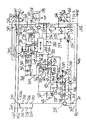
- FIG. 2 shows a wiring diagram to the in FIG. 1 explained function blocks in detail.
- This circuit diagram also contains the ripple voltage detector 6.
- FIG. 2 there is an optical coupling between the ripple voltage detector 6 and the components of FIG. 2 that form the evaluation circuit 7.
- One end of the auxiliary voltage generation is connected to the PE corresponding to the reference numeral 3.
- the lines with the reference numerals 203 and 204 show the optical coupling between the evaluation circuit 7 and the components of the switching stage 8.
- FIG. 3 shows a circuit diagram with function blocks for a circuit breaker according to the present invention.
- a phase conductor 301 and a neutral 302 can be seen.
- a protective conductor 303 is present.
- the reference numerals 304 and 305 designate the functional blocks representing the generation of an auxiliary voltage for the ripple voltage detector 306.
- the Ripple voltage detector 306 is connected to the protective conductor 303 for checking a fault condition.
- the ripple voltage detector 306 is optically coupled to an evaluation circuit 307, by means of which it is detected whether the protective conductor has an overvoltage or an undervoltage.
- This evaluation circuit 307 is in turn optically connected to an input of a switching stage 408.
- the evaluation circuit 307 is still provided via a voltage divider 314 from the phase conductor 301 and the neutral conductor 302, a voltage available.
- controllable switches 309, 310, 311 and 312 are controlled, which are opened in the event of a fault.
- a control means 313 is still controlled via the switching stage 308, by means of which a Radioabschaltsperre the evaluation circuit 307 takes place when an error condition has been detected.
- DI trip stage 315 To check a fault current between the phase conductor 301 and the neutral conductor 302 is still a known DI trip stage 315 available. Via setting means 316 it can be preset whether the sensitivity for the detection of the fault current should be 10 mA or 30 mA. From the DI trigger element can still be displayed (for example, in color), how large the measured fault current was. The output of the DI trip stage 315 is applied to another input of the switching circuit 308. This triggers when at least one of the circuits 307 or 315 has detected an error.
- a button 317 is still available, by means of the actuation of which in a known manner a fault current can be induced, so that the triggering of the circuit breaker can be checked.
- FIG. 4 shows a circuit diagram of a part of in FIG. 3 explained functional blocks in detail. This circuit corresponds to the ripple voltage detector used in FIG. 5 is shown in detail.
- the reference numeral 401 there is an optical coupling to the location indicated by reference numeral 501 of FIG FIG. 5
- FIG. 4 there is an optical coupling to the designated by the reference numeral 502 position of FIG. 5
- Those with the reference numeral 403 marked position of FIG. 4 is contacted via a PIN with the location in the FIG. 5 designated by the reference numeral 503.
- FIG. 5 shows again a detailed diagram of the ripple voltage detector 6.
- the connections to the circuit after FIG. 4 are already related to FIG. 4 explained.
Landscapes
- Breakers (AREA)
- Emergency Protection Circuit Devices (AREA)
- Driving Mechanisms And Operating Circuits Of Arc-Extinguishing High-Tension Switches (AREA)
Applications Claiming Priority (1)
| Application Number | Priority Date | Filing Date | Title |
|---|---|---|---|
| DE200810039249 DE102008039249A1 (de) | 2008-08-22 | 2008-08-22 | Schutzschalter und Verwendung eines derartigen Schutzschalters in einem elektrischen Gerät |
Publications (2)
| Publication Number | Publication Date |
|---|---|
| EP2157675A2 true EP2157675A2 (fr) | 2010-02-24 |
| EP2157675A3 EP2157675A3 (fr) | 2012-04-25 |
Family
ID=41479331
Family Applications (1)
| Application Number | Title | Priority Date | Filing Date |
|---|---|---|---|
| EP09010768A Withdrawn EP2157675A3 (fr) | 2008-08-22 | 2009-08-21 | Disjoncteur et utilisation d'un tel disjoncteur dans un appareil électrique |
Country Status (2)
| Country | Link |
|---|---|
| EP (1) | EP2157675A3 (fr) |
| DE (1) | DE102008039249A1 (fr) |
Cited By (1)
| Publication number | Priority date | Publication date | Assignee | Title |
|---|---|---|---|---|
| CN104521088A (zh) * | 2012-07-05 | 2015-04-15 | 黑格电子股份有限公司 | 差动保护设备 |
Citations (2)
| Publication number | Priority date | Publication date | Assignee | Title |
|---|---|---|---|---|
| EP0848471A2 (fr) | 1996-12-12 | 1998-06-17 | Heinrich Kopp Ag | Dispositif de protection contre les courants de défaut |
| EP0806825B1 (fr) | 1996-05-07 | 2003-07-09 | Heinrich Kopp Ag | Système de protection différentielle |
-
2008
- 2008-08-22 DE DE200810039249 patent/DE102008039249A1/de not_active Ceased
-
2009
- 2009-08-21 EP EP09010768A patent/EP2157675A3/fr not_active Withdrawn
Patent Citations (2)
| Publication number | Priority date | Publication date | Assignee | Title |
|---|---|---|---|---|
| EP0806825B1 (fr) | 1996-05-07 | 2003-07-09 | Heinrich Kopp Ag | Système de protection différentielle |
| EP0848471A2 (fr) | 1996-12-12 | 1998-06-17 | Heinrich Kopp Ag | Dispositif de protection contre les courants de défaut |
Cited By (2)
| Publication number | Priority date | Publication date | Assignee | Title |
|---|---|---|---|---|
| CN104521088A (zh) * | 2012-07-05 | 2015-04-15 | 黑格电子股份有限公司 | 差动保护设备 |
| CN104521088B (zh) * | 2012-07-05 | 2017-05-31 | 黑格电子股份有限公司 | 差动保护设备 |
Also Published As
| Publication number | Publication date |
|---|---|
| EP2157675A3 (fr) | 2012-04-25 |
| DE102008039249A1 (de) | 2010-02-25 |
Similar Documents
| Publication | Publication Date | Title |
|---|---|---|
| DE102015207456B3 (de) | Isolationsüberwachungsgerät mit Spannungsüberwachung und zugrunde liegendes Verfahren | |
| EP2020014B1 (fr) | Dispositif de commutation | |
| DE112013002126T5 (de) | Umschlossene elektrische Zähl- und Schutzvorrichtung einschließlich eines externen Trennschalthebels | |
| DE102009040692B4 (de) | Leistungsschalter | |
| EP4377986A1 (fr) | Disjoncteur | |
| DE102016105882A1 (de) | Verfahren und Vorrichtung zur Schutzleiterüberwachung | |
| EP0184983A1 (fr) | Dispositif auxiliaire pour le forage de béton armé | |
| DE102012204964A1 (de) | Schutzschaltgerät und Schutzschaltgerätanordnung | |
| DE102015207444A1 (de) | Brandschutzschalter | |
| DE102021133662A1 (de) | Verfahren zur Erkennung von Fehlerzuständen eines Schutzleiters | |
| DE102014114994A1 (de) | Stromverteilersysteme und Verfahren zum Prüfen eines Stromverteilersystems | |
| EP2243147B1 (fr) | Commutateur de protection contre les courants de défaut | |
| DE102019214821B4 (de) | Leistungsschalter und mobiles Gerät | |
| EP2157675A2 (fr) | Disjoncteur et utilisation d'un tel disjoncteur dans un appareil électrique | |
| WO2008034400A1 (fr) | Procédé pour générer un signal d'erreur indiquant la présence d'une erreur dans un circuit électrique de transformateur de courant auxiliaire, ainsi que dispositif de protection par circuit de compensation | |
| DE102013017252A1 (de) | Überwachungselektronik - Kabeltrommel Schutzleiterüberwachung u. Stromverteiler-Modul | |
| DE102009007576A1 (de) | Leistungsschalter mit einer elektronischen Auslöseeinheit und einem Selbsthaltemagneten (Maglatch) | |
| DE19651718C2 (de) | Fehlerstromschutzeinrichtung | |
| DE102006004800A1 (de) | Schutzeinrichtung mit einem Leistungsschalter, insbesondere einem Niederspannungs-Leistungsschalter | |
| AT505799B1 (de) | Fehlerstromschutzschalter | |
| DE102018211646A1 (de) | Niederspannungsleistungsschalter und Verfahren | |
| DE102019004089A1 (de) | Fehlerstromschutzeinrichtung bei Gleich-Fehlerströmen | |
| EP2899738B1 (fr) | Commande externe d'un déclencheur électromagnétique | |
| EP3048685B1 (fr) | Dispositif de protection de courant de fuite et procédé de commutation de contacts de commutation du dispositif de protection de courant de fuite | |
| EP0474088B1 (fr) | Procédé pour mesurer des variables différentes et contrÔleur universel pour exécuter le procédé |
Legal Events
| Date | Code | Title | Description |
|---|---|---|---|
| PUAI | Public reference made under article 153(3) epc to a published international application that has entered the european phase |
Free format text: ORIGINAL CODE: 0009012 |
|
| AK | Designated contracting states |
Kind code of ref document: A2 Designated state(s): AT BE BG CH CY CZ DE DK EE ES FI FR GB GR HR HU IE IS IT LI LT LU LV MC MK MT NL NO PL PT RO SE SI SK SM TR |
|
| AX | Request for extension of the european patent |
Extension state: AL BA RS |
|
| PUAL | Search report despatched |
Free format text: ORIGINAL CODE: 0009013 |
|
| RIC1 | Information provided on ipc code assigned before grant |
Ipc: H02H 3/33 20060101ALN20120313BHEP Ipc: H02H 1/00 20060101AFI20120313BHEP |
|
| AK | Designated contracting states |
Kind code of ref document: A3 Designated state(s): AT BE BG CH CY CZ DE DK EE ES FI FR GB GR HR HU IE IS IT LI LT LU LV MC MK MT NL NO PL PT RO SE SI SK SM TR |
|
| AX | Request for extension of the european patent |
Extension state: AL BA RS |
|
| 17P | Request for examination filed |
Effective date: 20121025 |
|
| 17Q | First examination report despatched |
Effective date: 20130610 |
|
| STAA | Information on the status of an ep patent application or granted ep patent |
Free format text: STATUS: THE APPLICATION IS DEEMED TO BE WITHDRAWN |
|
| 18D | Application deemed to be withdrawn |
Effective date: 20140304 |