EP2157691A1 - Signalerzeugung mit aufgelösten Oberwellen - Google Patents
Signalerzeugung mit aufgelösten Oberwellen Download PDFInfo
- Publication number
- EP2157691A1 EP2157691A1 EP08162709A EP08162709A EP2157691A1 EP 2157691 A1 EP2157691 A1 EP 2157691A1 EP 08162709 A EP08162709 A EP 08162709A EP 08162709 A EP08162709 A EP 08162709A EP 2157691 A1 EP2157691 A1 EP 2157691A1
- Authority
- EP
- European Patent Office
- Prior art keywords
- signal
- telecommunications device
- cancelled
- signals
- linear
- Prior art date
- Legal status (The legal status is an assumption and is not a legal conclusion. Google has not performed a legal analysis and makes no representation as to the accuracy of the status listed.)
- Withdrawn
Links
- 230000007274 generation of a signal involved in cell-cell signaling Effects 0.000 title claims abstract description 4
- 238000000034 method Methods 0.000 claims abstract description 25
- 230000005540 biological transmission Effects 0.000 claims description 3
- 101100042630 Caenorhabditis elegans sin-3 gene Proteins 0.000 description 6
- 230000003321 amplification Effects 0.000 description 6
- 238000003199 nucleic acid amplification method Methods 0.000 description 6
- 230000008878 coupling Effects 0.000 description 5
- 238000010168 coupling process Methods 0.000 description 5
- 238000005859 coupling reaction Methods 0.000 description 5
- 230000000694 effects Effects 0.000 description 3
- 230000006872 improvement Effects 0.000 description 3
- 238000001228 spectrum Methods 0.000 description 3
- 230000009286 beneficial effect Effects 0.000 description 1
- 230000008901 benefit Effects 0.000 description 1
- 230000009977 dual effect Effects 0.000 description 1
- 238000001914 filtration Methods 0.000 description 1
- 230000003071 parasitic effect Effects 0.000 description 1
- 230000008569 process Effects 0.000 description 1
- 230000009467 reduction Effects 0.000 description 1
- 230000003595 spectral effect Effects 0.000 description 1
Images
Classifications
-
- H—ELECTRICITY
- H03—ELECTRONIC CIRCUITRY
- H03D—DEMODULATION OR TRANSFERENCE OF MODULATION FROM ONE CARRIER TO ANOTHER
- H03D7/00—Transference of modulation from one carrier to another, e.g. frequency-changing
-
- H—ELECTRICITY
- H03—ELECTRONIC CIRCUITRY
- H03D—DEMODULATION OR TRANSFERENCE OF MODULATION FROM ONE CARRIER TO ANOTHER
- H03D7/00—Transference of modulation from one carrier to another, e.g. frequency-changing
- H03D7/16—Multiple-frequency-changing
- H03D7/165—Multiple-frequency-changing at least two frequency changers being located in different paths, e.g. in two paths with carriers in quadrature
- H03D7/166—Multiple-frequency-changing at least two frequency changers being located in different paths, e.g. in two paths with carriers in quadrature using two or more quadrature frequency translation stages
-
- H—ELECTRICITY
- H03—ELECTRONIC CIRCUITRY
- H03D—DEMODULATION OR TRANSFERENCE OF MODULATION FROM ONE CARRIER TO ANOTHER
- H03D7/00—Transference of modulation from one carrier to another, e.g. frequency-changing
- H03D7/18—Modifications of frequency-changers for eliminating image frequencies
Definitions
- the present invention relates to non-linear devices such as amplifiers or mixers and methods of providing amplification or mixing of electrical signals, in particular to non-linear devices such as amplifiers or mixers and methods of providing amplification or mixing of electrical signals in which harmonics are cancelled in the output.
- the present invention also relates to methods, devices are systems for transmitting telecommunications signals and in particular wirelss signals and to coexistence in telecommunications systems and devices having non-linear devices such as amplifiers or mixers.
- Non-linearity of amplifiers used in telecommunication systems especially wireless telecommunication systems can cause a variety of problems.
- Non-linear power amplifiers generate side bands in the transmitted wireless signal that can interfere with other wireless transmission either within the same system or in other systems. These side bands or harmonics therefore compromise coexistence of telecommunications systems.
- harmonics can disturb a frequency synthesizer ( e.g. by coupling to a oscillator). This oscillator disturbance is called frequency "pulling". As the signal generated by a power amplifier is often modulated with traffic messages any coupled energy is also modulated thus resulting in the superimposition of different modulated signals. The pulling effect occurs when the RF transmitted signal frequency is close to the oscillator frequency.
- an oscillator used in a transceiver will operate at a higher frequency than a transmitted RF signal.
- the RF frequency is obtained by division of the oscillator signal.
- a transmitter topology where the oscillator operates at twice the channel frequency is often selected.
- the oscillator e.g. a VCO or DCO
- 2.fRF is the frequency of the second harmonic of the mixer output.
- a known solution to improve coexistence is to use a filter to suppress the harmonics.
- a drawback of this known method is that although the filter suppresses the transmitted voltage at harmonic frequency, which is beneficial for coexistence, at the same time, it possibly generates large currents at harmonic frequency, causing magnetic coupling towards the inductor in the oscillator, being bad for the pulling effect.
- Another known method is to provide a differential load so that the second order harmonics are common mode signals.
- a drawback of this method is that this is out of the control of the chip manufacturer.
- a Z Ohm differential load could also be implemented by Z/2 Ohm to ground at each pin, generating currents in the common-mode signals.
- the load specification should be specified at RF and at 2RF and as well as the common-mode as differential.
- the common-mode impedance should be as large as possible to avoid currents to flow. This implies special specifications on the 2RF impedance that will require complex and custom-designed components, which is not the preferred for low cost products. It will also be sensitive to board layout and spread on the components characteristics.
- An object of the present invention is to provide devices and methods (such as amplifiers or mixers and methods of providing amplification or mixing of electrical signals), in particular to devices and methods (such as amplifiers or mixers and methods of providing amplification or mixing of electrical signals) in which harmonics are cancelled in the output, as well as to provide methods, devices and systems for transmitting telecommunications signals and in particular wirelss signals providing a better coexistence in telecommunications systems.
- the present invention provides a non-linear signal generation method and device (such as an amplifier or mixing method or device) where the phase of the nominally identical outputs from two non-linear devices are rotated by an angle ⁇ with respect to each other.
- the output currents of both non-linear devices (such as amplifiers or mixers) are summed at the output.
- the phase rotation between the two output signals by the angle ⁇ results in Nth harmonic signal components being combined to a DC-component.
- Which harmonic(s) is (are) cancelled depends upon the value of ⁇ . This happens independent of the common-mode load applied. Consequently, no currents will flow to the load at N.fRF.
- the angle ⁇ is 90°.
- the second harmonic signal components combine to a DC-component. Consequently, no currents will flow to the load at 2.fRF. This is advantageous when the oscillator frequency is at 2.flo (close to 2.fRF) as there is then no coupling between the harmonics of the power amplifiers and the oscillator signals.
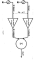
- Fig. 1 In embodiments of the present invention nominally identical signals from non-linear devices or circuits such as amplifiers are combined with a phase difference between the outputs as shown schematically in Fig. 1 .
- two input signals such as signals to be transmitted from an RF transmitter are supplied to two non-linear amplifiers.
- the input signals are 90° out of phase.
- the outputs from the two amplifiers are added.
- the second harmonic distortion is cancelled after amplification.
- the input signals can be modulated with an information signal, e.g. a voice or data signal, e.g. as found in a wireless phone, a modem, a base station, etc.
- the summing instead of summing after amplifiers, the summing can be done after other non-linear devices such as after duplicated mixers. In this way, for example, the second harmonic distortion of the mixer can be cancelled before amplification.
- a non-linear system can be characterized by a transfer function.
- phase difference is generated is not considered to be a limitation on the present invention.
- the skilled person is aware or how to provide phase differences such as the above in a baseband signal in the digital domain.
- the present invention find particular use in transmitters, e.g. of RF wireless transceivers or transmitters in which the outputs of two nominally identical amplifiers or mixers are summed to generate an output signal that has at least one harmonic cancelled.
- the transmitter can be a stand-alone transmitter or part of a transceiver.
- the radio front-end includes a radio upconversion device, e.g. comprising RF filters, a quadrature frequency synthesizer, and image-reject mixers to process input signals up to high frequencies.
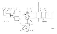
- a radio signal to be transmitted is supplied to an antenna 50 and this radio signal is the result of processing by a radio front end upconversion device including a transmission band-pass filter 52, power amplifiers 54, 55, analog image-reject mixers 56, 57 and a low pass filter 58.
- a radio front end upconversion device including a transmission band-pass filter 52, power amplifiers 54, 55, analog image-reject mixers 56, 57 and a low pass filter 58.
- each image reject upconversion mixer 56, 57 both the baseband signal and the LO signal inputs are quadrature (I,Q) signals.
- the frequency synthesiser 40 can include an oscillator 44 at double the channel frequency followed by a divider by 2, (42).
- the quadrature signal is generated in digital domain.
- the baseband source signal is processed in a unit 69 which can include a source coder, a modulator etc. Outputs of the unit 69 are the I and Q digital signals.
- a DAC 66 the IQ signals received from unit 68 are converted to IQ analog signals.
- two amplifiers are used 54, 55 each having an input that is 90° out of phase with the other. Hence the outputs of the amplifiers are also 90° out of phase with each other.
- the mixer units 56, 57 each receive the IQ signals from filter 58 and mix with IQ signals from the quadrature frequency synthesiser 40 to upregulate the IQ signals.
- the upregulated IQ signals are supplied to nominally identical power amplifiers 54, 55.
- the outputs of the amplifiers 54, 55 are summed and fed to the antenna 50 via a filter 52.
- phase difference between the IQ signals is 90° the second harmonic at least is cancelled in the summed outputs of amplifiers 54, 55.
Landscapes
- Engineering & Computer Science (AREA)
- Power Engineering (AREA)
- Transmitters (AREA)
- Supply And Distribution Of Alternating Current (AREA)
Priority Applications (2)
| Application Number | Priority Date | Filing Date | Title |
|---|---|---|---|
| EP08162709A EP2157691A1 (de) | 2008-08-20 | 2008-08-20 | Signalerzeugung mit aufgelösten Oberwellen |
| PCT/EP2009/060639 WO2010020617A2 (en) | 2008-08-20 | 2009-08-17 | Signal generation with cancelled harmonics |
Applications Claiming Priority (1)
| Application Number | Priority Date | Filing Date | Title |
|---|---|---|---|
| EP08162709A EP2157691A1 (de) | 2008-08-20 | 2008-08-20 | Signalerzeugung mit aufgelösten Oberwellen |
Publications (1)
| Publication Number | Publication Date |
|---|---|
| EP2157691A1 true EP2157691A1 (de) | 2010-02-24 |
Family
ID=40740201
Family Applications (1)
| Application Number | Title | Priority Date | Filing Date |
|---|---|---|---|
| EP08162709A Withdrawn EP2157691A1 (de) | 2008-08-20 | 2008-08-20 | Signalerzeugung mit aufgelösten Oberwellen |
Country Status (2)
| Country | Link |
|---|---|
| EP (1) | EP2157691A1 (de) |
| WO (1) | WO2010020617A2 (de) |
Cited By (2)
| Publication number | Priority date | Publication date | Assignee | Title |
|---|---|---|---|---|
| CN102570983A (zh) * | 2012-01-11 | 2012-07-11 | 华为技术有限公司 | 一种谐波抑制方法及电路 |
| CN111682912A (zh) * | 2020-05-29 | 2020-09-18 | 中国科学院微电子研究所 | 一种基于fpga的超宽带功放谐波消除装置及方法 |
Citations (5)
| Publication number | Priority date | Publication date | Assignee | Title |
|---|---|---|---|---|
| US20030007377A1 (en) * | 2001-06-29 | 2003-01-09 | Shoji Otaka | Frequency converter and radio communication apparatus with the same |
| US6766158B1 (en) * | 2001-03-30 | 2004-07-20 | Skyworks Solutions, Inc. | Harmonic cancellation mixer |
| US20040145415A1 (en) * | 2003-01-24 | 2004-07-29 | Bo Sun | High linearity low noise amplifier |
| WO2004107562A1 (en) * | 2003-05-29 | 2004-12-09 | The University Of North Carolina At Charlotte | Method and apparatus for cancellation of third order intermodulation distortion and other nonlinearities |
| US6882191B2 (en) * | 2003-06-23 | 2005-04-19 | M2 Networks, Inc. | Rectifier type frequency doubler with harmonic cancellation |
Family Cites Families (4)
| Publication number | Priority date | Publication date | Assignee | Title |
|---|---|---|---|---|
| EP0305603B1 (de) * | 1987-09-03 | 1993-03-10 | Koninklijke Philips Electronics N.V. | Phasen- und Verstärkungsregelung für einen Empfänger mit zwei Zweigen |
| FI98330C (fi) * | 1994-12-15 | 1997-05-26 | Nokia Mobile Phones Ltd | UHF-syntesoija |
| US7130604B1 (en) * | 2002-06-06 | 2006-10-31 | National Semiconductor Corporation | Harmonic rejection mixer and method of operation |
| US20060115005A1 (en) * | 2004-11-26 | 2006-06-01 | Technoconcepts, Inc. | Direct conversion delta-sigma transmitter |
-
2008
- 2008-08-20 EP EP08162709A patent/EP2157691A1/de not_active Withdrawn
-
2009
- 2009-08-17 WO PCT/EP2009/060639 patent/WO2010020617A2/en not_active Ceased
Patent Citations (5)
| Publication number | Priority date | Publication date | Assignee | Title |
|---|---|---|---|---|
| US6766158B1 (en) * | 2001-03-30 | 2004-07-20 | Skyworks Solutions, Inc. | Harmonic cancellation mixer |
| US20030007377A1 (en) * | 2001-06-29 | 2003-01-09 | Shoji Otaka | Frequency converter and radio communication apparatus with the same |
| US20040145415A1 (en) * | 2003-01-24 | 2004-07-29 | Bo Sun | High linearity low noise amplifier |
| WO2004107562A1 (en) * | 2003-05-29 | 2004-12-09 | The University Of North Carolina At Charlotte | Method and apparatus for cancellation of third order intermodulation distortion and other nonlinearities |
| US6882191B2 (en) * | 2003-06-23 | 2005-04-19 | M2 Networks, Inc. | Rectifier type frequency doubler with harmonic cancellation |
Cited By (4)
| Publication number | Priority date | Publication date | Assignee | Title |
|---|---|---|---|---|
| CN102570983A (zh) * | 2012-01-11 | 2012-07-11 | 华为技术有限公司 | 一种谐波抑制方法及电路 |
| CN102570983B (zh) * | 2012-01-11 | 2015-01-21 | 华为技术有限公司 | 一种谐波抑制方法及电路 |
| CN111682912A (zh) * | 2020-05-29 | 2020-09-18 | 中国科学院微电子研究所 | 一种基于fpga的超宽带功放谐波消除装置及方法 |
| CN111682912B (zh) * | 2020-05-29 | 2022-03-08 | 中国科学院微电子研究所 | 一种基于fpga的超宽带功放谐波消除装置及方法 |
Also Published As
| Publication number | Publication date |
|---|---|
| WO2010020617A3 (en) | 2010-07-01 |
| WO2010020617A2 (en) | 2010-02-25 |
Similar Documents
| Publication | Publication Date | Title |
|---|---|---|
| CN101453226B (zh) | 本振泄漏消除装置及方法 | |
| KR101240044B1 (ko) | 고조파 배제 믹서를 구현하기 위한 시스템 및 방법 | |
| US6975686B1 (en) | IQ modulation systems and methods that use separate phase and amplitude signal paths | |
| US7817970B2 (en) | Transmitting/receiving device having a polar modulator with variable predistortion | |
| KR100335713B1 (ko) | I/q직교위상변조기회로 | |
| US6850749B2 (en) | Local oscillator architecture to reduce transmitter pulling effect and minimize unwanted sideband | |
| EP0877476A1 (de) | Mischer zur Abwärtsumsetzung | |
| US9054642B2 (en) | Systems and methods to provide compensated feedback phase information | |
| CN100459414C (zh) | 射频混合器装置 | |
| JPH08242261A (ja) | 検波器及び受信装置並びに送信装置 | |
| US6631254B1 (en) | Apparatus for producing a radio-frequency signal | |
| JPH05502358A (ja) | 無線通信システム用周波数コンバータ | |
| WO2024255895A9 (zh) | 信号发射、校准、补偿及收发链路,集成电路、电磁波传感器及设备 | |
| US6094571A (en) | Differential class AB mixer circuit | |
| KR20130079868A (ko) | 밸런스 구조의 fmcw 레이더 장치 | |
| EP2157691A1 (de) | Signalerzeugung mit aufgelösten Oberwellen | |
| US4464791A (en) | All-level Rayleigh fader | |
| US7542739B2 (en) | Up converter mixer linearization improvement | |
| US20140029694A1 (en) | Signal transmitting device and signal transmitting method | |
| Eroglu | Non-invasive quadrature modulator balancing method to optimize image band rejection | |
| US7415077B2 (en) | Transmission arrangement, particularly for mobile radio | |
| US8913693B2 (en) | Quadrature modulator balancing system | |
| JP5553927B2 (ja) | 半導体装置及び無線通信機 | |
| Heuermann | Detectors and Mixers | |
| US7876169B2 (en) | Modulating circuit |
Legal Events
| Date | Code | Title | Description |
|---|---|---|---|
| PUAI | Public reference made under article 153(3) epc to a published international application that has entered the european phase |
Free format text: ORIGINAL CODE: 0009012 |
|
| AK | Designated contracting states |
Kind code of ref document: A1 Designated state(s): AT BE BG CH CY CZ DE DK EE ES FI FR GB GR HR HU IE IS IT LI LT LU LV MC MT NL NO PL PT RO SE SI SK TR |
|
| AX | Request for extension of the european patent |
Extension state: AL BA MK RS |
|
| 17P | Request for examination filed |
Effective date: 20100824 |
|
| 17Q | First examination report despatched |
Effective date: 20100923 |
|
| AKX | Designation fees paid |
Designated state(s): AT BE BG CH CY CZ DE DK EE ES FI FR GB GR HR HU IE IS IT LI LT LU LV MC MT NL NO PL PT RO SE SI SK TR |
|
| STAA | Information on the status of an ep patent application or granted ep patent |
Free format text: STATUS: THE APPLICATION IS DEEMED TO BE WITHDRAWN |
|
| 18D | Application deemed to be withdrawn |
Effective date: 20110203 |