EP2158048B1 - Procédé de fabrication de réservoirs - Google Patents
Procédé de fabrication de réservoirs Download PDFInfo
- Publication number
- EP2158048B1 EP2158048B1 EP08737265A EP08737265A EP2158048B1 EP 2158048 B1 EP2158048 B1 EP 2158048B1 EP 08737265 A EP08737265 A EP 08737265A EP 08737265 A EP08737265 A EP 08737265A EP 2158048 B1 EP2158048 B1 EP 2158048B1
- Authority
- EP
- European Patent Office
- Prior art keywords
- tube
- friction stir
- cold working
- alloys
- temperature
- Prior art date
- Legal status (The legal status is an assumption and is not a legal conclusion. Google has not performed a legal analysis and makes no representation as to the accuracy of the status listed.)
- Not-in-force
Links
Images
Classifications
-
- F—MECHANICAL ENGINEERING; LIGHTING; HEATING; WEAPONS; BLASTING
- F17—STORING OR DISTRIBUTING GASES OR LIQUIDS
- F17C—VESSELS FOR CONTAINING OR STORING COMPRESSED, LIQUEFIED OR SOLIDIFIED GASES; FIXED-CAPACITY GAS-HOLDERS; FILLING VESSELS WITH, OR DISCHARGING FROM VESSELS, COMPRESSED, LIQUEFIED, OR SOLIDIFIED GASES
- F17C13/00—Details of vessels or of the filling or discharging of vessels
-
- B—PERFORMING OPERATIONS; TRANSPORTING
- B21—MECHANICAL METAL-WORKING WITHOUT ESSENTIALLY REMOVING MATERIAL; PUNCHING METAL
- B21C—MANUFACTURE OF METAL SHEETS, WIRE, RODS, TUBES, PROFILES OR LIKE SEMI-MANUFACTURED PRODUCTS OTHERWISE THAN BY ROLLING; AUXILIARY OPERATIONS USED IN CONNECTION WITH METAL-WORKING WITHOUT ESSENTIALLY REMOVING MATERIAL
- B21C37/00—Manufacture of metal sheets, rods, wire, tubes, profiles or like semi-manufactured products, not otherwise provided for; Manufacture of tubes of special shape
- B21C37/06—Manufacture of metal sheets, rods, wire, tubes, profiles or like semi-manufactured products, not otherwise provided for; Manufacture of tubes of special shape of tubes or metal hoses; Combined procedures for making tubes, e.g. for making multi-wall tubes
- B21C37/08—Making tubes with welded or soldered seams
- B21C37/0807—Tube treating or manipulating combined with, or specially adapted for use in connection with tube making machines, e.g. drawing-off devices, cutting-off
- B21C37/0811—Tube treating or manipulating combined with, or specially adapted for use in connection with tube making machines, e.g. drawing-off devices, cutting-off removing or treating the weld bead
-
- B—PERFORMING OPERATIONS; TRANSPORTING
- B21—MECHANICAL METAL-WORKING WITHOUT ESSENTIALLY REMOVING MATERIAL; PUNCHING METAL
- B21D—WORKING OR PROCESSING OF SHEET METAL OR METAL TUBES, RODS OR PROFILES WITHOUT ESSENTIALLY REMOVING MATERIAL; PUNCHING METAL
- B21D51/00—Making hollow objects
- B21D51/16—Making hollow objects characterised by the use of the objects
- B21D51/18—Making hollow objects characterised by the use of the objects vessels, e.g. tubs, vats, tanks, sinks, or the like
-
- B—PERFORMING OPERATIONS; TRANSPORTING
- B23—MACHINE TOOLS; METAL-WORKING NOT OTHERWISE PROVIDED FOR
- B23K—SOLDERING OR UNSOLDERING; WELDING; CLADDING OR PLATING BY SOLDERING OR WELDING; CUTTING BY APPLYING HEAT LOCALLY, e.g. FLAME CUTTING; WORKING BY LASER BEAM
- B23K20/00—Non-electric welding by applying impact or other pressure, with or without the application of heat, e.g. cladding or plating
- B23K20/12—Non-electric welding by applying impact or other pressure, with or without the application of heat, e.g. cladding or plating the heat being generated by friction; Friction welding
- B23K20/122—Non-electric welding by applying impact or other pressure, with or without the application of heat, e.g. cladding or plating the heat being generated by friction; Friction welding using a non-consumable tool, e.g. friction stir welding
- B23K20/1225—Particular aspects of welding with a non-consumable tool
-
- B—PERFORMING OPERATIONS; TRANSPORTING
- B23—MACHINE TOOLS; METAL-WORKING NOT OTHERWISE PROVIDED FOR
- B23K—SOLDERING OR UNSOLDERING; WELDING; CLADDING OR PLATING BY SOLDERING OR WELDING; CUTTING BY APPLYING HEAT LOCALLY, e.g. FLAME CUTTING; WORKING BY LASER BEAM
- B23K20/00—Non-electric welding by applying impact or other pressure, with or without the application of heat, e.g. cladding or plating
- B23K20/12—Non-electric welding by applying impact or other pressure, with or without the application of heat, e.g. cladding or plating the heat being generated by friction; Friction welding
- B23K20/129—Non-electric welding by applying impact or other pressure, with or without the application of heat, e.g. cladding or plating the heat being generated by friction; Friction welding specially adapted for particular articles or work
-
- F—MECHANICAL ENGINEERING; LIGHTING; HEATING; WEAPONS; BLASTING
- F17—STORING OR DISTRIBUTING GASES OR LIQUIDS
- F17C—VESSELS FOR CONTAINING OR STORING COMPRESSED, LIQUEFIED OR SOLIDIFIED GASES; FIXED-CAPACITY GAS-HOLDERS; FILLING VESSELS WITH, OR DISCHARGING FROM VESSELS, COMPRESSED, LIQUEFIED, OR SOLIDIFIED GASES
- F17C1/00—Pressure vessels, e.g. gas cylinder, gas tank, replaceable cartridge
-
- B—PERFORMING OPERATIONS; TRANSPORTING
- B23—MACHINE TOOLS; METAL-WORKING NOT OTHERWISE PROVIDED FOR
- B23K—SOLDERING OR UNSOLDERING; WELDING; CLADDING OR PLATING BY SOLDERING OR WELDING; CUTTING BY APPLYING HEAT LOCALLY, e.g. FLAME CUTTING; WORKING BY LASER BEAM
- B23K2101/00—Articles made by soldering, welding or cutting
- B23K2101/04—Tubular or hollow articles
- B23K2101/12—Vessels
-
- B—PERFORMING OPERATIONS; TRANSPORTING
- B23—MACHINE TOOLS; METAL-WORKING NOT OTHERWISE PROVIDED FOR
- B23K—SOLDERING OR UNSOLDERING; WELDING; CLADDING OR PLATING BY SOLDERING OR WELDING; CUTTING BY APPLYING HEAT LOCALLY, e.g. FLAME CUTTING; WORKING BY LASER BEAM
- B23K2103/00—Materials to be soldered, welded or cut
- B23K2103/08—Non-ferrous metals or alloys
- B23K2103/10—Aluminium or alloys thereof
Definitions
- This invention relates to a method of making friction stir welded metal tanks or liners for use in a pressure vessel from flat plate and to a friction stir welded tank or liner (see e.g US-B-6 364 197 ).
- Tanks are containers intended to store a fluid, in particular gas, probably, but not necessarily, under pressure.
- the term tank thus embraces items commonly used for gas storage, such as cylinders, and liners for use in pressure vessels.
- Cylindrical metal tanks are known and the cylindrical part is typically formed by extrusion, and at least one end closed by preformed elements welded to the cylindrical part, or by a hot or cold working process.
- WO 2004/096459 describes the manufacture of aluminium cylinders from tubes produced by extrusion through a porthole die. The longitudinal welds formed during the extrusion process are conditioned by running a rotating probe along the extrusion welds. This is said to have the effect of producing finely divided crystal grains in the weld regions. Solution treatment in this case appears to be carried out during extrusion and before the probe is applied.
- the starting material is a plate of metal preferably an alloy capable of being hardened by heat treatment for example by precipitation hardening.
- the plate is rolled into a tube so that its opposite parallel edges are brought together to face one another, and the facing edges areas are welded.
- a similar technique is known for the manufacture of steel cylinders; for example, US 5,152,452 , describes the manufacture of steel cylinders for the storage of high pressure fluids. The method involves cold rolling a steel plate into a tube and welding along the joint using fusion welding such as TIG, MIG or electron beam welding. The ends of the cylinder are subsequently formed by swaging.
- Friction stir welding is a relatively new technique.
- the basic process is described, for example, in WO 93/10935 and is typically used to join two workpieces.
- the process involves plunging a rotating or reciprocating probe into the workpieces to be joined, and moving the probe along the line of the join.
- the heat generated by the frictional engagement of the probe with the workpieces generates an area of plasticised material which, after passage of the probe, joins across the join line to weld the workpieces together.
- Friction stir welding is capable of providing joints having better mechanical properties than can be obtained by fusion welding processes such as TIG or MIG.
- the grain size in the weld region may be refined. Unfortunately, this refined grain size, because it is heavily worked, may be unstable and prone to develop excessively large grains during subsequent heat treatment. Such large grains in the heat treated weld zone are unacceptable in tanks especially in tanks designed to contain fluids under pressure.
- the present invention provides a method of manufacturing heat treated friction stir welded tanks that avoids the presence of large grains in the final tank.
- a method of manufacturing a tank or liner for use in a pressure vessel comprising the steps of:
- the metal tubes are preferably made from alloys that can be strengthened by heat treatment. This allows the plate to be conveniently shaped into a cylinder before welding and the subsequent cold working operations to be carried out.
- heat treatable alloys include those that can be strengthened by some means, for example by precipitation hardening using for example, aluminium alloys.
- Other alloys that may be strengthened using precipitation hardening include magnesium alloys, copper alloys, titanium alloys, nickel alloys or steels. Phase transformation techniques may also be used for hardening , for example with steels.
- Precipitation hardenable aluminium alloys are particularly preferred especially the AA2000, AA6000, AA7000 and AA8000 series as defined in the International Alloy Designations and Chemical Composition Limits for Wrought Aluminum and Aluminum Alloys published by The Aluminum Association as revised January 2001 .
- Specific preferred aluminium alloys are AA6061, AA7032, AA7060 and AA7475.
- Precipitation hardening includes a solution treatment to take soluble elements into solution followed by a low temperature precipitation treatment.
- plate is intended to cover rectangular or square plates and plates shaped to suit rolling into a tube that does not have a uniform cross section along its length.
- the plate may be of uniform or variable thickness.
- plate means rolled product with a thickness of not less than 0,152mm (0.006 inches). This includes sheet, which generally has a thickness between 0,152mm (0.006 inches) and 6,35mm (0.250 inches) and plate having a thickness of not less than 6,35mm (0.250 inches).
- At least part of the friction stir weld is subjected to cold working.
- cold working we mean deformation at a temperature below that at which significant recovery or recrystallisation occurs in the weld or in the parent metal.
- Drawing is one example of a cold working operation that can be applied to a cylinder. Ironing is another example.
- the welded tank is heat treated after friction stir welding and cold working.
- the heat treatment step may comprise annealing at a temperature that allows significant recovery or preferably recrystallisation to occur. In aluminium alloys, a suitable annealing treatment may be carried out at 350 to 475°C.
- the heat treatment step may comprise solution treatment in which a heat treatment step is followed by cooling at a rate sufficient to keep all or most of the soluble elements in solution. Solution treatment is carried out by heating the alloy to a temperature at which all or most of the soluble elements are taken into solution (typically 400 to 545°C for aluminium alloys) and then cooling at a sufficient rate to hold most or all of the soluble elements in solution.
- the solution treated alloy may then be subjected to a precipitation treatment at room temperature or an elevated temperature for example 90-200°C, preferably 105-200°C, to increase the strength.
- the age hardening may be carried out in a single step at a substantially constant temperature. Alternatively it may involve two or more stages each stage at a different temperature.
- a friction stir welded joint may exhibit excessive grain growth when subjected to heat treatment under conditions where recrystallisation can occur. Suitable conditions for grain growth arise during annealing and during solution treatment.
- Solution heat treatment of friction stir welded joints in aluminium alloys is discussed in US 2005/0011932 .
- the problem addressed in this patent application arises as a result of increased crystalline grain size which occurs during solution heat treatment in that part of the joint which has been subjected to plastic deformation during the friction stir welding process. Since a coarse grain structure is not favourable to good mechanical characteristics, it transpires that a process (solution heat treatment) which is intended to improve mechanical properties actually degrades them in a critical area, namely along the welded joint line.
- US2005/0011932 describes a method of avoiding the growth of coarse grains by adjusting the heat treatment conditions before friction stir welding.
- the solution heat treatment step is preceded by the step of subjecting at least part of the friction stir welded region of the welded tube to a cold working operation.
- a cold working operation Preferably this is a cold drawing operation or an ironing operation i.e. one carried out at a temperature of less than 100 °C.
- the cold working operation will itself have the effect of modifying the grain shape in the as cold worked cylinder but, more importantly, it has been found that the drawing operation has the effect of acting against the tendency of a subsequent heat treatment to increase grain size in the friction stir welded area.
- the amount of cold working required will depend on the composition of the alloy, the friction stir welding conditions and the heat treatment cycle used. The amount chosen must be sufficient to avoid secondary grain growth in both the parent and the weld metal. Secondary grain growth is particularly prone to occur at relatively low degrees of cold work.
- Cold working by drawing reduces or expands the cylinder diameter, and reduces the wall thickness of the cylinder.
- the wall thickness of the cylinder will be reduced from 5mm to 2.5mm - a thickness reduction of 50%.
- cold working is sufficient to avoid the growth of coarse grains during solution treatment. Larger amounts of cold work will probably require a multi-stage drawing operation, with annealing of the cylinder being carried out between each stage.
- only the central part of the cylinder is subjected to drawing, leaving the ends at their original thickness so that they are ready for the step of forming the ends of the cylinder - see below.
- the whole length of the cylinder can be subject to the drawing operation, but the ends are subjected to a lesser degree of drawing so that the wall thickness at the ends is greater, ready for the step of forming the ends.
- abrasion can be confined to the welded area, but preferably the whole of the inside and outside surfaces of the cylinder are abraded to provide a completely uniform surface preparatory to the drawing operation.
- Abrasion can be realised by a sanding or grinding process.
- the final step in the manufacturing process - that of forming the ends - can be carried out by attaching pre-formed ends by welding and/or by necking down the cylinder end by a forming process such as spinning or swaging.
- a forming process such as spinning or swaging.
- the end or ends of the tube to be formed have a greater wall thickness than the remainder of the tube so that there is a sufficient thickness of metal to carry out the spin forming process. This can be achieved by machining but, as described above, the drawing operation can be used to create a cylinder whose ends are thicker than the central part. Thus it is simply a matter of choosing an appropriate thickness for the plate used as the starting material.
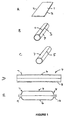
- Figure 1 comprises a series of drawings labelled A to E showing diagrammatically the stages in the formation of a cylinder from a rectangular plate.
- the manufacturing process starts with a square or rectangular plate 1 having opposite parallel edges 2, 3.
- the plate is made of aluminium alloy such as AA6061 alloy.
- the alloy is preferably annealed before starting in order to prevent damage during the subsequent processes.
- the thickness of the plate will depend upon the desired wall thickness for the cylinder. Typically, for fabricating a liner, the plate thickness might be about 5mm.
- the plate 1 is roll formed into an open circular tube 4 ( Figure 1B ) and is placed in a clamping fixture (not shown) so that the edges 2, 3 are pushed together ( Figure 1 C) to form a line 5 extending longitudinally of the cylinder. Friction stir welding is now carried out along the line 5 to join the edges 2, 3 together by a single longitudinal weld line.
- friction stir welding is carried out by drawing a rotating or reciprocating probe through the workpiece, along the weld line.
- the whole thickness of the plate is welded since a weld through only part of the thickness will inevitably leave a line of irregularity, and therefore weakness, on the surface, most likely the inside surface, where the weld has not penetrated.
- the probe penetrates sufficiently deeply into the joint thickness to ensure welding right through and, in practice, this will usually mean that the probe itself penetrates right through the workpiece during welding.
- the tube could also be fabricated by two or more rectangular plates which are roll formed into arcuate members which can then be clamped in a fixture to form a tube and friction stir welded by means of multiple longitudinal welds.
- two rectangular plates could be roll formed into respective 180° arcuate members which could then be joined to form a circular tube by means of two friction stir welded joints.
- the welded tube is next subjected to a sanding process in which the inside and outside surfaces of the cylinder are rotation sanded to provide a uniform surface, free from rolling, machining or welding irregularities. This is intended to remove stress points during the subsequent operations.
- the tube is annealed to an "O" condition, and then lubricant is applied to the inner and outer surfaces in order to prepare the tube for the next operation.
- the welded tube is next subjected to a drawing operation during which the length of the tube increases, and its wall thickness decreases, typically by about 50%.
- the drawing operation which is carried out cold - i.e. at less than 100°C - involves forcing the tube into a suitably shaped die.
- the result of the drawing operation is shown in Figure 1D , and it will be seen that the wall thickness of the central portion 6 of the tube 4 has reduced, but that at the ends 7, 8 is greater. The reason for this difference is to leave the ends with a sufficient thickness of material to withstand the subsequent forming operations carried out on the ends (see below). If preformed ends are to be used, then the thickened walls at the ends are not needed, and the whole length of the tube can be subject to drawing.
- the wall thickness in the central area 6 will be about 2.5mm, while the end regions 7, 8 remain at 5mm wall thickness, or may be subject to just a small amount of drawing, reducing the wall thickness by a lesser amount.
- the thickened ends 7, 8 of the tube are next trimmed to the required length, if necessary, and are subject to a hot spin forming process to dome the ends and form respective necks 9, 10, as illustrated in Figure 1E .
- a hot spin forming process to dome the ends and form respective necks 9, 10, as illustrated in Figure 1E .
- the exact shape of the ends will be dictated by the particular requirements; for example, one end may be closed off completely.
- the semi-finished cylinder is now subject to solution heat treatment. During this treatment the cylinder is heat treated to about 1000°F (537°C), subjected to rapid water quenching to a T4 condition, and then artificially aged to a T6 condition.
- solution heat treatment is to improve the mechanical strength of the material, particularly in the weld area.
- solution heat treatment has the effect of increasing the crystalline grain size and this degrades certain mechanical properties such as ductility and fracture strength which are, of course, important for pressurised containers.
- the cold drawing operation has been found to counter this effect, preventing, or at least reducing, the formation of coarse grains during solution heat treatment.
- the finished cylinder can be used as is for storing pressurised and non-pressurised fluids.
- the cylinder can also be used as a liner in a composite wrapped cylinder, for example in composite hoop wrapped cylinders or composite full wrapped cylinders employing, typically, carbon fibre filament for wrapping.
Landscapes
- Engineering & Computer Science (AREA)
- Mechanical Engineering (AREA)
- General Engineering & Computer Science (AREA)
- Pressure Welding/Diffusion-Bonding (AREA)
- Filling Or Discharging Of Gas Storage Vessels (AREA)
- Pressure Vessels And Lids Thereof (AREA)
- Moulding By Coating Moulds (AREA)
- Air Transport Of Granular Materials (AREA)
- Electrical Discharge Machining, Electrochemical Machining, And Combined Machining (AREA)
Claims (16)
- Un procédé de fabrication d'un réservoir ou d'un revêtement intérieur pour une utilisation dans une cuve sous pression, ledit procédé comprenant les opérations suivantes :a) la formation d'une ou plusieurs plaques métalliques (1) dans un tube (4) avec une paire de bords opposés (2, 3) se faisant face de façon à former une ligne de jonction longitudinale, etb) le soudage par friction-malaxage des bords opposés (2, 3) l'un contre l'autre le long de la ligne de jonction,c) le travail à froid d'au moins une partie de la zone soudée par friction-malaxage, etd) le traitement à chaud du tube (4) à une température supérieure à la température de recristallisation après le travail à froid.
- Un procédé selon la Revendication 1, où lesdites une ou plusieurs plaques métalliques (1) contiennent un alliage d'aluminium.
- Un procédé selon la Revendication 1 ou 2, où l'opération de traitement à chaud comprend une opération de recuit dans une plage de température de 350 à 475°C.
- Un procédé selon la Revendication 1 ou 2 où l'opération de traitement à chaud comprend un traitement en solution grâce auquel tous les ou la plupart des éléments solubles sont mis en solution.
- Un procédé selon la Revendication 4 où, au cours du traitement en solution, le tube (4) est chauffé à une température se situant entre 400 et 545°C et est ensuite refroidi, éventuellement par trempage dans l'air ou dans l'eau, à une vitesse capable de maintenir la plupart ou tous les éléments solubles en solution.
- Un procédé selon la Revendication 4 ou 5 où, suite au traitement en solution, le tube (4) est soumis à un durcissement par précipitation à température ambiante et/ou à une ou plusieurs opérations de durcissement par précipitation à une température élevée, la température élevée se situant de préférence dans la plage allant de 90 à 200°C.
- Un procédé selon l'une quelconque des Revendications précédentes où le travail à froid est réalisé à une température inférieure à 100°C.
- Un procédé selon la Revendication 7, où l'opération de travail à froid comprend une opération d'étirage à froid et/ou de chaudronnage.
- Un procédé selon la Revendication 8 où l'opération de travail à froid réduit l'épaisseur du tube (4) de plus de 20%.
- Un procédé selon l'une quelconque des Revendications 7 à 9, où une ou plusieurs opérations de recuit sont exécutées, l'opération ou chaque opération de recuit étant exécutée avant, entre ou après une ou plusieurs opérations de travail à froid.
- Un procédé selon la Revendication 8, où uniquement la partie centrale du tube (4) est soumise à étirage laissant l'épaisseur des extrémités du tube (4) sensiblement non altérée ou réduite dans une moindre mesure que la partie centrale.
- Un procédé selon l'une quelconque des Revendications précédentes où le tube (4) est formé à partir d'alliages d'aluminium durcissables par précipitation.
- Un procédé selon l'une quelconque des Revendications 1 à 11, où le tube (4) est formé à partir d'un ou plusieurs alliages du groupe se composant d'alliages de magnésium, d'alliages de cuivre, d'alliages de titane, d'alliages de nickel ou d'aciers.
- Un procédé selon la Revendication 13 où les alliages d'aluminium sont choisis parmi les séries AA2000, AA6000, AA7000 et AA8000, et de préférence dans le groupe se composant de AA6061, AA7032 et AA7475.
- Un réservoir métallique ou un revêtement intérieur pour une cuve sous pression possédant une soudure par friction-malaxage le long d'au moins une partie de sa longueur, au moins une partie de la zone de soudure ayant été soumise à des opérations de travail à froid et de traitement à chaud grâce auxquelles ladite au moins une partie de la zone de soudure possède une résistance à l'éclatement plus élevée que le métal parent entourant la zone de soudure.
- Un réservoir métallique ou un revêtement intérieur selon la Revendication 15 où la zone de soudure possède sensiblement la même épaisseur que le métal parent l'entourant.
Applications Claiming Priority (2)
| Application Number | Priority Date | Filing Date | Title |
|---|---|---|---|
| US11/747,497 US20080277036A1 (en) | 2007-05-11 | 2007-05-11 | Method for manufacturing tanks |
| PCT/GB2008/050341 WO2008139222A1 (fr) | 2007-05-11 | 2008-05-09 | Procédé de fabrication de réservoirs |
Publications (2)
| Publication Number | Publication Date |
|---|---|
| EP2158048A1 EP2158048A1 (fr) | 2010-03-03 |
| EP2158048B1 true EP2158048B1 (fr) | 2010-07-28 |
Family
ID=39743094
Family Applications (1)
| Application Number | Title | Priority Date | Filing Date |
|---|---|---|---|
| EP08737265A Not-in-force EP2158048B1 (fr) | 2007-05-11 | 2008-05-09 | Procédé de fabrication de réservoirs |
Country Status (10)
| Country | Link |
|---|---|
| US (2) | US20080277036A1 (fr) |
| EP (1) | EP2158048B1 (fr) |
| JP (1) | JP5346013B2 (fr) |
| AT (1) | ATE475496T1 (fr) |
| AU (1) | AU2008249760B2 (fr) |
| BR (1) | BRPI0811314A2 (fr) |
| DE (1) | DE602008001986D1 (fr) |
| ES (1) | ES2349791T3 (fr) |
| MX (1) | MX2009012146A (fr) |
| WO (1) | WO2008139222A1 (fr) |
Families Citing this family (23)
| Publication number | Priority date | Publication date | Assignee | Title |
|---|---|---|---|---|
| EP2430352B1 (fr) | 2010-02-26 | 2013-08-21 | Faber Industrie S.p.A. | Procédé et système pour produire une information de repérage pour bouteilles de gaz |
| JP5769003B2 (ja) * | 2010-12-24 | 2015-08-26 | 住友電気工業株式会社 | マグネシウム合金材 |
| US9004068B2 (en) | 2011-05-25 | 2015-04-14 | Scott Technologies, Inc. | High pressure air cylinders for use with self-contained breathing apparatus |
| KR101291334B1 (ko) * | 2011-06-13 | 2013-08-05 | (주)태광테크 | 대구경 선회베어링 제조방법 및 이를 이용하여 제조된 대구경 선회베어링 |
| JP5431426B2 (ja) * | 2011-08-23 | 2014-03-05 | 株式会社日立製作所 | Ni基合金大型部材及びNi基合金大型部材を使用したNi基合金溶接構造物とその製造方法 |
| CN104936718B (zh) * | 2012-05-02 | 2019-11-19 | 恩特格里斯公司 | 用于普通圆柱三维共形内衬的制造方法 |
| KR101422584B1 (ko) * | 2013-01-11 | 2014-07-24 | 주식회사 우신이엠시 | 마찰교반용접방법 |
| US20140261900A1 (en) * | 2013-03-12 | 2014-09-18 | Lockheed Martin Corporation | Friction surface stir process |
| FR3003190B1 (fr) * | 2013-03-14 | 2015-04-03 | Luxfer Gas Cylinders Ltd | Procede de fabrication de liners pour reservoir sous pression |
| WO2014174845A1 (fr) * | 2013-04-26 | 2014-10-30 | Jfeスチール株式会社 | Accumulateur |
| EP2799178B1 (fr) * | 2013-05-02 | 2018-07-11 | Volvo Car Corporation | Procédé de création d'un ensemble en acier trempé |
| CN103231218B (zh) * | 2013-05-11 | 2015-09-30 | 哈尔滨工业大学(威海) | 一种钛合金管材的快速制备方法 |
| JP6403515B2 (ja) | 2014-09-24 | 2018-10-10 | 三菱重工業株式会社 | 接合部処理方法及びドーム部材 |
| EP3272135A4 (fr) * | 2015-03-12 | 2018-11-07 | Startimes Communication Network Technology Co. Ltd | Système audio à services basés sur la localisation |
| CN104862625B (zh) * | 2015-04-30 | 2017-02-01 | 无锡海特铝业有限公司 | 一种称重传感器专用铝合金棒材的固溶热处理工艺 |
| EA029501B1 (ru) * | 2017-02-15 | 2018-04-30 | Олег Евгеньевич БОГАЧЕК | Сосуд из термически неупрочняемого алюминиевого сплава и способ его изготовления |
| AT521614B1 (de) * | 2018-09-17 | 2020-03-15 | Boehm Trading Gmbh | Behälter, insbesondere Druckbehälter |
| JP6698927B1 (ja) * | 2019-08-22 | 2020-05-27 | 株式会社フルヤ金属 | 金属系筒材の製造方法及びそれに用いられる裏当て治具 |
| US11712948B2 (en) * | 2019-11-13 | 2023-08-01 | Honda Motor Co., Ltd. | High strength aluminum alloy door beam |
| KR102230872B1 (ko) * | 2019-12-19 | 2021-03-24 | 주식회사 포스코 | 전착 드럼용 티타늄 링의 제조방법 및 이에 의해 제조된 전착 드럼용 티타늄 링 |
| WO2022010718A1 (fr) * | 2020-07-09 | 2022-01-13 | Lam Research Corporation | Traitement par friction-malaxage pour la résistance à la corrosion |
| CN114413531B (zh) * | 2022-01-11 | 2024-03-01 | 河南新科隆电器有限公司 | 一种冰箱/冷柜用新型储液罐及其加工方法 |
| CN114643461B (zh) * | 2022-04-12 | 2022-09-09 | 绍兴杨鑫金属制品有限公司 | 一种采用焊接后多次拉伸扩涨成型的纱罐制造方法 |
Family Cites Families (22)
| Publication number | Priority date | Publication date | Assignee | Title |
|---|---|---|---|---|
| US3198676A (en) * | 1964-09-24 | 1965-08-03 | Aluminum Co Of America | Thermal treatment of aluminum base alloy article |
| US4477292A (en) * | 1973-10-26 | 1984-10-16 | Aluminum Company Of America | Three-step aging to obtain high strength and corrosion resistance in Al-Zn-Mg-Cu alloys |
| US5108520A (en) * | 1980-02-27 | 1992-04-28 | Aluminum Company Of America | Heat treatment of precipitation hardening alloys |
| US5152452A (en) * | 1992-03-10 | 1992-10-06 | York Industries, Inc. | Pressure vessel and method |
| AUPP470298A0 (en) * | 1998-07-15 | 1998-08-06 | Simmons, Anthony Grant | Vehicle wheel rim section |
| JP2000153377A (ja) * | 2000-01-01 | 2000-06-06 | Hitachi Ltd | 摩擦溶接方法 |
| WO2002008653A1 (fr) * | 2000-07-26 | 2002-01-31 | Aeromet Corporation | Corps tubulaire a caracteristiques deposees et son procede de fabrication |
| US6364197B1 (en) * | 2000-08-04 | 2002-04-02 | The Boeing Company | Friction stir welding of containers from the interior |
| JP4232339B2 (ja) * | 2001-02-06 | 2009-03-04 | 日立電線株式会社 | 摩擦撹拌接合による金属の突合せ接合方法 |
| US20040074949A1 (en) * | 2001-03-07 | 2004-04-22 | Masayuki Narita | Friction agitation joining method flat material for plastic working and closed end sleeve like body |
| JP2002273579A (ja) * | 2001-03-15 | 2002-09-25 | Hitachi Ltd | 鉄基材料の接合方法およびその構造物 |
| JP3507050B2 (ja) * | 2001-09-25 | 2004-03-15 | 住友軽金属工業株式会社 | 摩擦攪拌接合方法 |
| US6638381B2 (en) * | 2001-12-18 | 2003-10-28 | The Boeing Company | Method for preparing ultra-fine grain titanium and titanium-alloy articles and articles prepared thereby |
| US6780525B2 (en) * | 2001-12-26 | 2004-08-24 | The Boeing Company | High strength friction stir welding |
| JP3820393B2 (ja) * | 2002-12-06 | 2006-09-13 | 本田技研工業株式会社 | 円筒体製造用治具 |
| JP2004243410A (ja) * | 2003-01-20 | 2004-09-02 | Nippon Steel Corp | 金属箔チューブおよびその製造方法並びに製造装置 |
| JP4243134B2 (ja) * | 2003-04-25 | 2009-03-25 | 昭和電工株式会社 | 金属筒状体およびその製造方法 |
| JP4445791B2 (ja) * | 2003-04-25 | 2010-04-07 | 昭和電工株式会社 | 圧力容器用ライナおよびその製造方法 |
| WO2004096459A1 (fr) * | 2003-04-25 | 2004-11-11 | Showa Denko K.K. | Corps metallique tubulaire, procede de fabrication associe, revetement pour appareil a pression, et procede de fabrication associe |
| FR2855083B1 (fr) * | 2003-05-20 | 2006-05-26 | Pechiney Rhenalu | Procede de fabrication de pieces en alliage d'aluminium soudees par friction |
| US7614539B2 (en) * | 2004-09-13 | 2009-11-10 | The Boeing Company | Method to improve properties of aluminum alloys processed by solid state joining |
| JP4842693B2 (ja) * | 2006-04-26 | 2011-12-21 | Dowaホールディングス株式会社 | 銅部材の接合方法および摩擦攪拌接合装置 |
-
2007
- 2007-05-11 US US11/747,497 patent/US20080277036A1/en not_active Abandoned
-
2008
- 2008-05-09 ES ES08737265T patent/ES2349791T3/es active Active
- 2008-05-09 JP JP2010507005A patent/JP5346013B2/ja not_active Expired - Fee Related
- 2008-05-09 AU AU2008249760A patent/AU2008249760B2/en not_active Ceased
- 2008-05-09 MX MX2009012146A patent/MX2009012146A/es active IP Right Grant
- 2008-05-09 DE DE602008001986T patent/DE602008001986D1/de active Active
- 2008-05-09 EP EP08737265A patent/EP2158048B1/fr not_active Not-in-force
- 2008-05-09 AT AT08737265T patent/ATE475496T1/de not_active IP Right Cessation
- 2008-05-09 BR BRPI0811314-9A2A patent/BRPI0811314A2/pt not_active IP Right Cessation
- 2008-05-09 WO PCT/GB2008/050341 patent/WO2008139222A1/fr not_active Ceased
-
2013
- 2013-10-03 US US14/045,279 patent/US20140027023A1/en not_active Abandoned
Also Published As
| Publication number | Publication date |
|---|---|
| DE602008001986D1 (de) | 2010-09-09 |
| MX2009012146A (es) | 2010-02-22 |
| EP2158048A1 (fr) | 2010-03-03 |
| ES2349791T3 (es) | 2011-01-11 |
| WO2008139222A1 (fr) | 2008-11-20 |
| JP5346013B2 (ja) | 2013-11-20 |
| US20140027023A1 (en) | 2014-01-30 |
| US20080277036A1 (en) | 2008-11-13 |
| BRPI0811314A2 (pt) | 2015-01-27 |
| ATE475496T1 (de) | 2010-08-15 |
| JP2010530498A (ja) | 2010-09-09 |
| AU2008249760A1 (en) | 2008-11-20 |
| AU2008249760B2 (en) | 2013-12-05 |
Similar Documents
| Publication | Publication Date | Title |
|---|---|---|
| EP2158048B1 (fr) | Procédé de fabrication de réservoirs | |
| Beal et al. | Forming of titanium and titanium alloys | |
| US7601232B2 (en) | α-β titanium alloy tubes and methods of flowforming the same | |
| CN110520668B (zh) | 不可热处理铝合金容器及其制造方法 | |
| CN1816641B (zh) | 钛-铝-钒合金的加工及由其制造的产品 | |
| US6866180B2 (en) | Thick-section metal forming via friction stir processing | |
| EP2142332B1 (fr) | Procédé de fabrication d'une structure souidee en d'alliage 36 ni-fe | |
| EA034923B1 (ru) | Ротационное выдавливание труб из коррозионностойких сплавов и трубы, изготовленные с его использованием | |
| RU2222635C2 (ru) | Способ обработки металлических материалов и заготовка из алюминида титана, полученная этим способом | |
| CN111168207A (zh) | 一种氨制冷容器应力腐蚀裂纹的返修焊缝方法 | |
| RU2510784C1 (ru) | Способ изготовления сварных сосудов высокого давления | |
| CN109604966A (zh) | 一种内腔带网格筋的贮箱筒段整体成形方法 | |
| CN107363473B (zh) | 一种氨气储罐的制造工艺 | |
| KR20140069875A (ko) | 고강도-고연성 층상복합알루미늄합금판재 | |
| JPS5936145B2 (ja) | 圧力容器 | |
| JP3854476B2 (ja) | バースト特性に優れた高強度鋼管の製造方法 | |
| RU87492U1 (ru) | Баллон высокого давления (варианты) | |
| JPH09239569A (ja) | 高圧容器及びその製作方法 | |
| JPS60141823A (ja) | 非磁性エンドリングの製造方法 | |
| US11759837B1 (en) | Systems and methods for launch vehicle dome manufacturing | |
| JPH06234029A (ja) | 溶接継目のない液化ガス容器の製造方法及び溶接継目のない液化ガス容器 | |
| RU2839583C1 (ru) | Способ изготовления формованных изделий из алюминиевого сплава | |
| RU2648343C1 (ru) | СПОСОБ ИЗГОТОВЛЕНИЯ БАЛЛОНОВ, РАБОТАЮЩИХ ПОД ДАВЛЕНИЕМ ДО 250 кгс/см2 | |
| Sgobba et al. | Design, construction, and quality tests of the large Al-alloy mandrels for the CMS coil | |
| Olofson et al. | Assessment of Fabrication Methods for 70 MM LAWT Warhead Bodies |
Legal Events
| Date | Code | Title | Description |
|---|---|---|---|
| PUAI | Public reference made under article 153(3) epc to a published international application that has entered the european phase |
Free format text: ORIGINAL CODE: 0009012 |
|
| 17P | Request for examination filed |
Effective date: 20091201 |
|
| AK | Designated contracting states |
Kind code of ref document: A1 Designated state(s): AT BE BG CH CY CZ DE DK EE ES FI FR GB GR HR HU IE IS IT LI LT LU LV MC MT NL NO PL PT RO SE SI SK TR |
|
| AX | Request for extension of the european patent |
Extension state: AL BA MK RS |
|
| GRAP | Despatch of communication of intention to grant a patent |
Free format text: ORIGINAL CODE: EPIDOSNIGR1 |
|
| GRAS | Grant fee paid |
Free format text: ORIGINAL CODE: EPIDOSNIGR3 |
|
| GRAA | (expected) grant |
Free format text: ORIGINAL CODE: 0009210 |
|
| AK | Designated contracting states |
Kind code of ref document: B1 Designated state(s): AT BE BG CH CY CZ DE DK EE ES FI FR GB GR HR HU IE IS IT LI LT LU LV MC MT NL NO PL PT RO SE SI SK TR |
|
| REG | Reference to a national code |
Ref country code: GB Ref legal event code: FG4D |
|
| REG | Reference to a national code |
Ref country code: CH Ref legal event code: EP |
|
| REG | Reference to a national code |
Ref country code: IE Ref legal event code: FG4D |
|
| REF | Corresponds to: |
Ref document number: 602008001986 Country of ref document: DE Date of ref document: 20100909 Kind code of ref document: P |
|
| REG | Reference to a national code |
Ref country code: CH Ref legal event code: NV Representative=s name: E. BLUM & CO. AG PATENT- UND MARKENANWAELTE VSP |
|
| REG | Reference to a national code |
Ref country code: CH Ref legal event code: PFA Owner name: LUXFER GROUP LIMITED Free format text: LUXFER GROUP LIMITED#VICTORIA HOUSE 150 - 182 THE QUAYS#SALFORD GREATER MANCHESTER M50 3SP (GB) -TRANSFER TO- LUXFER GROUP LIMITED#THE VICTORIA 150-182 HARBOUR CITY SALFORD QUAYS#SALFORD M50 3SP (GB) |
|
| REG | Reference to a national code |
Ref country code: SE Ref legal event code: TRGR |
|
| REG | Reference to a national code |
Ref country code: NL Ref legal event code: T3 |
|
| RAP2 | Party data changed (patent owner data changed or rights of a patent transferred) |
Owner name: LUXFER GROUP LIMITED |
|
| LTIE | Lt: invalidation of european patent or patent extension |
Effective date: 20100728 |
|
| RAP4 | Party data changed (patent owner data changed or rights of a patent transferred) |
Owner name: LUXFER GROUP LIMITED |
|
| REG | Reference to a national code |
Ref country code: ES Ref legal event code: FG2A Effective date: 20101228 |
|
| PG25 | Lapsed in a contracting state [announced via postgrant information from national office to epo] |
Ref country code: NO Free format text: LAPSE BECAUSE OF FAILURE TO SUBMIT A TRANSLATION OF THE DESCRIPTION OR TO PAY THE FEE WITHIN THE PRESCRIBED TIME-LIMIT Effective date: 20101028 Ref country code: LT Free format text: LAPSE BECAUSE OF FAILURE TO SUBMIT A TRANSLATION OF THE DESCRIPTION OR TO PAY THE FEE WITHIN THE PRESCRIBED TIME-LIMIT Effective date: 20100728 Ref country code: FI Free format text: LAPSE BECAUSE OF FAILURE TO SUBMIT A TRANSLATION OF THE DESCRIPTION OR TO PAY THE FEE WITHIN THE PRESCRIBED TIME-LIMIT Effective date: 20100728 Ref country code: AT Free format text: LAPSE BECAUSE OF FAILURE TO SUBMIT A TRANSLATION OF THE DESCRIPTION OR TO PAY THE FEE WITHIN THE PRESCRIBED TIME-LIMIT Effective date: 20100728 |
|
| REG | Reference to a national code |
Ref country code: FR Ref legal event code: CA |
|
| PG25 | Lapsed in a contracting state [announced via postgrant information from national office to epo] |
Ref country code: BG Free format text: LAPSE BECAUSE OF FAILURE TO SUBMIT A TRANSLATION OF THE DESCRIPTION OR TO PAY THE FEE WITHIN THE PRESCRIBED TIME-LIMIT Effective date: 20101028 Ref country code: CY Free format text: LAPSE BECAUSE OF FAILURE TO SUBMIT A TRANSLATION OF THE DESCRIPTION OR TO PAY THE FEE WITHIN THE PRESCRIBED TIME-LIMIT Effective date: 20100728 Ref country code: HR Free format text: LAPSE BECAUSE OF FAILURE TO SUBMIT A TRANSLATION OF THE DESCRIPTION OR TO PAY THE FEE WITHIN THE PRESCRIBED TIME-LIMIT Effective date: 20100728 Ref country code: IS Free format text: LAPSE BECAUSE OF FAILURE TO SUBMIT A TRANSLATION OF THE DESCRIPTION OR TO PAY THE FEE WITHIN THE PRESCRIBED TIME-LIMIT Effective date: 20101128 Ref country code: PL Free format text: LAPSE BECAUSE OF FAILURE TO SUBMIT A TRANSLATION OF THE DESCRIPTION OR TO PAY THE FEE WITHIN THE PRESCRIBED TIME-LIMIT Effective date: 20100728 Ref country code: SI Free format text: LAPSE BECAUSE OF FAILURE TO SUBMIT A TRANSLATION OF THE DESCRIPTION OR TO PAY THE FEE WITHIN THE PRESCRIBED TIME-LIMIT Effective date: 20100728 |
|
| PG25 | Lapsed in a contracting state [announced via postgrant information from national office to epo] |
Ref country code: GR Free format text: LAPSE BECAUSE OF FAILURE TO SUBMIT A TRANSLATION OF THE DESCRIPTION OR TO PAY THE FEE WITHIN THE PRESCRIBED TIME-LIMIT Effective date: 20101029 Ref country code: LV Free format text: LAPSE BECAUSE OF FAILURE TO SUBMIT A TRANSLATION OF THE DESCRIPTION OR TO PAY THE FEE WITHIN THE PRESCRIBED TIME-LIMIT Effective date: 20100728 |
|
| PG25 | Lapsed in a contracting state [announced via postgrant information from national office to epo] |
Ref country code: DK Free format text: LAPSE BECAUSE OF FAILURE TO SUBMIT A TRANSLATION OF THE DESCRIPTION OR TO PAY THE FEE WITHIN THE PRESCRIBED TIME-LIMIT Effective date: 20100728 |
|
| PG25 | Lapsed in a contracting state [announced via postgrant information from national office to epo] |
Ref country code: CZ Free format text: LAPSE BECAUSE OF FAILURE TO SUBMIT A TRANSLATION OF THE DESCRIPTION OR TO PAY THE FEE WITHIN THE PRESCRIBED TIME-LIMIT Effective date: 20100728 Ref country code: EE Free format text: LAPSE BECAUSE OF FAILURE TO SUBMIT A TRANSLATION OF THE DESCRIPTION OR TO PAY THE FEE WITHIN THE PRESCRIBED TIME-LIMIT Effective date: 20100728 Ref country code: SK Free format text: LAPSE BECAUSE OF FAILURE TO SUBMIT A TRANSLATION OF THE DESCRIPTION OR TO PAY THE FEE WITHIN THE PRESCRIBED TIME-LIMIT Effective date: 20100728 Ref country code: RO Free format text: LAPSE BECAUSE OF FAILURE TO SUBMIT A TRANSLATION OF THE DESCRIPTION OR TO PAY THE FEE WITHIN THE PRESCRIBED TIME-LIMIT Effective date: 20100728 |
|
| PLBE | No opposition filed within time limit |
Free format text: ORIGINAL CODE: 0009261 |
|
| STAA | Information on the status of an ep patent application or granted ep patent |
Free format text: STATUS: NO OPPOSITION FILED WITHIN TIME LIMIT |
|
| 26N | No opposition filed |
Effective date: 20110429 |
|
| REG | Reference to a national code |
Ref country code: DE Ref legal event code: R097 Ref document number: 602008001986 Country of ref document: DE Effective date: 20110429 |
|
| PG25 | Lapsed in a contracting state [announced via postgrant information from national office to epo] |
Ref country code: MT Free format text: LAPSE BECAUSE OF FAILURE TO SUBMIT A TRANSLATION OF THE DESCRIPTION OR TO PAY THE FEE WITHIN THE PRESCRIBED TIME-LIMIT Effective date: 20100728 Ref country code: MC Free format text: LAPSE BECAUSE OF NON-PAYMENT OF DUE FEES Effective date: 20110531 |
|
| REG | Reference to a national code |
Ref country code: IE Ref legal event code: MM4A |
|
| PG25 | Lapsed in a contracting state [announced via postgrant information from national office to epo] |
Ref country code: IE Free format text: LAPSE BECAUSE OF NON-PAYMENT OF DUE FEES Effective date: 20110509 |
|
| PG25 | Lapsed in a contracting state [announced via postgrant information from national office to epo] |
Ref country code: LU Free format text: LAPSE BECAUSE OF NON-PAYMENT OF DUE FEES Effective date: 20110509 |
|
| PG25 | Lapsed in a contracting state [announced via postgrant information from national office to epo] |
Ref country code: PT Free format text: LAPSE BECAUSE OF NON-PAYMENT OF DUE FEES Effective date: 20100728 |
|
| PG25 | Lapsed in a contracting state [announced via postgrant information from national office to epo] |
Ref country code: TR Free format text: LAPSE BECAUSE OF FAILURE TO SUBMIT A TRANSLATION OF THE DESCRIPTION OR TO PAY THE FEE WITHIN THE PRESCRIBED TIME-LIMIT Effective date: 20100728 |
|
| PG25 | Lapsed in a contracting state [announced via postgrant information from national office to epo] |
Ref country code: HU Free format text: LAPSE BECAUSE OF FAILURE TO SUBMIT A TRANSLATION OF THE DESCRIPTION OR TO PAY THE FEE WITHIN THE PRESCRIBED TIME-LIMIT Effective date: 20100728 |
|
| REG | Reference to a national code |
Ref country code: FR Ref legal event code: PLFP Year of fee payment: 8 |
|
| REG | Reference to a national code |
Ref country code: FR Ref legal event code: PLFP Year of fee payment: 9 |
|
| PGFP | Annual fee paid to national office [announced via postgrant information from national office to epo] |
Ref country code: NL Payment date: 20160524 Year of fee payment: 9 |
|
| PGFP | Annual fee paid to national office [announced via postgrant information from national office to epo] |
Ref country code: CH Payment date: 20160519 Year of fee payment: 9 Ref country code: ES Payment date: 20160530 Year of fee payment: 9 Ref country code: GB Payment date: 20160415 Year of fee payment: 9 Ref country code: DE Payment date: 20160518 Year of fee payment: 9 |
|
| PGFP | Annual fee paid to national office [announced via postgrant information from national office to epo] |
Ref country code: BE Payment date: 20160524 Year of fee payment: 9 Ref country code: IT Payment date: 20160523 Year of fee payment: 9 Ref country code: FR Payment date: 20160509 Year of fee payment: 9 Ref country code: SE Payment date: 20160520 Year of fee payment: 9 |
|
| REG | Reference to a national code |
Ref country code: DE Ref legal event code: R119 Ref document number: 602008001986 Country of ref document: DE |
|
| REG | Reference to a national code |
Ref country code: CH Ref legal event code: PL |
|
| REG | Reference to a national code |
Ref country code: SE Ref legal event code: EUG |
|
| REG | Reference to a national code |
Ref country code: NL Ref legal event code: MM Effective date: 20170601 |
|
| GBPC | Gb: european patent ceased through non-payment of renewal fee |
Effective date: 20170509 |
|
| PG25 | Lapsed in a contracting state [announced via postgrant information from national office to epo] |
Ref country code: CH Free format text: LAPSE BECAUSE OF NON-PAYMENT OF DUE FEES Effective date: 20170531 Ref country code: SE Free format text: LAPSE BECAUSE OF NON-PAYMENT OF DUE FEES Effective date: 20170510 Ref country code: LI Free format text: LAPSE BECAUSE OF NON-PAYMENT OF DUE FEES Effective date: 20170531 |
|
| REG | Reference to a national code |
Ref country code: FR Ref legal event code: ST Effective date: 20180131 |
|
| PG25 | Lapsed in a contracting state [announced via postgrant information from national office to epo] |
Ref country code: NL Free format text: LAPSE BECAUSE OF NON-PAYMENT OF DUE FEES Effective date: 20170601 |
|
| REG | Reference to a national code |
Ref country code: BE Ref legal event code: MM Effective date: 20170531 |
|
| PG25 | Lapsed in a contracting state [announced via postgrant information from national office to epo] |
Ref country code: GB Free format text: LAPSE BECAUSE OF NON-PAYMENT OF DUE FEES Effective date: 20170509 Ref country code: DE Free format text: LAPSE BECAUSE OF NON-PAYMENT OF DUE FEES Effective date: 20171201 |
|
| PG25 | Lapsed in a contracting state [announced via postgrant information from national office to epo] |
Ref country code: FR Free format text: LAPSE BECAUSE OF NON-PAYMENT OF DUE FEES Effective date: 20170531 Ref country code: IT Free format text: LAPSE BECAUSE OF NON-PAYMENT OF DUE FEES Effective date: 20170509 |
|
| REG | Reference to a national code |
Ref country code: ES Ref legal event code: FD2A Effective date: 20180709 |
|
| REG | Reference to a national code |
Ref country code: ES Ref legal event code: FD2A Effective date: 20180710 |
|
| PG25 | Lapsed in a contracting state [announced via postgrant information from national office to epo] |
Ref country code: BE Free format text: LAPSE BECAUSE OF NON-PAYMENT OF DUE FEES Effective date: 20170531 |
|
| PG25 | Lapsed in a contracting state [announced via postgrant information from national office to epo] |
Ref country code: ES Free format text: LAPSE BECAUSE OF NON-PAYMENT OF DUE FEES Effective date: 20170510 |