EP2158113B1 - Unité hydraulique pour systèmes de freinage à dispositif anti-patinage - Google Patents
Unité hydraulique pour systèmes de freinage à dispositif anti-patinage Download PDFInfo
- Publication number
- EP2158113B1 EP2158113B1 EP08760033.4A EP08760033A EP2158113B1 EP 2158113 B1 EP2158113 B1 EP 2158113B1 EP 08760033 A EP08760033 A EP 08760033A EP 2158113 B1 EP2158113 B1 EP 2158113B1
- Authority
- EP
- European Patent Office
- Prior art keywords
- valve
- receiving
- bore
- brake
- row
- Prior art date
- Legal status (The legal status is an assumption and is not a legal conclusion. Google has not performed a legal analysis and makes no representation as to the accuracy of the status listed.)
- Active
Links
Images

Classifications
-
- B—PERFORMING OPERATIONS; TRANSPORTING
- B60—VEHICLES IN GENERAL
- B60T—VEHICLE BRAKE CONTROL SYSTEMS OR PARTS THEREOF; BRAKE CONTROL SYSTEMS OR PARTS THEREOF, IN GENERAL; ARRANGEMENT OF BRAKING ELEMENTS ON VEHICLES IN GENERAL; PORTABLE DEVICES FOR PREVENTING UNWANTED MOVEMENT OF VEHICLES; VEHICLE MODIFICATIONS TO FACILITATE COOLING OF BRAKES
- B60T8/00—Arrangements for adjusting wheel-braking force to meet varying vehicular or ground-surface conditions, e.g. limiting or varying distribution of braking force
- B60T8/32—Arrangements for adjusting wheel-braking force to meet varying vehicular or ground-surface conditions, e.g. limiting or varying distribution of braking force responsive to a speed condition, e.g. acceleration or deceleration
- B60T8/34—Arrangements for adjusting wheel-braking force to meet varying vehicular or ground-surface conditions, e.g. limiting or varying distribution of braking force responsive to a speed condition, e.g. acceleration or deceleration having a fluid pressure regulator responsive to a speed condition
- B60T8/36—Arrangements for adjusting wheel-braking force to meet varying vehicular or ground-surface conditions, e.g. limiting or varying distribution of braking force responsive to a speed condition, e.g. acceleration or deceleration having a fluid pressure regulator responsive to a speed condition including a pilot valve responding to an electromagnetic force
- B60T8/3615—Electromagnetic valves specially adapted for anti-lock brake and traction control systems
- B60T8/3675—Electromagnetic valves specially adapted for anti-lock brake and traction control systems integrated in modulator units
- B60T8/368—Electromagnetic valves specially adapted for anti-lock brake and traction control systems integrated in modulator units combined with other mechanical components, e.g. pump units, master cylinders
Definitions
- the invention relates to a hydraulic unit for slip-controlled brake systems according to the preamble of patent claim 1.
- a hydraulic unit for a slip-controlled brake system in the receiving body a plurality of valve receiving bores are introduced in a first, second and third valve series, the input, exhaust, separating and electrical changeover valves record.
- a pump bore is arranged in the block-shaped receiving body, which is aligned transversely to the direction of the opening of the valve receiving bores in the receiving body.
- a motor receiving bore located outside of the two rows of valves in the receiving body, a motor receiving bore which is directed vertically into the pump bore.
- the pump and the engine mounting bore is thus located between the second valve series receiving the exhaust valves and the third valve series, which has the separating and electrical switching valves.
- the hydraulic unit described requires a correspondingly large volume, since the relatively large-built low-pressure accumulator arranged between the rows of valves is. This also leads in the case of a vehicle dynamics control to a long suction of the pump via the arranged in the third row of valves switching valve, since the third series of valves is due to the large low-pressure accumulator far away from the brake pressure generator connection.
- Another disadvantage is the fact that within the receiving body no clearance for the arrangement of further receiving bores, in particular for receiving a pressure sensor remains.
- a hydraulic unit of the generic type is already off DE 102 37 163 A1 known.
- This hydraulic unit has in a receiving body provided for a pump pump receiving bore, which opens transversely and outwardly to a plurality of valve receiving bores of a first and second valve row in the receiving body.
- a valve receiving bore provided for receiving an electrical changeover valve is arranged axially parallel to the valve receiving bores of the first and second valve row in the plane of the pump receiving bore, so that via the valve receiving bore provided for the changeover valve, a brake pressure generator port merging into the receiving body can be hydraulically connected to the suction side of the pump.
- two memory receiving bores open on the side opposite the brake pressure generator connection side of the receiving body, which are aligned transversely to the two valve rows, the pump receiving bore and two further, provided for two isolation valves valve receiving holes in the receiving body.
- the arrangement of at least one further receiving bore in the receiving body, which allows the inclusion of a pressure sensor, is not provided.
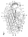
- FIG. 1 is the contour of the block-shaped receiving body 6 shows.
- the illustration of the top of the receiving body 6 includes in a first and second valve row X, Y a total of eight valve receiving holes 1, 2, in which electromagnetically actuated intake and exhaust valves are used for a motor vehicle dual-circuit brake system.
- Y is located in a valve receiving holes 1, 2 deeper level in the receiving body 6, a pump receiving bore. 4
- a motor receiving bore 11 extends as shown by the bottom of the receiving body 6 perpendicular to the pump receiving bore 4.
- the bottom of the pump receiving bore 4 directed motor receiving bore 11 not only takes to drive a Pump required in the pump receiving bore 4 electric motor, but also the required for a radial piston pump eccentric or crank drive. With regard to the details explained on the bottom, see the illustration in FIG. 2 directed.
- valve receiving bores 1, 2 and the motor receiving bore 11 are thus axially parallel to each other as blind holes from the top and bottom of the receiving body 6 automatically produced.
- the second located next to the pump receiving bore 4 second Valve Y only picks up the exhaust valves needed to reduce the brake pressure in the wheel brakes.
- This arrangement results in a particularly short pressure medium connection from the outlet valves to the suction-side connection to the pump receiving bore 4 via one of the low-pressure accumulator piston having two memory receiving holes 8, which open transversely to the rows of valves X, Y, in the rear side surface of the receiving body 6 and over Pressure medium channels with the valve receiving holes 2 of the second valve row Y are connected.
- the inlet valves are located exclusively in the valve receiving bores 1 of the first valve row X, which are removed by the second valve row Y from the vertical plane of the receiving body 6, which has the pump receiving bore 4.
- a third valve row Z emerges whose valve receiving bores 3, 10 in an arcuate row arrangement spaced from the first and second valve rows X, Y likewise open like the valve receiving bores 1, 2 of the first and second valve rows X, Y paraxially into the upper side of the receiving body 6 ,
- This third valve series Z ensures a simple functional extension of the designed for blocking pressure control Hydraulic power units for the purpose of Antriebsschlupf- or vehicle dynamics control, including running in the two outer valve receiving bores 3 of the third row Z valve as electrical switching valves, used in basic position closed solenoid valves in the traction or driving dynamic operation, a direct hydraulic connection of the pump suction with the at the Bremsdruckgeberan Whyn B1, B2 connectable tandem master cylinder.
- solenoid valves are circuitry between the leading to the brake pressure transducer terminals B1, B2 and the valve receiving holes 1 of the first valve row X channels.
- These isolation valves take their traction slip or vehicle dynamics control their electromagnetically closed switching position, so that the sucked by the pump via the open changeover valves from the reservoir of the tandem master cylinder pressure medium can not be fed back to the non-pressurized reservoir via the tandem master cylinder.
- the measures provided for the electrical switching valves valve receiving holes 3 are connected via their lateral surfaces on a pressure medium channel 5, according to FIG. 1 below the valve rows X, Y leads to the brake pressure generator port B1 or B2 of each brake circuit.
- Blockverbohrung provides that in addition to the pump receiving bore 4 a few coaxially aligned noise damping chambers 12 are arranged according to FIG. 1 below the arranged in the first and second rows of valves Y.
- Valve receiving holes 1, 2 open as blind holes from both diametrical sides in the receiving body 6.
- the two noise damping chambers 12 communicate with the pressure side ports of the pump receiving bore 4 and the valve receiving bores 1 of the first valve row X in combination.
- Y Remote from the first and second valve row X, Y is located next to the third row of valves Z further a passage 9 to the power supply between a placed on top of the receiving body 6 controller and arranged on the underside of the receiving body 6 electric motor for driving the pump to ensure.
- Threaded holes 13 are provided for fastening a top of the receiving body 6 closing lid, which includes an electronic control unit.
- the lid is sealed along its contact surface to be placed on the receiving body 6, for which purpose preferably a peripheral seal is suitable, which is either molded onto the lid or held in a lid groove.
- the front side of the receiving body 6 accommodates all wheel brake connections R1, R2, R3, R4, which can be connected to the front and rear wheel brakes of a motor vehicle.
- These wheel brake connections R1, R2, R3, R4 are connected via short pressure medium channels to the valve receiving bores 1 of the first valve row X and via the intake valves opened therein in the basic position to the brake pressure generator connections B1, B2, which likewise open space-wise at the front of the receiving body 6.
- each valve receiving bore 1, 2 of the first and second valve rows X, Y Pressure medium channel which continues via a connecting channel 14 in the open position of the associated outlet valve respectively below the pump receiving bore 4 to the storage receiving bore 8.
- FIG. 2 shows the receiving body 6 after FIG. 1 Well visible in this case is the motor mounting hole 11, which penetrates for receiving an eccentric drive provided for a radial piston pump pump mounting hole 4 at half the length.
- FIG. 2 shows that in the open position of each located in the second row of valves Y, electromagnetically controlled outlet valve in the valve receiving bore 2 of the second valve row Y pending pressure medium passes into the formed as a collecting channel horizontal pressure medium channel that leads for each brake circuit via the connecting channel 14 to the storage receiving bore 8 ,
- Each of the two memory receiving holes 8 arranged in parallel has, as shown, a return channel running horizontally in the receiving body 6, with a pressure retention valve 15, which opens into the suction-side region of the pump receiving bore 4.
- FIG. 1 It is apparent from the compact design of the hydraulic unit which is provided for receiving the electrical switching valve valve receiving bore 3 respectively in the longitudinal plane of the pump receiving bore 4, so after FIG. 1 the valve receiving bore 3 is integrated directly above the pump receiving bore 4 in the receiving body 6, which results in a low-resistance suction for the pump.
- valve receiving bore 3 is thus within the longitudinal plane of the pump receiving bore 4 at the shortest distance with the suction-side region of the pump bore 3 in connection, while the lateral surface of the valve provided for receiving the electrical changeover valve receiving bore 3 via a simple to manufacture pressure medium channel 5 each with the associated brake pressure generator port B1 , B2, which opens transversely to the three valve rows X, Y, Z in the receiving body 6.
- valve receiving bore 3 By the arrangement of the valve receiving bore 3 in register with the pump receiving bore 4 remains in accordance Fig. 1 above the storage receiving bore 8, a sufficiently large space in the receiving body 6 for arranging a suitable pressure for the brake pressure monitoring pressure sensor, which is thus advantageously secured in a above the storage bore 8 arranged Drucksensorareabohrung 7. How out FIG.
- the pressure sensor receiving bore 7 can thus be arranged in an extremely compact manner at a radial distance from the storage receiving bore 8 in its longitudinal plane, the pressure sensor receiving bore 7 being connected to the brake pressure transducer connection B1, B2 for the purpose of an unproblematic hydraulic connection of the pressure sensor receiving bore 7
- the Drucksensorareabohrung 7 is connected by the shortest route to the leading to the brake pressure generator port B1, B2 pressure medium channel 5, which opens into the lateral surface of the valve receiving bore 3, which is provided for the switching valve.
- the provided for receiving the electrical switching valve valve receiving bore 3 is thus advantageously arranged space between the second valve row Y and the Drucksensorareabohrung 7, which opens axially parallel to the valve receiving bores of the three valve rows X, Y, Z in the receiving body 6.
- the presented hydraulic unit is designed in the present example for a motor vehicle dual-circuit brake system, with the features that for individual driving dynamics control on all wheel brakes, the third valve row Z has four valve receiving bores 3, 10 for two separating and two changeover valves, which provided for the two isolation valves Valve receiving bores 10 are arranged between the valve receiving bores 3 provided for the changeover valves, which are offset from the valve row Z in the direction of the pump receiving bore 4 for optimum utilization of the available installation space.
- all four wheel brake connections R1, R2, R3, R4 are arranged in parallel in a row for connecting the hydraulic unit to the wheel brakes, with the special feature that all wheel brake connections are parallel to the two brake pressure generator connections B1, B2 in a side face of the brake brake Receiving body 6 open, which has the brake pressure transducer terminals B1, B2.
- FIG. 2 It can be seen, the circumferential dimension of the block-shaped receiving body 6 due to the previously described arrangement of all mounting holes, pressure fluid channels, wheel and brake connections so far reduce that the inserted into the motor receiving bore 11 electric motor almost covers the entire surface of the receiving body 6, so that the housing of the electric motor can be attached to the illustrated attachment points 16 by caulking at the four outer edges of the receiving body 6 automatically.
Landscapes
- Physics & Mathematics (AREA)
- Electromagnetism (AREA)
- Engineering & Computer Science (AREA)
- Fluid Mechanics (AREA)
- Transportation (AREA)
- Mechanical Engineering (AREA)
- Regulating Braking Force (AREA)
Claims (10)
- Unité hydraulique pour systèmes de freinage à régulation antipatinage,- comprenant un corps de réception (6) qui reçoit des soupapes d'admission et d'évacuation dans plusieurs alésages de réception de soupape (1, 2) d'une première et d'une deuxième rangée de soupapes (X, Y),- comprenant un alésage de réception de pompe (4) disposé dans le corps de réception (6) à l'extérieur par rapport aux deux rangées de soupapes (X, Y), lequel alésage de réception de pompe est orienté transversalement par rapport à la direction dans laquelle les alésages de réception de soupape (1, 2) débouchent dans le corps de réception (6),- comprenant un alésage de réception de moteur (11) disposé à l'extérieur par rapport aux deux rangées de soupapes (X, Y) dans le corps de réception (6), lequel alésage de réception de moteur est orienté perpendiculairement à l'alésage de réception de pompe (4),- comprenant un alésage de réception d'accumulateur (8) débouchant à l'extérieur par rapport aux deux rangées de soupapes (X, Y) dans le corps de réception (6),- comprenant plusieurs conduits de fluide sous pression (5, 14) reliant les alésages de réception de soupape, de pompe et d'accumulateur (1, 2, 4, 8), lesquels conduits de fluide sous pression sont à même de réaliser une liaison hydraulique entre des raccords de générateur de pression de frein (B1, B2) et plusieurs raccords de frein de roue (R1, R2, R3, R4)- et comprenant plusieurs alésages de réception de soupape (3), disposés dans une troisième rangée de soupapes (Z), pour la réception d'une soupape de séparation et d'une soupape d'inversion électrique qui est disposée entre l'un des raccords de générateur de pression de frein (B1, B2) et le côté aspiration d'une pompe, l'alésage de réception de soupape (3) prévu pour la réception de la soupape d'inversion électrique étant disposé dans le plan de l'alésage de réception de pompe (4),
caractérisée en ce que l'alésage de réception de soupape (3) prévu pour la réception de la soupape d'inversion électrique est disposé entre la deuxième rangée de soupapes (Y) et un alésage de réception de capteur de pression (7) qui débouche dans le corps de réception (6) avec son axe parallèle à ceux des alésages de réception de soupape des trois rangées de soupapes (X, Y, Z), et en ce que l'alésage de réception de capteur de pression (7) est disposé en affleurement dans le plan des alésages de réception de soupape (1, 2, 3) qui se trouvent à l'extrémité extérieure respective des rangées de soupapes (X, Y, Z) dans les trois rangées de soupapes (X, Y, Z). - Unité hydraulique selon la revendication 1, caractérisée en ce que le fond de l'alésage de réception de soupape (3), prévu pour la réception de la soupape d'inversion électrique, à l'intérieur du plan de l'alésage de réception de pompe (4) comprend une liaison hydraulique à la région côté aspiration de l'alésage de réception de pompe (3).
- Unité hydraulique selon la revendication 1 ou 2, caractérisée en ce que la surface extérieure de l'alésage de réception de soupape (3) prévu pour la réception de la soupape d'inversion électrique est reliée, par le biais d'un conduit de fluide sous pression (5), au raccord de générateur de pression de frein (B1, B2) qui débouche transversalement par rapport aux trois rangées de soupapes (X, Y, Z) dans le corps de réception (6).
- Unité hydraulique selon la revendication 1, caractérisée en ce que l'alésage de réception de capteur de pression (7) est disposé au-dessus de l'alésage de réception d'accumulateur de manière espacée radialement par rapport à l'alésage de réception d'accumulateur (8).
- Unité hydraulique selon la revendication 1, caractérisée en ce que l'alésage de réception de capteur de pression (7) est relié au conduit de fluide sous pression (5) menant jusqu'au raccord de générateur de pression de frein (B1, B2), lequel conduit de fluide sous pression débouche dans la surface extérieure de l'alésage de réception de soupape (3) qui est prévu pour la soupape d'inversion.
- Unité hydraulique selon la revendication 1, caractérisée en ce qu'un passage (9) est prévu à proximité immédiate de l'alésage de réception d'accumulateur et de capteur de pression (8, 7) pour la réception d'un connecteur électrique dans le corps de réception (6), lequel passage est disposé à proximité immédiate de l'alésage de réception de soupape (10) qui est prévu pour la soupape de séparation.
- Unité hydraulique selon la revendication 1, caractérisée en ce que la première rangée de soupapes (X) est disposée directement entre la deuxième rangée de soupapes (Y) et les raccords de générateur de pression de frein et de frein de roue (R1, R2, R3, R4, B1, B2), la première rangée de soupapes (X) recevant exclusivement les soupapes d'admission et la deuxième rangée de soupapes (Y) recevant exclusivement les soupapes d'évacuation.
- Unité hydraulique selon la revendication 1, caractérisée en ce que la deuxième rangée de soupapes (Y) est disposée directement entre la première rangée de soupapes (X) et les alésages de réception de soupape (3) de la troisième rangée de soupapes (Z) qui comprennent la soupape d'inversion électrique et la soupape de séparation.
- Unité hydraulique pour un système de freinage à deux circuits de véhicule automobile selon l'une quelconque des revendications précédentes, caractérisée en ce que la troisième rangée de soupapes (Z) comprend quatre alésages de réception de soupape (3, 10) pour deux soupapes de séparation ainsi que pour deux soupapes d'inversion en vue d'une régulation individuelle de la dynamique de conduite au niveau de tous les freins de roue, les alésages de réception de soupape (10) prévus pour les deux soupapes de séparation étant disposés entre les alésages de réception de soupape (3) prévus pour les soupapes d'inversion, lesquels alésages de réception de soupape (3) sont décalés par rapport à la rangée de soupapes (Z) en direction de l'alésage de pompe (4).
- Unité hydraulique pour un système de freinage à deux circuits de véhicule automobile selon la revendication 10, caractérisée en ce que quatre raccords de frein de roue (R1, R2, R3, R4) sont disposés parallèlement en une rangée pour le raccordement de l'unité hydraulique aux freins de roue, lesquels raccords de frein de roue débouchent dans une surface latérale du corps de réception (6) parallèlement aux deux raccords de générateur de pression de frein (B1, B2), laquelle surface latérale comprend les raccords de générateur de pression de frein (B1, B2).
Applications Claiming Priority (3)
| Application Number | Priority Date | Filing Date | Title |
|---|---|---|---|
| DE102007027236 | 2007-06-13 | ||
| DE102007053174A DE102007053174A1 (de) | 2007-06-13 | 2007-11-08 | Hydraulikaggregat für schlupfgeregelte Bremsanlagen |
| PCT/EP2008/056434 WO2008151919A1 (fr) | 2007-06-13 | 2008-05-27 | Unité hydraulique pour systèmes de freinage à dispositif anti-patinage |
Publications (2)
| Publication Number | Publication Date |
|---|---|
| EP2158113A1 EP2158113A1 (fr) | 2010-03-03 |
| EP2158113B1 true EP2158113B1 (fr) | 2013-08-14 |
Family
ID=40030889
Family Applications (1)
| Application Number | Title | Priority Date | Filing Date |
|---|---|---|---|
| EP08760033.4A Active EP2158113B1 (fr) | 2007-06-13 | 2008-05-27 | Unité hydraulique pour systèmes de freinage à dispositif anti-patinage |
Country Status (3)
| Country | Link |
|---|---|
| EP (1) | EP2158113B1 (fr) |
| DE (1) | DE102007053174A1 (fr) |
| WO (1) | WO2008151919A1 (fr) |
Families Citing this family (1)
| Publication number | Priority date | Publication date | Assignee | Title |
|---|---|---|---|---|
| DE102011089915A1 (de) | 2011-12-27 | 2013-06-27 | Robert Bosch Gmbh | Pumpengehäuse eines Kraftfahrzeug-Hydroaggregats mit einem Rad-Drucksensoranschluss |
Family Cites Families (8)
| Publication number | Priority date | Publication date | Assignee | Title |
|---|---|---|---|---|
| US6398315B1 (en) | 1997-11-14 | 2002-06-04 | Continental Teves Ag & Co. Ohg | Hydraulic unit for slip-controlled brake systems |
| DE10237163B4 (de) * | 2002-08-14 | 2012-12-20 | Robert Bosch Gmbh | Hydraulikaggregat für eine Fahrzeugbremsanlage |
| DE10245068A1 (de) * | 2002-09-27 | 2004-04-08 | Continental Teves Ag & Co. Ohg | Hydraulikaggregat für schlupfgeregelte Bremsanlagen |
| WO2004048173A2 (fr) * | 2002-11-22 | 2004-06-10 | Continental Teves Ag & Co. Ohg | Groupe hydraulique, en particulier pour systemes de freinage a regulation anti-patinage |
| DE10302681B3 (de) * | 2003-01-24 | 2004-08-12 | Robert Bosch Gmbh | Hydraulikaggregat |
| DE10339882A1 (de) * | 2003-06-26 | 2005-01-13 | Continental Teves Ag & Co. Ohg | Hydraulikaggregat für schlupfgeregelte Bremsanlagen |
| WO2004113142A1 (fr) * | 2003-06-26 | 2004-12-29 | Continental Teves Ag & Co. Ohg | Unite hydraulique pour systemes de freinage a regulation antipatinage |
| JP4446919B2 (ja) * | 2005-04-01 | 2010-04-07 | 日信工業株式会社 | 車両用ブレーキ液圧制御装置 |
-
2007
- 2007-11-08 DE DE102007053174A patent/DE102007053174A1/de not_active Withdrawn
-
2008
- 2008-05-27 EP EP08760033.4A patent/EP2158113B1/fr active Active
- 2008-05-27 WO PCT/EP2008/056434 patent/WO2008151919A1/fr not_active Ceased
Also Published As
| Publication number | Publication date |
|---|---|
| WO2008151919A1 (fr) | 2008-12-18 |
| DE102007053174A1 (de) | 2008-12-24 |
| EP2158113A1 (fr) | 2010-03-03 |
Similar Documents
| Publication | Publication Date | Title |
|---|---|---|
| EP2279106B1 (fr) | Groupe hydraulique | |
| EP1545951B1 (fr) | Groupe hydraulique pour systemes de freinage a regulation de glissement | |
| DE102006059924B4 (de) | Hydraulikblock eines Hydroaggregates und Hydroaggregat mit einem solchen Hydraulikblock | |
| EP4263302B1 (fr) | Bloc hydraulique parallélépipédique pour un groupe hydraulique d'une régulation de pression de freinage d'un système de freinage hydraulique de véhicule | |
| WO1999025594A1 (fr) | Groupe hydraulique destine a des systemes de freinage dotes d'un systeme antiblocage des roues | |
| EP3592616A1 (fr) | Bloc hydraulique pour un groupe hydraulique d'une régulation antipatinage d'un système de freinage hydraulique d'un véhicule | |
| DE102008029536A1 (de) | Hydraulikaggregat | |
| DE102014207549A1 (de) | Pumpengehäuseanordnung eines Hydraulikaggregats einer Fahrzeugbremsanlage | |
| DE10237163B4 (de) | Hydraulikaggregat für eine Fahrzeugbremsanlage | |
| DE102020202048A1 (de) | Hydraulikblock für ein Hydraulikaggregat einer hydraulischen Fremdkraft-Fahrzeugbremsanlage | |
| DE102009027827A1 (de) | Pumpengehäuse eines Kraftfahrzeug-Hydroaggregats mit mindestens einer Hauptzylinderanschlussöffnung | |
| WO2012072319A1 (fr) | Carter de pompe pour unité hydraulique d'un véhicule à moteur, et son utilisation | |
| DE19805843A1 (de) | Hydraulikaggregat für schlupfgeregelte Bremsanlagen | |
| EP1641666B1 (fr) | Unite hydraulique pour systemes de freinage a regulation antipatinage | |
| WO2001000471A1 (fr) | Groupe hydraulique | |
| EP3509919A1 (fr) | Bloc hydraulique pour un groupe hydraulique d'une régulation antipatinage d'un système de freinage hydraulique d'un véhicule | |
| DE102005024979A1 (de) | Hydraulikaggregat | |
| WO2002042134A1 (fr) | Unite hydraulique pour systemes de freinage a regulation antipatinage | |
| WO2007128616A1 (fr) | Dispositif de freinage hydraulique | |
| EP1802502B1 (fr) | Systeme de freinage de motocyclette | |
| EP2158113B1 (fr) | Unité hydraulique pour systèmes de freinage à dispositif anti-patinage | |
| WO2002053435A1 (fr) | Unite hydraulique pour systemes de freinage anti-patinage | |
| DE19808626B4 (de) | Elektrohydraulisches Aggregat zur Druckregelung in Kraftfahrzeugbremsanlagen | |
| DE102009019802B4 (de) | Bremsaggregat | |
| DE102016208365A1 (de) | Hydraulikaggregat für eine bremsdruckgeregelte Fahrzeugbremsanlage |
Legal Events
| Date | Code | Title | Description |
|---|---|---|---|
| PUAI | Public reference made under article 153(3) epc to a published international application that has entered the european phase |
Free format text: ORIGINAL CODE: 0009012 |
|
| 17P | Request for examination filed |
Effective date: 20100113 |
|
| AK | Designated contracting states |
Kind code of ref document: A1 Designated state(s): AT BE BG CH CY CZ DE DK EE ES FI FR GB GR HR HU IE IS IT LI LT LU LV MC MT NL NO PL PT RO SE SI SK TR |
|
| AX | Request for extension of the european patent |
Extension state: AL BA MK RS |
|
| DAX | Request for extension of the european patent (deleted) | ||
| 17Q | First examination report despatched |
Effective date: 20101126 |
|
| GRAP | Despatch of communication of intention to grant a patent |
Free format text: ORIGINAL CODE: EPIDOSNIGR1 |
|
| INTG | Intention to grant announced |
Effective date: 20130415 |
|
| GRAS | Grant fee paid |
Free format text: ORIGINAL CODE: EPIDOSNIGR3 |
|
| GRAA | (expected) grant |
Free format text: ORIGINAL CODE: 0009210 |
|
| AK | Designated contracting states |
Kind code of ref document: B1 Designated state(s): AT BE BG CH CY CZ DE DK EE ES FI FR GB GR HR HU IE IS IT LI LT LU LV MC MT NL NO PL PT RO SE SI SK TR |
|
| REG | Reference to a national code |
Ref country code: GB Ref legal event code: FG4D Free format text: NOT ENGLISH |
|
| REG | Reference to a national code |
Ref country code: AT Ref legal event code: REF Ref document number: 626616 Country of ref document: AT Kind code of ref document: T Effective date: 20130815 Ref country code: CH Ref legal event code: EP |
|
| REG | Reference to a national code |
Ref country code: IE Ref legal event code: FG4D Free format text: LANGUAGE OF EP DOCUMENT: GERMAN |
|
| REG | Reference to a national code |
Ref country code: DE Ref legal event code: R096 Ref document number: 502008010484 Country of ref document: DE Effective date: 20131010 |
|
| REG | Reference to a national code |
Ref country code: NL Ref legal event code: VDEP Effective date: 20130814 |
|
| REG | Reference to a national code |
Ref country code: LT Ref legal event code: MG4D |
|
| PG25 | Lapsed in a contracting state [announced via postgrant information from national office to epo] |
Ref country code: SE Free format text: LAPSE BECAUSE OF FAILURE TO SUBMIT A TRANSLATION OF THE DESCRIPTION OR TO PAY THE FEE WITHIN THE PRESCRIBED TIME-LIMIT Effective date: 20130814 Ref country code: HR Free format text: LAPSE BECAUSE OF FAILURE TO SUBMIT A TRANSLATION OF THE DESCRIPTION OR TO PAY THE FEE WITHIN THE PRESCRIBED TIME-LIMIT Effective date: 20130814 Ref country code: PT Free format text: LAPSE BECAUSE OF FAILURE TO SUBMIT A TRANSLATION OF THE DESCRIPTION OR TO PAY THE FEE WITHIN THE PRESCRIBED TIME-LIMIT Effective date: 20131216 Ref country code: NO Free format text: LAPSE BECAUSE OF FAILURE TO SUBMIT A TRANSLATION OF THE DESCRIPTION OR TO PAY THE FEE WITHIN THE PRESCRIBED TIME-LIMIT Effective date: 20131114 Ref country code: LT Free format text: LAPSE BECAUSE OF FAILURE TO SUBMIT A TRANSLATION OF THE DESCRIPTION OR TO PAY THE FEE WITHIN THE PRESCRIBED TIME-LIMIT Effective date: 20130814 Ref country code: CY Free format text: LAPSE BECAUSE OF FAILURE TO SUBMIT A TRANSLATION OF THE DESCRIPTION OR TO PAY THE FEE WITHIN THE PRESCRIBED TIME-LIMIT Effective date: 20130821 Ref country code: IS Free format text: LAPSE BECAUSE OF FAILURE TO SUBMIT A TRANSLATION OF THE DESCRIPTION OR TO PAY THE FEE WITHIN THE PRESCRIBED TIME-LIMIT Effective date: 20131214 |
|
| PG25 | Lapsed in a contracting state [announced via postgrant information from national office to epo] |
Ref country code: GR Free format text: LAPSE BECAUSE OF FAILURE TO SUBMIT A TRANSLATION OF THE DESCRIPTION OR TO PAY THE FEE WITHIN THE PRESCRIBED TIME-LIMIT Effective date: 20131115 Ref country code: SI Free format text: LAPSE BECAUSE OF FAILURE TO SUBMIT A TRANSLATION OF THE DESCRIPTION OR TO PAY THE FEE WITHIN THE PRESCRIBED TIME-LIMIT Effective date: 20130814 Ref country code: PL Free format text: LAPSE BECAUSE OF FAILURE TO SUBMIT A TRANSLATION OF THE DESCRIPTION OR TO PAY THE FEE WITHIN THE PRESCRIBED TIME-LIMIT Effective date: 20130814 Ref country code: LV Free format text: LAPSE BECAUSE OF FAILURE TO SUBMIT A TRANSLATION OF THE DESCRIPTION OR TO PAY THE FEE WITHIN THE PRESCRIBED TIME-LIMIT Effective date: 20130814 Ref country code: FI Free format text: LAPSE BECAUSE OF FAILURE TO SUBMIT A TRANSLATION OF THE DESCRIPTION OR TO PAY THE FEE WITHIN THE PRESCRIBED TIME-LIMIT Effective date: 20130814 |
|
| PG25 | Lapsed in a contracting state [announced via postgrant information from national office to epo] |
Ref country code: CY Free format text: LAPSE BECAUSE OF FAILURE TO SUBMIT A TRANSLATION OF THE DESCRIPTION OR TO PAY THE FEE WITHIN THE PRESCRIBED TIME-LIMIT Effective date: 20130814 |
|
| PG25 | Lapsed in a contracting state [announced via postgrant information from national office to epo] |
Ref country code: RO Free format text: LAPSE BECAUSE OF FAILURE TO SUBMIT A TRANSLATION OF THE DESCRIPTION OR TO PAY THE FEE WITHIN THE PRESCRIBED TIME-LIMIT Effective date: 20130814 Ref country code: EE Free format text: LAPSE BECAUSE OF FAILURE TO SUBMIT A TRANSLATION OF THE DESCRIPTION OR TO PAY THE FEE WITHIN THE PRESCRIBED TIME-LIMIT Effective date: 20130814 Ref country code: SK Free format text: LAPSE BECAUSE OF FAILURE TO SUBMIT A TRANSLATION OF THE DESCRIPTION OR TO PAY THE FEE WITHIN THE PRESCRIBED TIME-LIMIT Effective date: 20130814 Ref country code: NL Free format text: LAPSE BECAUSE OF FAILURE TO SUBMIT A TRANSLATION OF THE DESCRIPTION OR TO PAY THE FEE WITHIN THE PRESCRIBED TIME-LIMIT Effective date: 20130814 Ref country code: DK Free format text: LAPSE BECAUSE OF FAILURE TO SUBMIT A TRANSLATION OF THE DESCRIPTION OR TO PAY THE FEE WITHIN THE PRESCRIBED TIME-LIMIT Effective date: 20130814 Ref country code: CZ Free format text: LAPSE BECAUSE OF FAILURE TO SUBMIT A TRANSLATION OF THE DESCRIPTION OR TO PAY THE FEE WITHIN THE PRESCRIBED TIME-LIMIT Effective date: 20130814 |
|
| PG25 | Lapsed in a contracting state [announced via postgrant information from national office to epo] |
Ref country code: ES Free format text: LAPSE BECAUSE OF FAILURE TO SUBMIT A TRANSLATION OF THE DESCRIPTION OR TO PAY THE FEE WITHIN THE PRESCRIBED TIME-LIMIT Effective date: 20130814 Ref country code: IT Free format text: LAPSE BECAUSE OF FAILURE TO SUBMIT A TRANSLATION OF THE DESCRIPTION OR TO PAY THE FEE WITHIN THE PRESCRIBED TIME-LIMIT Effective date: 20130814 |
|
| PLBE | No opposition filed within time limit |
Free format text: ORIGINAL CODE: 0009261 |
|
| STAA | Information on the status of an ep patent application or granted ep patent |
Free format text: STATUS: NO OPPOSITION FILED WITHIN TIME LIMIT |
|
| 26N | No opposition filed |
Effective date: 20140515 |
|
| REG | Reference to a national code |
Ref country code: DE Ref legal event code: R097 Ref document number: 502008010484 Country of ref document: DE Effective date: 20140515 |
|
| PG25 | Lapsed in a contracting state [announced via postgrant information from national office to epo] |
Ref country code: LU Free format text: LAPSE BECAUSE OF FAILURE TO SUBMIT A TRANSLATION OF THE DESCRIPTION OR TO PAY THE FEE WITHIN THE PRESCRIBED TIME-LIMIT Effective date: 20140527 |
|
| REG | Reference to a national code |
Ref country code: CH Ref legal event code: PL |
|
| GBPC | Gb: european patent ceased through non-payment of renewal fee |
Effective date: 20140527 |
|
| PG25 | Lapsed in a contracting state [announced via postgrant information from national office to epo] |
Ref country code: LI Free format text: LAPSE BECAUSE OF NON-PAYMENT OF DUE FEES Effective date: 20140531 Ref country code: MC Free format text: LAPSE BECAUSE OF FAILURE TO SUBMIT A TRANSLATION OF THE DESCRIPTION OR TO PAY THE FEE WITHIN THE PRESCRIBED TIME-LIMIT Effective date: 20130814 Ref country code: CH Free format text: LAPSE BECAUSE OF NON-PAYMENT OF DUE FEES Effective date: 20140531 |
|
| REG | Reference to a national code |
Ref country code: IE Ref legal event code: MM4A |
|
| PG25 | Lapsed in a contracting state [announced via postgrant information from national office to epo] |
Ref country code: IE Free format text: LAPSE BECAUSE OF NON-PAYMENT OF DUE FEES Effective date: 20140527 |
|
| PG25 | Lapsed in a contracting state [announced via postgrant information from national office to epo] |
Ref country code: GB Free format text: LAPSE BECAUSE OF NON-PAYMENT OF DUE FEES Effective date: 20140527 |
|
| REG | Reference to a national code |
Ref country code: AT Ref legal event code: MM01 Ref document number: 626616 Country of ref document: AT Kind code of ref document: T Effective date: 20140527 |
|
| PG25 | Lapsed in a contracting state [announced via postgrant information from national office to epo] |
Ref country code: AT Free format text: LAPSE BECAUSE OF NON-PAYMENT OF DUE FEES Effective date: 20140527 |
|
| PG25 | Lapsed in a contracting state [announced via postgrant information from national office to epo] |
Ref country code: MT Free format text: LAPSE BECAUSE OF FAILURE TO SUBMIT A TRANSLATION OF THE DESCRIPTION OR TO PAY THE FEE WITHIN THE PRESCRIBED TIME-LIMIT Effective date: 20130814 |
|
| REG | Reference to a national code |
Ref country code: FR Ref legal event code: PLFP Year of fee payment: 9 |
|
| PG25 | Lapsed in a contracting state [announced via postgrant information from national office to epo] |
Ref country code: BG Free format text: LAPSE BECAUSE OF FAILURE TO SUBMIT A TRANSLATION OF THE DESCRIPTION OR TO PAY THE FEE WITHIN THE PRESCRIBED TIME-LIMIT Effective date: 20130814 |
|
| PG25 | Lapsed in a contracting state [announced via postgrant information from national office to epo] |
Ref country code: TR Free format text: LAPSE BECAUSE OF FAILURE TO SUBMIT A TRANSLATION OF THE DESCRIPTION OR TO PAY THE FEE WITHIN THE PRESCRIBED TIME-LIMIT Effective date: 20130814 Ref country code: BE Free format text: LAPSE BECAUSE OF FAILURE TO SUBMIT A TRANSLATION OF THE DESCRIPTION OR TO PAY THE FEE WITHIN THE PRESCRIBED TIME-LIMIT Effective date: 20140531 Ref country code: HU Free format text: LAPSE BECAUSE OF FAILURE TO SUBMIT A TRANSLATION OF THE DESCRIPTION OR TO PAY THE FEE WITHIN THE PRESCRIBED TIME-LIMIT; INVALID AB INITIO Effective date: 20080527 |
|
| REG | Reference to a national code |
Ref country code: FR Ref legal event code: PLFP Year of fee payment: 10 |
|
| REG | Reference to a national code |
Ref country code: FR Ref legal event code: PLFP Year of fee payment: 11 |
|
| REG | Reference to a national code |
Ref country code: DE Ref legal event code: R084 Ref document number: 502008010484 Country of ref document: DE |
|
| PGFP | Annual fee paid to national office [announced via postgrant information from national office to epo] |
Ref country code: DE Payment date: 20220531 Year of fee payment: 15 |
|
| REG | Reference to a national code |
Ref country code: DE Ref legal event code: R081 Ref document number: 502008010484 Country of ref document: DE Owner name: CONTINENTAL AUTOMOTIVE TECHNOLOGIES GMBH, DE Free format text: FORMER OWNER: CONTINENTAL TEVES AG & CO. OHG, 60488 FRANKFURT, DE |
|
| REG | Reference to a national code |
Ref country code: DE Ref legal event code: R119 Ref document number: 502008010484 Country of ref document: DE |
|
| PG25 | Lapsed in a contracting state [announced via postgrant information from national office to epo] |
Ref country code: DE Free format text: LAPSE BECAUSE OF NON-PAYMENT OF DUE FEES Effective date: 20231201 |
|
| PGFP | Annual fee paid to national office [announced via postgrant information from national office to epo] |
Ref country code: FR Payment date: 20250528 Year of fee payment: 18 |