EP1545951B1 - Groupe hydraulique pour systemes de freinage a regulation de glissement - Google Patents
Groupe hydraulique pour systemes de freinage a regulation de glissement Download PDFInfo
- Publication number
- EP1545951B1 EP1545951B1 EP03757805A EP03757805A EP1545951B1 EP 1545951 B1 EP1545951 B1 EP 1545951B1 EP 03757805 A EP03757805 A EP 03757805A EP 03757805 A EP03757805 A EP 03757805A EP 1545951 B1 EP1545951 B1 EP 1545951B1
- Authority
- EP
- European Patent Office
- Prior art keywords
- valve
- accommodating
- bore
- bores
- pump
- Prior art date
- Legal status (The legal status is an assumption and is not a legal conclusion. Google has not performed a legal analysis and makes no representation as to the accuracy of the status listed.)
- Expired - Lifetime
Links
- 239000012530 fluid Substances 0.000 claims description 7
- 230000004308 accommodation Effects 0.000 claims 3
- 238000005086 pumping Methods 0.000 abstract 2
- 238000006073 displacement reaction Methods 0.000 description 7
- 238000002955 isolation Methods 0.000 description 4
- 230000008901 benefit Effects 0.000 description 3
- 238000010586 diagram Methods 0.000 description 3
- 239000000463 material Substances 0.000 description 2
- 230000009471 action Effects 0.000 description 1
- 230000004913 activation Effects 0.000 description 1
- 230000000712 assembly Effects 0.000 description 1
- 238000000429 assembly Methods 0.000 description 1
- 230000006399 behavior Effects 0.000 description 1
- 238000005352 clarification Methods 0.000 description 1
- 238000011109 contamination Methods 0.000 description 1
- 230000007547 defect Effects 0.000 description 1
- 238000001514 detection method Methods 0.000 description 1
- 230000006870 function Effects 0.000 description 1
- 230000010354 integration Effects 0.000 description 1
- 238000000034 method Methods 0.000 description 1
- 230000010349 pulsation Effects 0.000 description 1
- 230000004044 response Effects 0.000 description 1
- 238000009423 ventilation Methods 0.000 description 1
- 238000013022 venting Methods 0.000 description 1
Images


Classifications
-
- B—PERFORMING OPERATIONS; TRANSPORTING
- B60—VEHICLES IN GENERAL
- B60T—VEHICLE BRAKE CONTROL SYSTEMS OR PARTS THEREOF; BRAKE CONTROL SYSTEMS OR PARTS THEREOF, IN GENERAL; ARRANGEMENT OF BRAKING ELEMENTS ON VEHICLES IN GENERAL; PORTABLE DEVICES FOR PREVENTING UNWANTED MOVEMENT OF VEHICLES; VEHICLE MODIFICATIONS TO FACILITATE COOLING OF BRAKES
- B60T8/00—Arrangements for adjusting wheel-braking force to meet varying vehicular or ground-surface conditions, e.g. limiting or varying distribution of braking force
- B60T8/32—Arrangements for adjusting wheel-braking force to meet varying vehicular or ground-surface conditions, e.g. limiting or varying distribution of braking force responsive to a speed condition, e.g. acceleration or deceleration
- B60T8/34—Arrangements for adjusting wheel-braking force to meet varying vehicular or ground-surface conditions, e.g. limiting or varying distribution of braking force responsive to a speed condition, e.g. acceleration or deceleration having a fluid pressure regulator responsive to a speed condition
- B60T8/40—Arrangements for adjusting wheel-braking force to meet varying vehicular or ground-surface conditions, e.g. limiting or varying distribution of braking force responsive to a speed condition, e.g. acceleration or deceleration having a fluid pressure regulator responsive to a speed condition comprising an additional fluid circuit including fluid pressurising means for modifying the pressure of the braking fluid, e.g. including wheel driven pumps for detecting a speed condition, or pumps which are controlled by means independent of the braking system
- B60T8/4072—Systems in which a driver input signal is used as a control signal for the additional fluid circuit which is normally used for braking
- B60T8/4081—Systems with stroke simulating devices for driver input
-
- B—PERFORMING OPERATIONS; TRANSPORTING
- B60—VEHICLES IN GENERAL
- B60T—VEHICLE BRAKE CONTROL SYSTEMS OR PARTS THEREOF; BRAKE CONTROL SYSTEMS OR PARTS THEREOF, IN GENERAL; ARRANGEMENT OF BRAKING ELEMENTS ON VEHICLES IN GENERAL; PORTABLE DEVICES FOR PREVENTING UNWANTED MOVEMENT OF VEHICLES; VEHICLE MODIFICATIONS TO FACILITATE COOLING OF BRAKES
- B60T8/00—Arrangements for adjusting wheel-braking force to meet varying vehicular or ground-surface conditions, e.g. limiting or varying distribution of braking force
- B60T8/32—Arrangements for adjusting wheel-braking force to meet varying vehicular or ground-surface conditions, e.g. limiting or varying distribution of braking force responsive to a speed condition, e.g. acceleration or deceleration
- B60T8/34—Arrangements for adjusting wheel-braking force to meet varying vehicular or ground-surface conditions, e.g. limiting or varying distribution of braking force responsive to a speed condition, e.g. acceleration or deceleration having a fluid pressure regulator responsive to a speed condition
- B60T8/36—Arrangements for adjusting wheel-braking force to meet varying vehicular or ground-surface conditions, e.g. limiting or varying distribution of braking force responsive to a speed condition, e.g. acceleration or deceleration having a fluid pressure regulator responsive to a speed condition including a pilot valve responding to an electromagnetic force
- B60T8/3615—Electromagnetic valves specially adapted for anti-lock brake and traction control systems
- B60T8/3675—Electromagnetic valves specially adapted for anti-lock brake and traction control systems integrated in modulator units
- B60T8/368—Electromagnetic valves specially adapted for anti-lock brake and traction control systems integrated in modulator units combined with other mechanical components, e.g. pump units, master cylinders
-
- Y—GENERAL TAGGING OF NEW TECHNOLOGICAL DEVELOPMENTS; GENERAL TAGGING OF CROSS-SECTIONAL TECHNOLOGIES SPANNING OVER SEVERAL SECTIONS OF THE IPC; TECHNICAL SUBJECTS COVERED BY FORMER USPC CROSS-REFERENCE ART COLLECTIONS [XRACs] AND DIGESTS
- Y10—TECHNICAL SUBJECTS COVERED BY FORMER USPC
- Y10S—TECHNICAL SUBJECTS COVERED BY FORMER USPC CROSS-REFERENCE ART COLLECTIONS [XRACs] AND DIGESTS
- Y10S303/00—Fluid-pressure and analogous brake systems
- Y10S303/10—Valve block integrating pump, valves, solenoid, accumulator
Definitions
- DE 198 05 843 A1 discloses a hydraulic unit for a slip-controlled brake system, in the receiving body of which valve receiving bores are introduced in a first and second valve row for receiving intake and exhaust valves are. At a distance from the two valve rows, a third valve row is arranged in the block-shaped receiving body, which receives so-called special valves. Between the pairs of valve rows and the third row of valves, a pump receiving bore for a pump drive element is provided in the receiving body. Receiving bores for two conveyors extend parallel to the rows of valves and at right angles to the direction of the opening of the valve receiving bores into the receiving body.
- the known unit is not suitable for use within an electro-hydraulic brake system, in which the driver expresses only a braking request, which is effectively implemented by-wire of the brake system. Because in such systems, the pump is used to charge a high-pressure accumulator, which is used to increase the pressure in wheel brakes. Starting from the high-pressure volume to be provided, a pump is required which not only has a high pressure medium pressure, but also provides a high pressure medium volume flow with low operating noise.
- a first receiving bore for a first conveying device of the pump is passed between valve receiving bores of the first and second valve row, and a second and third receiving bore for receiving second and third conveying devices of the pump is passed between valve receiving bores of the third valve row.
- FIG. 1 circuit diagram of an electro-hydraulic brake system with so-called black / white division comprises a pedal-operated tandem master cylinder 1 with simulator means, at the hydraulic brake circuits 2.3 in the usual way per axis two wheel brakes 4 (VL), 5 (VR ); 6 (HL), 7 (HR) are connected.
- the intermediate hydraulic valves 8, 9, 10, 11 are switched to passage without current.
- 8.9 are separating valves, which separate the master cylinder 1 when energized from the wheel brakes 4 to 7.
- the valves 10, 11 serve to equalize the pressure between the wheel brakes 4, 5, 6, 7 on one axle and can be selectively closed for the purpose of driving stability control intervention or for wheel-specific brake pressure regulation.
- the brake circuits 2,3 are at least in the range of lines leading from the tandem master cylinder 1 to the wheel brakes 4 to 7, interrupted, so that the braking action or the brake pressure curve in the wheel brakes 4 to 7 exclusively sensor-determined in response to electrical signals which are obtained by means of a pedal travel sensor 12 for detecting the actuation of the brake pedal 13 or other brake actuator (SBC, S ensoric B rake C ontrol).
- SBC brake actuator
- the brake system further includes a high pressure accumulator 14, here for example a bellows accumulator, which in the illustrated embodiment with a displacement sensor 15th equipped for determining the storage level, and is used for path detection of a media separating element.
- a high pressure accumulator 14 here for example a bellows accumulator, which in the illustrated embodiment with a displacement sensor 15th equipped for determining the storage level, and is used for path detection of a media separating element.
- the displacement sensor 15 is not absolutely necessary if, for example, a so-called separating piston is provided between the isolation valve 8 and the wheel brake 4, 5.
- This embodiment is expressly included in the total disclosure content.
- the high-pressure accumulator 14 is assigned a pressure sensor 16.
- the pressure defined by the driver is measured in one of the brake circuits 2, 3 by means of a pressure sensor 17. Further pressure sensors 18, 19, 20, 21 measure the actual pressure in the wheel brakes 4, 5, 6, 7. The wheel rotational behavior is detected by means of wheel rotation sensors 22, 23, 24, 25.
- the pressure source essentially comprises the high-pressure accumulator 14 and a pump 30, in particular by electric motor 31 driven piston pump with three conveyors 32,33,34, which connected on the suction side via a respective check valve 35,36,37 and a common suction channel 47 with a pressure chamber of the master cylinder 1 is.
- the proposed 3-piston pump has balanced mass forces in addition to low pulsations, so that a low operating noise occurs.
- each delivery device 32, 33, 34 has check valves 38, 39, 40 (pressure valves) which lead into a common, essentially U-shaped collecting channel 76 provided with a filter which opens into the high-pressure accumulator 14 ( Fig. 6).
- the pressure in the wheel brakes 4 to 7 is metered by appropriate, advantageously proportionally controlled control of the intake valves 26-29.
- outlet valves 41 to 44 are provided, the outputs of which are guided via a return passage 45 to a pressure medium container 46. All within a dashed line in Fig. 1 shown region arranged components and units are located directly on or in a receiving body 48 of a hydraulic unit (HCU) whose details will be described below with reference to Figures 2 to 8.
- HCU hydraulic unit
- the hydraulic unit with assemblies mounted on the receiving body 48 such as electric motor 31, housing 49 for an electronic controller (ECU) and high-pressure accumulator 14, emerges.
- Electric motor 31 and housing 49 are arranged on opposite upper and lower sides of the receiving body 48.
- a connector strip 50 for connection of the ECU with electric motor 31 to a power supply and a vehicle-side bus system is provided laterally next to the receiving body 48 and parallel to an axis of the electric motor 31 pointing.
- the high-pressure accumulator 14 is on a longitudinal side of the receiving body 48 to 90 ° pivoted to a vertical axis u between the electric motor 31 and housing 49 and arranged with respect to the side with the wheel R1-R4, which allows a particularly compact design and a space-optimized bore of the receiving body 48. If the mounting position of the hydraulic unit in the vehicle is selected so that the high-pressure accumulator 14 points vertically downwards, memory (eg due to memory defect) enters the system into the memory receiving bore 58, so that these are easily removed from the receiving body 48 with venting methods can.
- the memory-side displacement sensor 15 is electrically connected to the ECU via a line.
- On a longitudinal side opposite the high-pressure accumulator 14 are hydraulic connections R1-R4 for the wheel brakes 4 to 7, and connections B1, B2 for circuits 2, 3 (pressure chambers) of the master cylinder 1.
- On a motor-side upper side is a return connection R for connecting the pressure medium container 46 provided with the pump-side return passage 45.
- the return channel 45 bifurcates and opens on the one hand by means of a bypass 75 in a basically filled with pressure medium crankcase within the pump receiving bore 53, and on the other hand in a receiving bores 52-52 "'(Auslrawventilaufnahmbohrungen) interconnecting collection channel 73 (Fig. 8) Top is over it
- a suction port S is provided, via which a suction channel 47 of the pump 30 is connected to the pressure medium container 46.
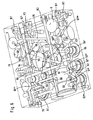
- the receiving body 48 includes in each of a first and in a second row of valves X, Y a total of eight valve receiving bores 51,51 ', 51 ", 51'" (inlet valve receiving bores); 52,52 ', 52 "', 52” '(exhaust valve receiving bores) into which the electromagnetically actuated intake and exhaust valves (26-29, 41-44) can be inserted.
- a pump receiving bore 53 for receiving at least one pump drive element such as an eccentric for driving pump piston.
- the pump receiving bore 53 extends axially parallel to the valve receiving bores (51-51 "', 52-52"'), at least partially serves as a crankcase and receives a, the drive of the pump 30 serving eccentric or crank drive.
- a third row of valves Z also emerges from FIGS. 3-6, which opens into the housing surface of the receiving body 48 next to the pump receiving bore 53 and away from - as well as opposite to - the first and second valve rows X, Y.
- this third valve series Z ensures the possibility of a wheel-specific brake pressure control as well as a traction slip or vehicle dynamics control function.
- the separating valves 8,9 can be used in outer valve receiving bores 54,54 '.
- the pressure compensation valves 10,11 can be used in the two intermediate valve receiving bores 55,55 '.
- the exact arrangement of the valve row Z differs by a trapezoidal shape of the linear arrangement of the other two valve rows X, Y.
- modified arrangement forms are also conceivable for the valve rows X, Y, Z, as long as the series character is maintained at least to a limited extent.
- the arrangement of opening into the receiving body 4 ports B1, B2 of the master cylinder 1 and leading to the wheel brakes ports R1, R2, R3, R4 allows a uniform connection pattern for brake lines on a side surface of the receiving body 48.
- this side surface in the vehicle upwards so that it can be easily accessed for assembly or disassembly.
- receiving bores 56 to 56 are provided, of which the first between valve receiving bores 51 ', 51", 52', 52 "of the first and second valve row X, Y and the second and third receiving bores 56 ', 56 "are passed between valve receiving bores (54, 55; 54', 55 ') of the third valve row Z, so that the available space is used optimally.
- the receiving bore 56 extends transversely to the two valve rows X, Y.
- Adjacent receiving bores 56, 56 ', 56 are each arranged in a V shape and at an identical angle ⁇ of 120 ° to one another.
- each receiving bore 56, 56', 56" has the check valve 35,36,37 (suction valve) for pressure medium ventilation in a displacement chamber. It is understood that each conveyor 32,33,39 may have translationally displaceable displacement piston in a known manner, which are guided directly in the material of the receiving body 48 or in sleeves made of wear-resistant material.
- a row of pressure sensor receiving bores 57, 57 ', 57 “, 57”' are provided at a distance from the third valve row Z, and at least one outer part of the receiving bore 56 ', 56 "extends between a valve receiving bore 54, 54' of the third valve row Z and a pressure sensor receiving bore 57,57 “'. It should not be concealed that optionally further pressure sensor receiving bores for pressure sensors 16, 17 are possible, which serve for pressure sensing in a circuit 2, 3 of the master cylinder 1 or in the high-pressure accumulator 14.
- a memory receiving bore 58 is arranged, on the one hand with the high-pressure accumulator 14 and on the other hand via hydraulic channels and intermediate check valves 38-40 (pressure valves) with the conveyors 32,33,34 connected is. This arrangement makes optimal use of the space available on this site. Because between high-pressure accumulator 13 and 4-4 wheel brakes, a closing valve 74 is provided which is integrated within the memory receiving bore 58 and a screwed into the memory receiving bore 58 connecting piece.
- the storage receiving bore 58 is perpendicular to the extending direction the valve rows X, Y are provided between respectively adjacent valve receiving bores 51 ", 51"', 52 “, 52”'.
- a through-bore 60 is provided between the receiving bores 56 ', 56 ", which can be used to carry out an electrical supply line for the electric motor 31. Further through-bores for carrying further elements, in particular for electrical connection of the displacement sensor 15, are possible. Further, it is conceivable to provide through holes for fastening means to fix the electric motor 31 and the housing 49 of the ECU with the same contact pressure on the receiving body 48.
- FIGS. 5-8 Details of the bore of the receiving body 48 are shown in FIGS. 5-8.
- Fig. 5 illustrates the lockable hydraulic connection of the high-pressure accumulator 14 with the wheel brake ports R1-R4.
- the storage receiving bore 58 is connected by a transverse channel 61 to the valve receiving bores 51-51 "'of the first valve row X.
- the pressure medium passes through a connecting channel 62, 62 ', 62 ", 62 with appropriate valve actuation Balancing channels 63, 64 serve to equalize the pressure between wheel brakes 4, 5, 6, 7 of an axle, as far as the compensating valves 10, 11 (as can be seen from FIG. are open.
- Fig. 7 illustrates the pump suction with a suction port S, which is provided with a small lateral offset to the receiving bore 56 'for the second conveyor 33.
- the suction port S opens into a substantially perpendicular connecting section 68 in two L-shaped line sections 69,70 of which substantially right-angled kinking connectors 71,72 lead into the receiving bores 56 ', 56.
- the conveyor 33 has the smallest suction length while the suction length of the conveyors 32 and 34 is about the same.
- the pressure medium return in the direction of the pressure medium container 46 is shown in FIG. 8.
- the exhaust valves 41-44 are opened.
- a collection passage 73 extending parallel to the valve row Y connects all of the exhaust valve receiving bores 52-52 '''and leads via a return passage 45 to the return port R which is hydraulically connected to the pressure fluid reservoir 46.
- a return filter R is used to advantage As can be seen, extends between the flooded crankcase in the pump receiving bore 53 and the return passage 45, a bypass 75, so that any leakage fluid of the conveying devices 32-34 continue the pressure medium circulation is available. As a result, there is a significant advantage in comparison with systems in which leakage fluid is discharged into a separate reservoir or in the ambient atmosphere, thereby causing a drop in pressure fluid tank level.
Landscapes
- Physics & Mathematics (AREA)
- Engineering & Computer Science (AREA)
- Fluid Mechanics (AREA)
- Transportation (AREA)
- Mechanical Engineering (AREA)
- Electromagnetism (AREA)
- Regulating Braking Force (AREA)
- Valves And Accessory Devices For Braking Systems (AREA)
Abstract
Claims (9)
- Groupe hydraulique pour systèmes de freinage à régulation du patinage,
comportant un corps de réception (48) qui reçoit dans plusieurs trous de réception de soupape (51-51"', 52-52"') d'une première et d'une deuxième rangée de soupapes (X, Y), des soupapes d'admission et d'échappement (26-29 ; 41-44),
comportant d'autres trous de réception de soupape (54, 54', 55, 55') disposés à distance de la première et de la deuxième rangée de soupapes (X, Y), dans une troisième rangée de soupapes (Z),
comportant un trou dé réception de pompe (53) disposé entre la deuxième et la troisième rangée de soupapes (X, Y) pour recevoir au moins un élément d'entraînement de pompe, et
comportant des trous de réception (56, 56', 56") pour recevoir des dispositifs de refoulement (32, 33, 34) d'une pompe (30), et
comportant plusieurs canaux de fluide sous pression reliant les soupapes (26-29 ; 41-44 ; 8-11) ainsi que des freins de roue (4-7), lesquels permettent une liaison hydraulique entre un transmetteur de pression de freinage (1) et les freins de roue (4-7),
caractérisé en ce que
un premier trou de réception (56) pour un premier dispositif de refoulement (32) de la pompe (30) passe entre des trous de réception de soupape (51, 51") de la première et de la deuxième rangée de soupapes (X, Y), et
des deuxièmes et troisièmes trous de réception (56', 56") pour la réception de deuxièmes et de troisièmes dispositifs de refoulement (33, 34) de la pompe (30) passent entre des trous de réception de soupape (54, 55 ; 54', 55') de la troisième rangée de soupapes (Z). - Groupe hydraulique selon la revendication 1, caractérisé en ce que les trous de réception (56, 56', 56") pour des dispositifs de refoulement (32, 33, 34) sont disposés en V suivant un angle (α) les uns par rapport aux autres.
- Groupe hydraulique selon la revendication 2, caractérisé en ce que l'angle (α) entre des trous de réception (56, 56', 56") voisins est identique et est égal à 120°.
- Groupe hydraulique selon la revendication 1, caractérisé en ce qu'il est prévu une rangée de trous de réception de capteur de pression (57, 57', 57", 57"') qui sont disposés à côté de la troisième rangée de soupapes (Z), et en ce que le deuxième et le troisième trous de réception (56', 56") pour des dispositifs de refoulement (33, 34) de la pompe (30) passent entre des trous de réception de soupape (54, 54') de la troisième rangée de soupapes (Z) et entre des trous de réception de capteurs de pression (57, 57"').
- Groupe hydraulique selon la revendication 2, caractérisé en ce qu'il est prévu un trou de réception d'accumulateur (58) parallèle à l'axe du premier trou de réception (56) pour le premier dispositif de refoulement (32), et en ce que le trou de réception d'accumulateur (58) et le premier trou de réception (56) sont disposés sur une surface frontale du corps de réception (48).
- Groupe hydraulique selon la revendication 5, caractérisé en ce que le trou de réception d'accumulateur (58) passe entre des trous de réception de soupape (51", 51''' ; 52", 52"') voisins ainsi que perpendiculairement aux rangées de soupapes (X, Y).
- Groupe hydraulique selon la revendication 1, caractérisé en ce que dans chaque trou de réception (56, 56', 56") pour un dispositif de refoulement (32, 33, 34) débouche un trou de réception de clapet de non-retour (59, 59', 59"), et en ce que le trou de réception de clapet de non-retour (59, 59', 59") est disposé parallèlement à l'axe du trou de réception de pompe (53).
- Groupe hydraulique selon une ou plusieurs des revendications 1 à 7 précédentes, caractérisé en ce qu'il est prévu, entre le deuxième et le troisième trous de réception (56', 56") pour le deuxième et le troisième dispositifs de refoulement (33, 34), un trou débouchant (60) qui sert à la traversée d'une ligne électrique.
- Groupe hydraulique selon la revendication 1, caractérisé en ce qu'au côté refoulement des dispositifs de refoulement (32, 33, 34) est raccordé un canal de collecte (76) qui est relié à l'accumulateur haute pression (14).
Applications Claiming Priority (3)
| Application Number | Priority Date | Filing Date | Title |
|---|---|---|---|
| DE10245068A DE10245068A1 (de) | 2002-09-27 | 2002-09-27 | Hydraulikaggregat für schlupfgeregelte Bremsanlagen |
| DE10245068 | 2002-09-27 | ||
| PCT/EP2003/009975 WO2004031013A1 (fr) | 2002-09-27 | 2003-09-09 | Groupe hydraulique pour systemes de freinage a regulation de glissement |
Publications (2)
| Publication Number | Publication Date |
|---|---|
| EP1545951A1 EP1545951A1 (fr) | 2005-06-29 |
| EP1545951B1 true EP1545951B1 (fr) | 2007-04-04 |
Family
ID=31984137
Family Applications (1)
| Application Number | Title | Priority Date | Filing Date |
|---|---|---|---|
| EP03757805A Expired - Lifetime EP1545951B1 (fr) | 2002-09-27 | 2003-09-09 | Groupe hydraulique pour systemes de freinage a regulation de glissement |
Country Status (8)
| Country | Link |
|---|---|
| US (1) | US7322658B2 (fr) |
| EP (1) | EP1545951B1 (fr) |
| JP (1) | JP2006500279A (fr) |
| KR (1) | KR20050067154A (fr) |
| CN (1) | CN1684863A (fr) |
| DE (2) | DE10245068A1 (fr) |
| ES (1) | ES2282663T3 (fr) |
| WO (1) | WO2004031013A1 (fr) |
Families Citing this family (43)
| Publication number | Priority date | Publication date | Assignee | Title |
|---|---|---|---|---|
| JP4725098B2 (ja) * | 2004-09-14 | 2011-07-13 | 株式会社アドヴィックス | ブレーキ液圧制御用アクチュエータ |
| DE102005005390A1 (de) * | 2004-10-13 | 2006-05-24 | Continental Teves Ag & Co. Ohg | Kraftradbremsanlage |
| JP4500149B2 (ja) * | 2004-10-21 | 2010-07-14 | 日信工業株式会社 | 車両用ブレーキ液圧制御装置 |
| DE102007004494A1 (de) * | 2006-07-12 | 2008-01-17 | Continental Teves Ag & Co. Ohg | Elektrohydraulisches Regelsystem zur Betätigung von einem Aktuator in einem Kraftfahrzeug |
| JP4413219B2 (ja) * | 2006-12-06 | 2010-02-10 | 日信工業株式会社 | 車両用ブレーキ制御装置 |
| US7769519B2 (en) * | 2006-12-18 | 2010-08-03 | Advics Co., Ltd. | Motion control device for vehicle |
| DE102007053174A1 (de) * | 2007-06-13 | 2008-12-24 | Continental Teves Ag & Co. Ohg | Hydraulikaggregat für schlupfgeregelte Bremsanlagen |
| DE102007033244A1 (de) * | 2007-07-17 | 2009-01-22 | Lucas Automotive Gmbh | Kolbenpumpe und Betriebsverfahren hierfür |
| DE102008005279A1 (de) * | 2007-10-19 | 2009-04-23 | Continental Teves Ag & Co. Ohg | Hydraulikaggregat für schlupfgeregelte Bremsanlagen |
| JP2009196626A (ja) * | 2008-01-24 | 2009-09-03 | Advics Co Ltd | ブレーキ液圧制御装置 |
| DE102008029536B4 (de) * | 2008-04-28 | 2023-07-20 | Continental Automotive Technologies GmbH | Hydraulikaggregat |
| JP5302720B2 (ja) * | 2009-03-10 | 2013-10-02 | 日信工業株式会社 | 車両用ブレーキ液圧制御装置 |
| JP2012101610A (ja) * | 2010-11-08 | 2012-05-31 | Nissin Kogyo Co Ltd | 液圧制御ユニット |
| DE102010062171A1 (de) * | 2010-11-30 | 2012-05-31 | Robert Bosch Gmbh | Pumpengehäuse eines Kraftfahrzeug-Hydroaggregats |
| DE102012207603A1 (de) * | 2011-11-16 | 2013-05-16 | Continental Teves Ag & Co. Ohg | Hydraulikaggregat für schlupfgeregelte Bremsanlagen |
| JP5718214B2 (ja) * | 2011-11-25 | 2015-05-13 | 日立オートモティブシステムズ株式会社 | ポンプ装置 |
| US8814280B2 (en) * | 2011-12-07 | 2014-08-26 | Chung-Shan Institute of Science and Technology, Armaments, Bureau, Ministry of National Defense | Proportionally controllable hydraulic brake system |
| US8925440B2 (en) | 2011-12-13 | 2015-01-06 | Robert Bosch Gmbh | Hydraulic module including a pump housing with surface-connected pump elements |
| US20130299013A1 (en) * | 2012-05-14 | 2013-11-14 | Robert Bosch Gmbh | Hydraulic unit with flexible port location |
| DE102012215573B4 (de) * | 2012-09-03 | 2025-03-20 | Robert Bosch Gmbh | Hydraulikaggregat einer Fahrzeugbremsanlage |
| DE102012221980B4 (de) * | 2012-11-30 | 2025-07-17 | Robert Bosch Gmbh | Hydraulikblock für ein Hydroaggregat einer schlupfgeregelten, hydraulischen Fahrzeugbremsanlage und hydraulische Fahrzeugbremsanlage |
| DE102012223059B4 (de) * | 2012-12-13 | 2025-03-20 | Robert Bosch Gmbh | Hydraulikblock für ein Hydroaggregat einer schlupfgeregelten, hydraulischen Fahrzeugbremsanlage |
| JP2015160464A (ja) * | 2014-02-26 | 2015-09-07 | 株式会社デンソー | ブレーキ液圧制御用アクチュエータ |
| US10407040B2 (en) * | 2014-10-17 | 2019-09-10 | Mando Corporation | Hydraulic unit of electronic control brake system |
| DE102015205543A1 (de) * | 2015-03-26 | 2016-09-29 | Robert Bosch Gmbh | Hydraulikblock für ein Hydroaggregat einer Bremsregelung einer hydraulischen Fahrzeugbremsanlage |
| JP6521309B2 (ja) * | 2015-09-01 | 2019-05-29 | 日立オートモティブシステムズ株式会社 | ブレーキ装置およびブレーキシステム |
| DE102015223508A1 (de) * | 2015-11-27 | 2017-06-01 | Robert Bosch Gmbh | Pumpenaggregat für eine hydraulische Fahrzeugbremsanlage |
| DE102016202113A1 (de) * | 2016-02-12 | 2017-08-17 | Robert Bosch Gmbh | Hydraulikblock für ein Bremssystem eines Kraftfahrzeugs und Bremssystem für ein Kraftfahrzeug |
| DE102016105232A1 (de) | 2016-03-21 | 2017-09-21 | Ipgate Ag | Betätigungsvorrichtung für ein hydraulisches Betätigungssystem, insbesondere eine Kraftfahrzeugbremse oder einen elektrifizierten Kupplungs- und Gangsteller |
| KR102546036B1 (ko) | 2016-03-28 | 2023-06-22 | 에이치엘만도 주식회사 | 전자식 브레이크 시스템의 밸브블록 |
| DE102016212721A1 (de) * | 2016-07-13 | 2018-01-18 | Robert Bosch Gmbh | Hydraulikblock für ein Hydraulikaggregat einer Schlupfregelung |
| DE102016225761A1 (de) * | 2016-09-07 | 2018-03-08 | Robert Bosch Gmbh | Hydraulikblock für ein Hydraulikaggregat einer Schlupfregelung einer hydraulischen Fahrzeugbremsanlage |
| KR102460740B1 (ko) * | 2016-09-07 | 2022-10-31 | 로베르트 보쉬 게엠베하 | 유압 차량 브레이크 시스템의 슬립 제어 시스템의 유압 어셈블리용 유압 블록 |
| DE102016225741A1 (de) * | 2016-12-21 | 2018-06-21 | Robert Bosch Gmbh | Hydraulikaggregat einer Bremsregelung einer hydraulischen Fahrzeugbremsanlage |
| JP2019189049A (ja) * | 2018-04-25 | 2019-10-31 | ロベルト・ボッシュ・ゲゼルシャフト・ミト・ベシュレンクテル・ハフツングRobert Bosch Gmbh | 鞍乗型車両用ブレーキシステムの液圧制御ユニット、及び、鞍乗型車両用ブレーキシステム |
| EP3815996B1 (fr) * | 2018-06-28 | 2024-09-04 | Hitachi Astemo, Ltd. | Dispositif de régulation de pression hydraulique de frein de véhicule |
| DE102018216271A1 (de) * | 2018-09-25 | 2020-03-26 | Robert Bosch Gmbh | Gehäuseblock, Verfahren zur Herstellung eines Gehäuseblocks und Kern |
| DE102018221082A1 (de) * | 2018-12-06 | 2020-06-10 | Robert Bosch Gmbh | Quaderförmiger Hydraulikblock für ein Hydraulikaggregat einer Schlupfregelung einer hydraulischen Fahrzeugbremsanlage |
| DE102019212353A1 (de) * | 2019-08-19 | 2021-02-25 | Robert Bosch Gmbh | Hydraulikblock für ein Hydraulikaggregat einer hydraulischen Fremdkraft-Fahrzeugbremsanlage |
| CN112744206B (zh) * | 2019-10-30 | 2022-03-18 | 比亚迪股份有限公司 | 车辆制动系统的油路块及车辆 |
| IT202100014852A1 (it) * | 2021-06-08 | 2022-12-08 | Cnh Ind Italia Spa | Assieme idraulico migliorato per sistemi di recupero d'energia idraulica in veicoli da lavoro |
| KR20230065815A (ko) * | 2021-11-05 | 2023-05-12 | 현대모비스 주식회사 | 전자식 유압 브레이크 |
| DE102023212502A1 (de) | 2023-12-12 | 2025-06-12 | Continental Automotive Technologies GmbH | Bremsanlage für Kraftfahrzeuge sowie Verfahren zu deren Betrieb |
Family Cites Families (15)
| Publication number | Priority date | Publication date | Assignee | Title |
|---|---|---|---|---|
| CH650735A5 (de) | 1980-11-11 | 1985-08-15 | Teves Gmbh Alfred | Antiblockiervorrichtung. |
| GB8627378D0 (en) * | 1986-11-15 | 1986-12-17 | Lucas Ind Plc | Anti-lock braking systems |
| JPH10258724A (ja) | 1997-03-21 | 1998-09-29 | Toyota Motor Corp | 液圧ブレーキ装置 |
| DE19739904A1 (de) | 1997-09-11 | 1999-03-18 | Bosch Gmbh Robert | Rückschlagventil, insbesondere für eine Kolbenpumpe |
| DE19805843A1 (de) * | 1997-11-14 | 1999-05-20 | Itt Mfg Enterprises Inc | Hydraulikaggregat für schlupfgeregelte Bremsanlagen |
| US6398315B1 (en) * | 1997-11-14 | 2002-06-04 | Continental Teves Ag & Co. Ohg | Hydraulic unit for slip-controlled brake systems |
| EP1093428B1 (fr) * | 1998-07-08 | 2003-10-01 | Continental Teves AG & Co. oHG | Regulateur de freinage |
| EP1152936B1 (fr) | 1999-02-01 | 2003-12-03 | Continental Teves AG & Co. oHG | Dispositif de regulation de la pression |
| EP1194321B1 (fr) * | 1999-06-29 | 2003-06-18 | Continental Teves AG & Co. oHG | Groupe hydraulique |
| DE19961851A1 (de) * | 1999-12-22 | 2001-06-28 | Continental Teves Ag & Co Ohg | Pulsationsfreie Radialkolbenpumpe insbesondere für geregelte Bremssysteme |
| EP1268251B1 (fr) | 2000-03-27 | 2005-11-02 | Continental Teves AG & Co. oHG | Procede pour surveiller l'aptitude au freinage d'urgence d'un systeme de freinage electrohydraulique |
| DE10060225A1 (de) * | 2000-03-27 | 2001-10-31 | Continental Teves Ag & Co Ohg | Verfahren zur Überwachung der Notbremsfähigkeit einer elektrohydraulischen Bremsanlage |
| DE10131757A1 (de) * | 2000-11-21 | 2002-08-29 | Continental Teves Ag & Co Ohg | Hydraulikaggregat für schlupfgeregelte Bremsanlagen |
| DE10100103A1 (de) * | 2001-01-03 | 2002-07-04 | Continental Teves Ag & Co Ohg | Hydraulikaggregat für schlupfgeregelte Bremsanlagen |
| DE10110658C1 (de) * | 2001-03-06 | 2002-07-11 | Lucas Automotive Gmbh | Pumpvorrichtung für ein Fahrzeugbremssystem |
-
2002
- 2002-09-27 DE DE10245068A patent/DE10245068A1/de not_active Withdrawn
-
2003
- 2003-09-09 CN CNA038231727A patent/CN1684863A/zh active Pending
- 2003-09-09 JP JP2004540597A patent/JP2006500279A/ja active Pending
- 2003-09-09 US US10/529,323 patent/US7322658B2/en not_active Expired - Fee Related
- 2003-09-09 KR KR1020057005112A patent/KR20050067154A/ko not_active Withdrawn
- 2003-09-09 EP EP03757805A patent/EP1545951B1/fr not_active Expired - Lifetime
- 2003-09-09 WO PCT/EP2003/009975 patent/WO2004031013A1/fr not_active Ceased
- 2003-09-09 DE DE50306977T patent/DE50306977D1/de not_active Expired - Lifetime
- 2003-09-09 ES ES03757805T patent/ES2282663T3/es not_active Expired - Lifetime
Also Published As
| Publication number | Publication date |
|---|---|
| CN1684863A (zh) | 2005-10-19 |
| DE10245068A1 (de) | 2004-04-08 |
| ES2282663T3 (es) | 2007-10-16 |
| US7322658B2 (en) | 2008-01-29 |
| WO2004031013A1 (fr) | 2004-04-15 |
| DE50306977D1 (de) | 2007-05-16 |
| KR20050067154A (ko) | 2005-06-30 |
| EP1545951A1 (fr) | 2005-06-29 |
| US20060138860A1 (en) | 2006-06-29 |
| JP2006500279A (ja) | 2006-01-05 |
Similar Documents
| Publication | Publication Date | Title |
|---|---|---|
| EP1545951B1 (fr) | Groupe hydraulique pour systemes de freinage a regulation de glissement | |
| DE102006059924B4 (de) | Hydraulikblock eines Hydroaggregates und Hydroaggregat mit einem solchen Hydraulikblock | |
| DE60223291T2 (de) | Steuereinheit für den hydraulischen Bremsdruck | |
| DE102010040577B4 (de) | Bremssystem für ein Fahrzeug | |
| EP2797790B1 (fr) | Carter de pompe d'un groupe hydraulique d'un véhicule automobile, avec un raccordement de capteur de pression de roue et un raccordement de capteur de pressionde maître-cylindre | |
| DE20212237U1 (de) | Hydraulikaggregat für eine Fahrzeugbremsanlage mit Blockierschutzeinrichtung | |
| WO2012072319A1 (fr) | Carter de pompe pour unité hydraulique d'un véhicule à moteur, et son utilisation | |
| EP1641666B1 (fr) | Unite hydraulique pour systemes de freinage a regulation antipatinage | |
| EP0812276B1 (fr) | Systeme de freinage | |
| EP2616295A1 (fr) | Bloc hydraulique pour un système de freinage hydraulique de véhicule à moteur à circuits multiples | |
| WO2007128616A1 (fr) | Dispositif de freinage hydraulique | |
| DE102016202105A1 (de) | Bremsanlage für Kraftfahrzeuge sowie Verfahren zum Betrieb einer Bremsanlage | |
| DE102010003237A1 (de) | Fahrzeugbremsanlage | |
| DE102014200653B4 (de) | Pumpengehäuse für ein Hydro-Aggregat | |
| EP1802502B1 (fr) | Systeme de freinage de motocyclette | |
| DE102004014171A1 (de) | Fahrzeugbremssystem und Verfahren zum Betreiben des Fahrzeugbremssystems | |
| WO2003064229A1 (fr) | Ensemble hydraulique pour systeme antiblocage abs | |
| DE102012211340B4 (de) | Pumpengehäuse für ein Kraftfahrzeug-Hydroaggregat | |
| EP1068122B1 (fr) | Systeme de freinage antiblocage pour vehicule | |
| WO2002053435A1 (fr) | Unite hydraulique pour systemes de freinage anti-patinage | |
| WO2004048173A2 (fr) | Groupe hydraulique, en particulier pour systemes de freinage a regulation anti-patinage | |
| EP3996960B1 (fr) | Aggrégat hydraulique de pompe avec une valve de réduction de pression | |
| DE10353888A1 (de) | Hydraulikaggregat, insbesondere für schlupfgeregelte Bremsanlagen | |
| EP2158113B1 (fr) | Unité hydraulique pour systèmes de freinage à dispositif anti-patinage | |
| DE102006063072B3 (de) | Hydraulikblock eines Hydroaggregats einer Fahrzeugbremsanlage |
Legal Events
| Date | Code | Title | Description |
|---|---|---|---|
| PUAI | Public reference made under article 153(3) epc to a published international application that has entered the european phase |
Free format text: ORIGINAL CODE: 0009012 |
|
| 17P | Request for examination filed |
Effective date: 20050427 |
|
| AK | Designated contracting states |
Kind code of ref document: A1 Designated state(s): AT BE BG CH CY CZ DE DK EE ES FI FR GB GR IE IT LI LU MC NL PT RO SE SK TR |
|
| RBV | Designated contracting states (corrected) |
Designated state(s): DE ES FR GB IT |
|
| 17Q | First examination report despatched |
Effective date: 20060620 |
|
| GRAP | Despatch of communication of intention to grant a patent |
Free format text: ORIGINAL CODE: EPIDOSNIGR1 |
|
| GRAS | Grant fee paid |
Free format text: ORIGINAL CODE: EPIDOSNIGR3 |
|
| GRAA | (expected) grant |
Free format text: ORIGINAL CODE: 0009210 |
|
| AK | Designated contracting states |
Kind code of ref document: B1 Designated state(s): DE ES FR GB IT |
|
| REG | Reference to a national code |
Ref country code: GB Ref legal event code: FG4D Free format text: NOT ENGLISH |
|
| REF | Corresponds to: |
Ref document number: 50306977 Country of ref document: DE Date of ref document: 20070516 Kind code of ref document: P |
|
| GBT | Gb: translation of ep patent filed (gb section 77(6)(a)/1977) |
Effective date: 20070620 |
|
| ET | Fr: translation filed | ||
| REG | Reference to a national code |
Ref country code: ES Ref legal event code: FG2A Ref document number: 2282663 Country of ref document: ES Kind code of ref document: T3 |
|
| PLBE | No opposition filed within time limit |
Free format text: ORIGINAL CODE: 0009261 |
|
| STAA | Information on the status of an ep patent application or granted ep patent |
Free format text: STATUS: NO OPPOSITION FILED WITHIN TIME LIMIT |
|
| 26N | No opposition filed |
Effective date: 20080107 |
|
| PGFP | Annual fee paid to national office [announced via postgrant information from national office to epo] |
Ref country code: ES Payment date: 20080923 Year of fee payment: 6 |
|
| PGFP | Annual fee paid to national office [announced via postgrant information from national office to epo] |
Ref country code: IT Payment date: 20080924 Year of fee payment: 6 |
|
| PG25 | Lapsed in a contracting state [announced via postgrant information from national office to epo] |
Ref country code: IT Free format text: LAPSE BECAUSE OF NON-PAYMENT OF DUE FEES Effective date: 20090909 |
|
| REG | Reference to a national code |
Ref country code: ES Ref legal event code: FD2A Effective date: 20110711 |
|
| PG25 | Lapsed in a contracting state [announced via postgrant information from national office to epo] |
Ref country code: ES Free format text: LAPSE BECAUSE OF NON-PAYMENT OF DUE FEES Effective date: 20110629 |
|
| PG25 | Lapsed in a contracting state [announced via postgrant information from national office to epo] |
Ref country code: ES Free format text: LAPSE BECAUSE OF NON-PAYMENT OF DUE FEES Effective date: 20090910 |
|
| PGFP | Annual fee paid to national office [announced via postgrant information from national office to epo] |
Ref country code: GB Payment date: 20130919 Year of fee payment: 11 |
|
| PGFP | Annual fee paid to national office [announced via postgrant information from national office to epo] |
Ref country code: DE Payment date: 20140930 Year of fee payment: 12 |
|
| GBPC | Gb: european patent ceased through non-payment of renewal fee |
Effective date: 20140909 |
|
| PG25 | Lapsed in a contracting state [announced via postgrant information from national office to epo] |
Ref country code: GB Free format text: LAPSE BECAUSE OF NON-PAYMENT OF DUE FEES Effective date: 20140909 |
|
| REG | Reference to a national code |
Ref country code: FR Ref legal event code: PLFP Year of fee payment: 13 |
|
| PGFP | Annual fee paid to national office [announced via postgrant information from national office to epo] |
Ref country code: FR Payment date: 20150922 Year of fee payment: 13 |
|
| REG | Reference to a national code |
Ref country code: DE Ref legal event code: R119 Ref document number: 50306977 Country of ref document: DE |
|
| PG25 | Lapsed in a contracting state [announced via postgrant information from national office to epo] |
Ref country code: DE Free format text: LAPSE BECAUSE OF NON-PAYMENT OF DUE FEES Effective date: 20160401 |
|
| REG | Reference to a national code |
Ref country code: FR Ref legal event code: ST Effective date: 20170531 |
|
| PG25 | Lapsed in a contracting state [announced via postgrant information from national office to epo] |
Ref country code: FR Free format text: LAPSE BECAUSE OF NON-PAYMENT OF DUE FEES Effective date: 20160930 |