EP2158493B1 - Procédé et dispositif d'étalonnage de capteurs de force et d'accélération - Google Patents
Procédé et dispositif d'étalonnage de capteurs de force et d'accélération Download PDFInfo
- Publication number
- EP2158493B1 EP2158493B1 EP09753554A EP09753554A EP2158493B1 EP 2158493 B1 EP2158493 B1 EP 2158493B1 EP 09753554 A EP09753554 A EP 09753554A EP 09753554 A EP09753554 A EP 09753554A EP 2158493 B1 EP2158493 B1 EP 2158493B1
- Authority
- EP
- European Patent Office
- Prior art keywords
- acceleration
- hopkinson bar
- force
- electromechanical actuator
- rod
- Prior art date
- Legal status (The legal status is an assumption and is not a legal conclusion. Google has not performed a legal analysis and makes no representation as to the accuracy of the status listed.)
- Active
Links
Images

Classifications
-
- G—PHYSICS
- G01—MEASURING; TESTING
- G01P—MEASURING LINEAR OR ANGULAR SPEED, ACCELERATION, DECELERATION, OR SHOCK; INDICATING PRESENCE, ABSENCE, OR DIRECTION, OF MOVEMENT
- G01P21/00—Testing or calibrating of apparatus or devices covered by the preceding groups
-
- G—PHYSICS
- G01—MEASURING; TESTING
- G01L—MEASURING FORCE, STRESS, TORQUE, WORK, MECHANICAL POWER, MECHANICAL EFFICIENCY, OR FLUID PRESSURE
- G01L25/00—Testing or calibrating of apparatus for measuring force, torque, work, mechanical power, or mechanical efficiency
Definitions
- the invention relates to a method and a device for excitation of waves in bars for calibration of acceleration sensors and force sensors, in particular with high amplitudes.
- a sensor is an electromechanical transducer which converts the mechanical quantity of acceleration or force into an electrically measurable signal, e.g. Charge or voltage converts.
- an electrically measurable signal e.g. Charge or voltage converts.
- Bar end acceleration may be measured by means of an optical measuring system (e.g., laser vibrometer) or a reference acceleration sensor or force sensor. Another method of calibration is the measurement of the strain of the rod by means of strain gauges. From the bar expansion, the acceleration of the bar end can be calculated.
- an optical measuring system e.g., laser vibrometer
- a reference acceleration sensor or force sensor e.g., a reference acceleration sensor or force sensor.
- Another method of calibration is the measurement of the strain of the rod by means of strain gauges. From the bar expansion, the acceleration of the bar end can be calculated.
- the Hopkinson rod principle is based on a mechanical wave propagating in a long slender rod. By the reflection of the wave at a free rod end creates a movement which generates the required for the calibration of the sensors acceleration or force. Due to the properties of a long slender rod, these accelerations and forces can reach very high amplitudes (> 1,000,000 m / s 2 or> 100,000 N).
- a test system for calibration of acceleration sensors describes US 3,830,091 A , wherein laterally mounted on an aluminum rod electromechanical actuators put the rod by means of a control and regulating electronics in resonant vibrations and wherein at one end of the rod to be tested acceleration sensor and a reference acceleration sensor is mounted. Harmonic accelerations can be generated with this test system. However, the frequencies of the acceleration are adjustable only in integer multiples of a fundamental frequency (eg 1 kHz, 2 kHz, 3 kHz ). The achievable acceleration amplitude is only about 3,000 m / s 2 .
- the object of the invention is the development of a method and a device for calibrating acceleration and force sensors by means of a Hopkinson rod, with the aid of a targeted influencing of the waveform, the signal amplitude and the pulse duration of the signals over a wide amplitude range is made possible.
- the device should be simple and work safely and low maintenance.
- the device according to the invention for calibrating acceleration and force sensors uses a reference sensor system which is designed in a conventional manner on a Hopkinson rod.
- the reference sensor may be an optical measuring system (e.g., laser vibrometer) or a reference sensor.
- Another method of calibration is the measurement of the strain of the rod by means of strain gauges. From the bar expansion, the acceleration or the force of the bar end can be calculated.
- a commonly used Hopkinson rod is a metal rod about 2 to 4 meters long, about 18 to 30 mm thick.
- the sensor to be calibrated is attached.
- To excite an acceleration or force pulse is a fixed at the opposite end of the Hopkinson rod electromechanical actuator.
- a countermass is attached to the electromechanical actuator, which is much shorter than must be the rod length and a mass must have> 1/100 of the bar mass.
- This counterweight has the function 9 to initiate the actuator force in the rod.
- the electromechanical actuator is connected via a control line with a control and regulating electronics.
- the electromechanical actuator may preferably be a piezoelectric actuator or a magnetostrictive actuator.
- a magnetostrictive actuator can be very easily coupled to the rod, but has a significantly lower efficiency than a piezoelectric actuator.
- a control line can lead to the control electronics.
- the device can be used to calibrate force or acceleration sensors.
- the sensor To calibrate accelerometers, the sensor must be mounted at the free end of the bar.
- the sensor plus a coupling mass must be mounted on the free end of the rod.
- the described disadvantages of known calibration methods by means of Hopkinson rods are due to the fact that the shaft in the rod is triggered by a mechanical force impulse.
- the present invention is based on replacing the mechanical force impulse with an alternative method for exciting the waves in the rod. This method is intended to convert an electrical drive signal into a defined force impulse.
- Such type of transducers can generally be considered Actuators are called.
- electromechanical actuators are used, which have a large range of force dynamics (1 mN to 5 kN) and a large usable frequency range (> 10 kHz).
- a regulation of the acceleration or force pulse shape can be done by measuring the respective size of the reference sensor.
- the measured variable is transferred to a control electronics and it can be done a targeted predistortion of the control signals of the electromechanical actuator.
- the acceleration or force amplitude at the end of the rod is maximized.
- the advantages of the invention are that the acceleration signal shape is electrically influenced.
- the pulse duration of the acceleration signal is also electrical influenced.
- the invention makes it possible to influence the signal shape (harmonic signals, pulse-shaped signals), the signal amplitude (typically 20 m / s 2 to 100,000 m / s 2 ) as well as the pulse duration (typically 50 ⁇ s to 500 ⁇ s) of the signals.
- advantageous features of the calibration device include the possibility of simple automation of the calibration sequences and a more energy-efficient mode of operation compared to the conventional calibration device.
- the Fig. 1 shows a device for calibration of acceleration sensors.
- the device consists of a Hopkinson rod 1, which is formed as a metallic cylindrical rod with a length of 2 m and a diameter of 20 mm.
- a piezoelectric actuator 2 is non-positively connected to the Hopkinson bar 1.
- a cylindrical metallic counterweight 3 with a diameter of 50 mm and a length of 30 mm is glued to the actuator 2.
- the reference sensor 8 is as Laser executed.
- the control or regulating electronics controls the piezoelectric actuator 2 via a control line 7.
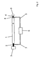
- Fig. 2 describes a device for calibrating force sensors.
- the device consists of a Hopkinson rod 1, which is usually formed as a metallic cylindrical rod with a length of 2 m and a diameter of 20 mm.
- a piezoelectric actuator 2 is non-positively connected to the Hopkinson bar 1.
- a cylindrical metallic counterweight 3 has a diameter of 50 mm and a length of 30 mm. It is glued to the piezoelectric actuator 2, so connected cohesively.
- the sensor 4 to be calibrated, the reference sensor 8 and the coupling mass 9 are mounted.
- the control or regulating electronics 6 controls the piezoelectric actuator 2 via a control line 7.
- the signals of the sensor 4 to be calibrated and the reference sensor 8 are fed to a control electronics 6.
- a control electronics 6 By controlling the piezoelectric actuator 2 with defined electrical signals defined waves are generated in the rod. From the reflection of the waves at the right end of the bar, it is thus possible to generate defined acceleration time or force-time signals.
- the signals can be selectively influenced at the right end of the bar.
- the invention thus makes it possible to influence the signal shape (harmonic signals, pulse-shaped signals), the signal amplitude (typically 20 m / s 2 to 100,000 m / s 2 ) as well as the pulse duration (typically 50 ⁇ s to 500 ⁇ s) of the signals.
- the actual signals of the reference sensor can be used to compare these with the desired signal.
- a predistortion of the drive signals for the actuator can be calculated so that the desired signal is generated at the end of the bar.
- calibration signals can be generated which are matched to the respective sensor to be calibrated.
- the continuum properties of the bar can be used.
- the rod can be excited in the longitudinal eigenfrequency with harmonic signals.
- particularly high signal amplitudes can be achieved at the end of the bar with a minimum of installed electrical power.
- the actuator can be controlled periodically with the same signal. If the period of the control is adapted to the duration of the shaft by the rod, the original wave is superimposed with the newly generated wave. By this superimposition can also be achieved particularly high signal amplitudes at the bar end with a low electrical power input.
Landscapes
- Physics & Mathematics (AREA)
- General Physics & Mathematics (AREA)
- Investigating Strength Of Materials By Application Of Mechanical Stress (AREA)
- Electrical Control Of Air Or Fuel Supplied To Internal-Combustion Engine (AREA)
- Air Bags (AREA)
- Measuring Fluid Pressure (AREA)
Claims (5)
- Procédé de calibrage de capteurs d'accélération et de force au moyen d'une barre d'Hopkinson (1), un dispositif de détection de référence (8) ayant une configuration courante se trouvant sur la barre d'Hopkinson et le capteur (4) à calibrer se trouvant à une extrémité de la barre d'Hopkinson, une excitation au moyen d'un actionneur électromécanique (2) ayant lieu à l'extrémité de la barre d'Hopkinson qui se trouve à l'opposé du capteur pour convertir un signal électrique en une force mécanique, l'actionneur électromécanique pouvant être commandé par le biais d'une électronique de commande (6), caractérisé en ce que l'électronique de commande sert également d'électronique de régulation et la régulation d'une forme d'impulsion d'accélération ou de force est réalisée par- une mesure de la grandeur respective au moyen du dispositif de détection de référence,- un transfert de la grandeur mesurée à l'électronique de commande et de régulation et- une prédistorsion ciblée des signaux de commande de l'actionneur électromécanique.
- Procédé selon la revendication 1, caractérisé en ce que l'amplitude d'accélération ou de force à l'extrémité de la barre d'Hopkinson est maximisée en superposant des ondes.
- Dispositif pour mettre en oeuvre un procédé selon la revendication 1, un dispositif de détection de référence (8) ayant une configuration courante se trouvant sur une barre d'Hopkinson (1) et le capteur (4) à calibrer se trouvant à l'extrémité de la barre d'Hopkinson (1), et un actionneur électromécanique (2) est monté à demeure à une extrémité de la barre d'Hopkinson (1), caractérisé en ce que l'actionneur électromécanique (2) est relié avec une électronique de commande et de régulation (6) par le biais d'une ligne de commande (7),- qu'un contrepoids (3) est fixé à l'actionneur électromécanique (2) à l'opposé de la barre d'Hopkinson (1) et- qu'une ligne de commande (5) mène du dispositif de détection de référence (8) à l'électronique de commande et de régulation (6).
- Dispositif selon la revendication 3, caractérisé en ce que l'actionneur électromécanique (2) est un actionneur piézoélectrique.
- Dispositif selon la revendication 3, caractérisé en ce que l'actionneur électromécanique (2) est un actionneur magnétostrictif.
Applications Claiming Priority (2)
| Application Number | Priority Date | Filing Date | Title |
|---|---|---|---|
| DE102008025866A DE102008025866B4 (de) | 2008-05-29 | 2008-05-29 | Verfahren und Vorrichtung zur Kalibrierung von Beschleunigungs- und Kraftsensoren |
| PCT/DE2009/075023 WO2009143838A1 (fr) | 2008-05-29 | 2009-05-18 | Procédé et dispositif d'étalonnage de capteurs de force et d'accélération |
Publications (3)
| Publication Number | Publication Date |
|---|---|
| EP2158493A1 EP2158493A1 (fr) | 2010-03-03 |
| EP2158493B1 true EP2158493B1 (fr) | 2011-01-12 |
| EP2158493B9 EP2158493B9 (fr) | 2013-05-29 |
Family
ID=41009878
Family Applications (1)
| Application Number | Title | Priority Date | Filing Date |
|---|---|---|---|
| EP09753554.6A Active EP2158493B9 (fr) | 2008-05-29 | 2009-05-18 | Procédé et dispositif d'étalonnage de capteurs de force et d'accélération |
Country Status (11)
| Country | Link |
|---|---|
| US (1) | US9103851B2 (fr) |
| EP (1) | EP2158493B9 (fr) |
| JP (1) | JP5453617B2 (fr) |
| KR (1) | KR101083223B1 (fr) |
| CN (1) | CN101918850B (fr) |
| AT (1) | ATE495449T1 (fr) |
| DE (2) | DE102008025866B4 (fr) |
| ES (1) | ES2359489T3 (fr) |
| RU (1) | RU2438137C1 (fr) |
| TW (1) | TWI410631B (fr) |
| WO (1) | WO2009143838A1 (fr) |
Families Citing this family (26)
| Publication number | Priority date | Publication date | Assignee | Title |
|---|---|---|---|---|
| CN101968496A (zh) * | 2010-06-30 | 2011-02-09 | 中山市嘉科电子有限公司 | 加速度传感器的全自动校正系统 |
| CN102353813B (zh) * | 2011-06-12 | 2012-10-31 | 中北大学 | 宽频带高量程加速度计频率响应特性的校准装置与方法 |
| CN102508187B (zh) * | 2011-11-30 | 2013-10-23 | 中国西电电气股份有限公司 | 一种高压开关机械特性测试仪的速度参数校准装置 |
| CN102735398B (zh) * | 2012-07-16 | 2014-04-16 | 西北核技术研究所 | 基于Hopkinson杆的质量块冲量校准方法 |
| CN103630449B (zh) * | 2013-11-11 | 2016-06-08 | 中国人民解放军空军工程大学 | 一种霍普金森压杆实验子弹速度的控制方法 |
| CN104330316A (zh) * | 2014-10-28 | 2015-02-04 | 中北大学 | 基于脉冲激光产生极窄加速度激励信号的方法 |
| DE102015013401B3 (de) * | 2015-10-19 | 2017-03-02 | Schenck Process Europe Gmbh | Vorrichtung und Verfahren zur Kalibrierung und/oder Justage von Messeinrichtungen für dynamische Kräfte |
| CN105259373B (zh) * | 2015-10-22 | 2019-01-01 | 中国计量科学研究院 | 钢珠发射装置及包含该装置的加速度计动态特性校准系统 |
| CN105372051A (zh) * | 2015-11-27 | 2016-03-02 | 广东电网有限责任公司电力科学研究院 | 一种直线旋转两用断路器机械特性检测装置 |
| US11510649B2 (en) * | 2017-04-25 | 2022-11-29 | Michael D. Bernhardt | Methods and apparatuses for prophylactically treating undetected kidney stones using mechanical waves produced from a tactile transducer |
| CN108037315A (zh) * | 2017-10-30 | 2018-05-15 | 中国科学院上海微系统与信息技术研究所 | 一种高冲击加速度计热灵敏度漂移的测试装置与方法 |
| CN109238561B (zh) * | 2018-09-14 | 2020-05-19 | 上海市计量测试技术研究院 | 一种力传感器动态灵敏度的测量方法 |
| EP3654041B1 (fr) * | 2018-11-16 | 2022-10-19 | Siemens Industry Software NV | Étalonnage d'un détecteur d'accélération de volume |
| CN109282941A (zh) * | 2018-11-22 | 2019-01-29 | 中国电子科技集团公司第四十九研究所 | 一种基于整体式霍普金森杆pvdf传感器的冲击测试系统 |
| WO2020243696A1 (fr) * | 2019-05-30 | 2020-12-03 | Nextinput, Inc. | Systèmes et procédés de test de force en mode continu |
| CN110187145B (zh) * | 2019-06-04 | 2021-06-08 | 西北工业大学 | 利用变截面子弹束产生宽脉冲标定加速度计的装置及方法 |
| CN111678452B (zh) * | 2020-05-18 | 2022-02-18 | 江苏禹治流域管理技术研究院有限公司 | 一种用于分离式霍普金森杆的激光引伸计装置 |
| CN111678453B (zh) * | 2020-05-18 | 2022-02-18 | 江苏禹治流域管理技术研究院有限公司 | 用于分离式霍普金森杆的激光引伸计装置的测试方法 |
| CN112379128B (zh) * | 2020-12-08 | 2022-07-05 | 中北大学 | 基于虚拟惯性力的谐振式微机械加速度计自标定补偿方法 |
| CN114295864B (zh) * | 2021-12-06 | 2024-01-19 | 中国航空工业集团公司北京长城计量测试技术研究所 | 一种产生变脉宽幅值的加速度激励装置及方法 |
| JP2023109353A (ja) * | 2022-01-27 | 2023-08-08 | Imv株式会社 | 加速度ピックアップ校正用治具 |
| CN115575273B (zh) * | 2022-04-08 | 2025-08-19 | 湘潭大学 | 一种霍普金森压杆轴的倾斜标定方法 |
| CN115468866B (zh) * | 2022-09-22 | 2023-07-28 | 宁波大学 | 压电材料的霍普金森一维动态压缩力电特性的试验方法 |
| CN116894210B (zh) * | 2023-09-11 | 2023-12-05 | 深圳市力准传感技术有限公司 | 包含力传感器的电子设备及数据处理方法 |
| CN117665325B (zh) * | 2023-11-17 | 2024-12-17 | 中国航空工业集团公司北京长城计量测试技术研究所 | 一种霍普金森杆冲击加速度传感器校准装置及方法 |
| CN117894576B (zh) * | 2023-12-25 | 2025-04-04 | 西北工业大学 | 一种带有主动线圈保护装置的应力波发生器 |
Family Cites Families (15)
| Publication number | Priority date | Publication date | Assignee | Title |
|---|---|---|---|---|
| US3830091A (en) * | 1973-04-05 | 1974-08-20 | Us Navy | Accelerometer comparator |
| US4292835A (en) * | 1980-02-25 | 1981-10-06 | Raymond Engineering, Inc. | Calibration apparatus and method for strain measuring instruments |
| JPS6335944U (fr) * | 1986-08-26 | 1988-03-08 | ||
| JPS6385461A (ja) | 1986-09-30 | 1988-04-15 | Aisin Seiki Co Ltd | 加速度センサの校正方法と加速度センサ |
| JPH0652270B2 (ja) * | 1989-08-04 | 1994-07-06 | 工業技術院長 | 衝撃加速度計の動的応答特性測定法 |
| DE19845185B4 (de) * | 1998-10-01 | 2005-05-04 | Eads Deutschland Gmbh | Sensor mit Resonanzstruktur sowie Vorrichtung und Verfahren zum Selbsttest eines derartigen Sensors |
| JP2000260105A (ja) | 1999-03-10 | 2000-09-22 | Fujitsu Ltd | 記憶ディスク装置の加速度センサの校正方法 |
| JP4304326B2 (ja) * | 2002-03-29 | 2009-07-29 | 独立行政法人産業技術総合研究所 | 加速度センサの動的線形性計測方法及び装置 |
| US7101599B2 (en) * | 2002-05-06 | 2006-09-05 | Albany International Corp. | Method to increase bond strength and minimize non-uniformities of woven two-layer multiaxial fabrics and fabric produced according to same |
| US7974150B2 (en) * | 2003-05-16 | 2011-07-05 | Schlumberger Technology Corporation | Methods and apparatus of source control for sequential firing of staggered air gun arrays in borehole seismic |
| JP4257416B2 (ja) * | 2003-10-14 | 2009-04-22 | 独立行政法人産業技術総合研究所 | 力センサの動的マトリックス感度計測法とその装置 |
| JP4688534B2 (ja) | 2005-03-23 | 2011-05-25 | クラリオン株式会社 | 加速度の較正方法、及びナビゲーション装置 |
| DE102006031079B4 (de) * | 2006-07-05 | 2010-04-08 | Siemens Ag | Werkzeugmaschine mit einem Piezoaktor |
| CN1955644A (zh) * | 2006-07-07 | 2007-05-02 | 中国航空工业第一集团公司北京长城计量测试技术研究所 | 低频角振动台 |
| JP2008103027A (ja) * | 2006-10-19 | 2008-05-01 | Sony Corp | ディスククリーニング装置、ディスク装置及びディスククリーニング方法 |
-
2008
- 2008-05-29 DE DE102008025866A patent/DE102008025866B4/de not_active Expired - Fee Related
-
2009
- 2009-05-15 TW TW098116094A patent/TWI410631B/zh not_active IP Right Cessation
- 2009-05-18 WO PCT/DE2009/075023 patent/WO2009143838A1/fr not_active Ceased
- 2009-05-18 DE DE502009000286T patent/DE502009000286D1/de active Active
- 2009-05-18 EP EP09753554.6A patent/EP2158493B9/fr active Active
- 2009-05-18 JP JP2010541693A patent/JP5453617B2/ja not_active Expired - Fee Related
- 2009-05-18 US US12/812,511 patent/US9103851B2/en not_active Expired - Fee Related
- 2009-05-18 KR KR1020107013453A patent/KR101083223B1/ko not_active Expired - Fee Related
- 2009-05-18 AT AT09753554T patent/ATE495449T1/de active
- 2009-05-18 RU RU2010123663/28A patent/RU2438137C1/ru active
- 2009-05-18 CN CN2009801016273A patent/CN101918850B/zh not_active Expired - Fee Related
- 2009-05-18 ES ES09753554T patent/ES2359489T3/es active Active
Also Published As
| Publication number | Publication date |
|---|---|
| US20100281944A1 (en) | 2010-11-11 |
| DE102008025866B4 (de) | 2011-04-14 |
| EP2158493A1 (fr) | 2010-03-03 |
| ES2359489T3 (es) | 2011-05-24 |
| CN101918850A (zh) | 2010-12-15 |
| CN101918850B (zh) | 2012-05-30 |
| US9103851B2 (en) | 2015-08-11 |
| EP2158493B9 (fr) | 2013-05-29 |
| TW200951439A (en) | 2009-12-16 |
| JP2011510268A (ja) | 2011-03-31 |
| RU2438137C1 (ru) | 2011-12-27 |
| KR20100092487A (ko) | 2010-08-20 |
| JP5453617B2 (ja) | 2014-03-26 |
| DE502009000286D1 (de) | 2011-02-24 |
| KR101083223B1 (ko) | 2011-11-11 |
| WO2009143838A1 (fr) | 2009-12-03 |
| DE102008025866A1 (de) | 2009-12-31 |
| TWI410631B (zh) | 2013-10-01 |
| ATE495449T1 (de) | 2011-01-15 |
Similar Documents
| Publication | Publication Date | Title |
|---|---|---|
| EP2158493B1 (fr) | Procédé et dispositif d'étalonnage de capteurs de force et d'accélération | |
| DE202008007270U1 (de) | Vorrichtung zur Kalibrierung von Beschleunigungs- und Kraftsensoren | |
| DE2857924C2 (de) | Vorrichtung zur Messung der Dichte von Flüssigkeiten | |
| EP3516358B1 (fr) | Dispositif et procédé d'étalonnage dynamique de capteurs de pression | |
| EP2265920B1 (fr) | Dispositif et procédé de détection de dommages sur une machine de travail | |
| DE102007039548B3 (de) | System und Verfahren zur Schwingungsbeeinflussung | |
| EP3296715B1 (fr) | Procédé d'acquisition de données concernant une pale de rotor pour une éolienne | |
| EP2921842B1 (fr) | Machine de surveillance par résonance | |
| CH683949A5 (de) | Verfahren und Apparat zur Messung der dynamischen Charakteristiken eines Stoss-Accelerometers. | |
| EP2910914B1 (fr) | Dispositif de pesée et procédé de fonctionnement du dispositif de pesée | |
| DE19835578A1 (de) | Vorrichtung zur Ermittlung einer Drehrate | |
| DE10333410B4 (de) | Verfahren und Vorrichtung zur Bestimmung der Eigenfrequenzen eines Lagersystems mit einer gelagerten Welle | |
| DE102014117650A1 (de) | Verfahren zur automatisierten Bestimmung einer dynamischen Steifigkeit eines Objekts | |
| EP0763732B1 (fr) | Dispositif pour l'inspection acoustique d'articles moulés | |
| WO2021083539A1 (fr) | Dispositif d'essai et procédé pour évaluer les caractéristiques de bruit d'un ensemble | |
| EP3056877A1 (fr) | Agencement de mesure de vibration | |
| DE102011116197A1 (de) | Verfahren zur Erkennung eines Dachträgers eines Fahrzeugs | |
| DE102014217363A1 (de) | Verfahren und vorrichtung an rotorsystemen | |
| DE10141518B4 (de) | Vorrichtung zur Erzeugung mechanischer Schwingungen in einem festen Material | |
| DE102010003400B4 (de) | Verfahren und Vorrichtung zum Abmindern von Schwingungen einer Struktur | |
| DE10318069A1 (de) | Drucksensor nach dem Resonatorprinzip und Verfahren zu dessen Betrieb | |
| DE2556073A1 (de) | Verfahren zum pruefen von schwingungsdaempfern eines fahrzeuges im eingebauten zustand und vorrichtung zur durchfuehrung dieses verfahrens | |
| Volkers et al. | A method for high-shock accelerometer calibration comparison using a 2-DOF model | |
| DE102008003086A1 (de) | Vorrichtung zur Durchführung von Pyroschocktests mit Hilfe von piezoelektrischen Aktoren | |
| DE102009052132A1 (de) | Medizinische Vorrichtung zum Behandeln von biologischem Gewebe |
Legal Events
| Date | Code | Title | Description |
|---|---|---|---|
| PUAI | Public reference made under article 153(3) epc to a published international application that has entered the european phase |
Free format text: ORIGINAL CODE: 0009012 |
|
| 17P | Request for examination filed |
Effective date: 20091224 |
|
| AK | Designated contracting states |
Kind code of ref document: A1 Designated state(s): AT BE BG CH CY CZ DE DK EE ES FI FR GB GR HR HU IE IS IT LI LT LU LV MC MK MT NL NO PL PT RO SE SI SK TR |
|
| AX | Request for extension of the european patent |
Extension state: AL BA RS |
|
| GRAP | Despatch of communication of intention to grant a patent |
Free format text: ORIGINAL CODE: EPIDOSNIGR1 |
|
| GRAS | Grant fee paid |
Free format text: ORIGINAL CODE: EPIDOSNIGR3 |
|
| GRAA | (expected) grant |
Free format text: ORIGINAL CODE: 0009210 |
|
| AK | Designated contracting states |
Kind code of ref document: B1 Designated state(s): AT BE BG CH CY CZ DE DK EE ES FI FR GB GR HR HU IE IS IT LI LT LU LV MC MK MT NL NO PL PT RO SE SI SK TR |
|
| AX | Request for extension of the european patent |
Extension state: RS |
|
| REG | Reference to a national code |
Ref country code: GB Ref legal event code: FG4D Free format text: NOT ENGLISH |
|
| REG | Reference to a national code |
Ref country code: CH Ref legal event code: EP |
|
| REG | Reference to a national code |
Ref country code: IE Ref legal event code: FG4D Free format text: LANGUAGE OF EP DOCUMENT: GERMAN |
|
| REF | Corresponds to: |
Ref document number: 502009000286 Country of ref document: DE Date of ref document: 20110224 Kind code of ref document: P |
|
| REG | Reference to a national code |
Ref country code: DE Ref legal event code: R096 Ref document number: 502009000286 Country of ref document: DE Effective date: 20110224 |
|
| REG | Reference to a national code |
Ref country code: ES Ref legal event code: FG2A Ref document number: 2359489 Country of ref document: ES Kind code of ref document: T3 Effective date: 20110524 |
|
| REG | Reference to a national code |
Ref country code: NL Ref legal event code: VDEP Effective date: 20110112 |
|
| LTIE | Lt: invalidation of european patent or patent extension |
Effective date: 20110112 |
|
| PG25 | Lapsed in a contracting state [announced via postgrant information from national office to epo] |
Ref country code: HR Free format text: LAPSE BECAUSE OF FAILURE TO SUBMIT A TRANSLATION OF THE DESCRIPTION OR TO PAY THE FEE WITHIN THE PRESCRIBED TIME-LIMIT Effective date: 20110112 Ref country code: IS Free format text: LAPSE BECAUSE OF FAILURE TO SUBMIT A TRANSLATION OF THE DESCRIPTION OR TO PAY THE FEE WITHIN THE PRESCRIBED TIME-LIMIT Effective date: 20110512 Ref country code: GR Free format text: LAPSE BECAUSE OF FAILURE TO SUBMIT A TRANSLATION OF THE DESCRIPTION OR TO PAY THE FEE WITHIN THE PRESCRIBED TIME-LIMIT Effective date: 20110413 Ref country code: PT Free format text: LAPSE BECAUSE OF FAILURE TO SUBMIT A TRANSLATION OF THE DESCRIPTION OR TO PAY THE FEE WITHIN THE PRESCRIBED TIME-LIMIT Effective date: 20110512 Ref country code: NO Free format text: LAPSE BECAUSE OF FAILURE TO SUBMIT A TRANSLATION OF THE DESCRIPTION OR TO PAY THE FEE WITHIN THE PRESCRIBED TIME-LIMIT Effective date: 20110412 Ref country code: LV Free format text: LAPSE BECAUSE OF FAILURE TO SUBMIT A TRANSLATION OF THE DESCRIPTION OR TO PAY THE FEE WITHIN THE PRESCRIBED TIME-LIMIT Effective date: 20110112 Ref country code: SE Free format text: LAPSE BECAUSE OF FAILURE TO SUBMIT A TRANSLATION OF THE DESCRIPTION OR TO PAY THE FEE WITHIN THE PRESCRIBED TIME-LIMIT Effective date: 20110112 Ref country code: LT Free format text: LAPSE BECAUSE OF FAILURE TO SUBMIT A TRANSLATION OF THE DESCRIPTION OR TO PAY THE FEE WITHIN THE PRESCRIBED TIME-LIMIT Effective date: 20110112 |
|
| REG | Reference to a national code |
Ref country code: IE Ref legal event code: FD4D |
|
| PG25 | Lapsed in a contracting state [announced via postgrant information from national office to epo] |
Ref country code: FI Free format text: LAPSE BECAUSE OF FAILURE TO SUBMIT A TRANSLATION OF THE DESCRIPTION OR TO PAY THE FEE WITHIN THE PRESCRIBED TIME-LIMIT Effective date: 20110112 Ref country code: NL Free format text: LAPSE BECAUSE OF FAILURE TO SUBMIT A TRANSLATION OF THE DESCRIPTION OR TO PAY THE FEE WITHIN THE PRESCRIBED TIME-LIMIT Effective date: 20110112 Ref country code: CY Free format text: LAPSE BECAUSE OF FAILURE TO SUBMIT A TRANSLATION OF THE DESCRIPTION OR TO PAY THE FEE WITHIN THE PRESCRIBED TIME-LIMIT Effective date: 20110112 Ref country code: BG Free format text: LAPSE BECAUSE OF FAILURE TO SUBMIT A TRANSLATION OF THE DESCRIPTION OR TO PAY THE FEE WITHIN THE PRESCRIBED TIME-LIMIT Effective date: 20110412 Ref country code: SI Free format text: LAPSE BECAUSE OF FAILURE TO SUBMIT A TRANSLATION OF THE DESCRIPTION OR TO PAY THE FEE WITHIN THE PRESCRIBED TIME-LIMIT Effective date: 20110112 Ref country code: PL Free format text: LAPSE BECAUSE OF FAILURE TO SUBMIT A TRANSLATION OF THE DESCRIPTION OR TO PAY THE FEE WITHIN THE PRESCRIBED TIME-LIMIT Effective date: 20110112 |
|
| PG25 | Lapsed in a contracting state [announced via postgrant information from national office to epo] |
Ref country code: IE Free format text: LAPSE BECAUSE OF FAILURE TO SUBMIT A TRANSLATION OF THE DESCRIPTION OR TO PAY THE FEE WITHIN THE PRESCRIBED TIME-LIMIT Effective date: 20110112 Ref country code: DK Free format text: LAPSE BECAUSE OF FAILURE TO SUBMIT A TRANSLATION OF THE DESCRIPTION OR TO PAY THE FEE WITHIN THE PRESCRIBED TIME-LIMIT Effective date: 20110112 Ref country code: EE Free format text: LAPSE BECAUSE OF FAILURE TO SUBMIT A TRANSLATION OF THE DESCRIPTION OR TO PAY THE FEE WITHIN THE PRESCRIBED TIME-LIMIT Effective date: 20110112 |
|
| PLBE | No opposition filed within time limit |
Free format text: ORIGINAL CODE: 0009261 |
|
| STAA | Information on the status of an ep patent application or granted ep patent |
Free format text: STATUS: NO OPPOSITION FILED WITHIN TIME LIMIT |
|
| BERE | Be: lapsed |
Owner name: SPEKTRA SCHWINGUNGSTECHNIK UND AKUSTIK G.M.B.H. D Effective date: 20110531 |
|
| PG25 | Lapsed in a contracting state [announced via postgrant information from national office to epo] |
Ref country code: RO Free format text: LAPSE BECAUSE OF FAILURE TO SUBMIT A TRANSLATION OF THE DESCRIPTION OR TO PAY THE FEE WITHIN THE PRESCRIBED TIME-LIMIT Effective date: 20110112 Ref country code: CZ Free format text: LAPSE BECAUSE OF FAILURE TO SUBMIT A TRANSLATION OF THE DESCRIPTION OR TO PAY THE FEE WITHIN THE PRESCRIBED TIME-LIMIT Effective date: 20110112 Ref country code: SK Free format text: LAPSE BECAUSE OF FAILURE TO SUBMIT A TRANSLATION OF THE DESCRIPTION OR TO PAY THE FEE WITHIN THE PRESCRIBED TIME-LIMIT Effective date: 20110112 |
|
| 26N | No opposition filed |
Effective date: 20111013 |
|
| PG25 | Lapsed in a contracting state [announced via postgrant information from national office to epo] |
Ref country code: MT Free format text: LAPSE BECAUSE OF FAILURE TO SUBMIT A TRANSLATION OF THE DESCRIPTION OR TO PAY THE FEE WITHIN THE PRESCRIBED TIME-LIMIT Effective date: 20110112 Ref country code: MC Free format text: LAPSE BECAUSE OF NON-PAYMENT OF DUE FEES Effective date: 20110531 |
|
| REG | Reference to a national code |
Ref country code: DE Ref legal event code: R097 Ref document number: 502009000286 Country of ref document: DE Effective date: 20111013 |
|
| PG25 | Lapsed in a contracting state [announced via postgrant information from national office to epo] |
Ref country code: BE Free format text: LAPSE BECAUSE OF NON-PAYMENT OF DUE FEES Effective date: 20110531 |
|
| PG25 | Lapsed in a contracting state [announced via postgrant information from national office to epo] |
Ref country code: MK Free format text: LAPSE BECAUSE OF FAILURE TO SUBMIT A TRANSLATION OF THE DESCRIPTION OR TO PAY THE FEE WITHIN THE PRESCRIBED TIME-LIMIT Effective date: 20110112 |
|
| PG25 | Lapsed in a contracting state [announced via postgrant information from national office to epo] |
Ref country code: LU Free format text: LAPSE BECAUSE OF NON-PAYMENT OF DUE FEES Effective date: 20110518 |
|
| PG25 | Lapsed in a contracting state [announced via postgrant information from national office to epo] |
Ref country code: TR Free format text: LAPSE BECAUSE OF FAILURE TO SUBMIT A TRANSLATION OF THE DESCRIPTION OR TO PAY THE FEE WITHIN THE PRESCRIBED TIME-LIMIT Effective date: 20110112 |
|
| PG25 | Lapsed in a contracting state [announced via postgrant information from national office to epo] |
Ref country code: HU Free format text: LAPSE BECAUSE OF FAILURE TO SUBMIT A TRANSLATION OF THE DESCRIPTION OR TO PAY THE FEE WITHIN THE PRESCRIBED TIME-LIMIT Effective date: 20110112 |
|
| REG | Reference to a national code |
Ref country code: CH Ref legal event code: PL |
|
| PG25 | Lapsed in a contracting state [announced via postgrant information from national office to epo] |
Ref country code: CH Free format text: LAPSE BECAUSE OF NON-PAYMENT OF DUE FEES Effective date: 20130531 Ref country code: LI Free format text: LAPSE BECAUSE OF NON-PAYMENT OF DUE FEES Effective date: 20130531 |
|
| REG | Reference to a national code |
Ref country code: AT Ref legal event code: MM01 Ref document number: 495449 Country of ref document: AT Kind code of ref document: T Effective date: 20140518 |
|
| PG25 | Lapsed in a contracting state [announced via postgrant information from national office to epo] |
Ref country code: AT Free format text: LAPSE BECAUSE OF NON-PAYMENT OF DUE FEES Effective date: 20140518 |
|
| REG | Reference to a national code |
Ref country code: DE Ref legal event code: R082 Ref document number: 502009000286 Country of ref document: DE Representative=s name: LIPPERT STACHOW PATENTANWAELTE RECHTSANWAELTE , DE Ref country code: DE Ref legal event code: R082 Ref document number: 502009000286 Country of ref document: DE Representative=s name: PATENTANWAELTE LIPPERT, STACHOW & PARTNER, DE |
|
| REG | Reference to a national code |
Ref country code: FR Ref legal event code: PLFP Year of fee payment: 8 |
|
| REG | Reference to a national code |
Ref country code: FR Ref legal event code: PLFP Year of fee payment: 9 |
|
| REG | Reference to a national code |
Ref country code: FR Ref legal event code: PLFP Year of fee payment: 10 |
|
| PGFP | Annual fee paid to national office [announced via postgrant information from national office to epo] |
Ref country code: FR Payment date: 20200519 Year of fee payment: 12 Ref country code: DE Payment date: 20200528 Year of fee payment: 12 Ref country code: ES Payment date: 20200618 Year of fee payment: 12 |
|
| PGFP | Annual fee paid to national office [announced via postgrant information from national office to epo] |
Ref country code: GB Payment date: 20200522 Year of fee payment: 12 Ref country code: IT Payment date: 20200528 Year of fee payment: 12 |
|
| REG | Reference to a national code |
Ref country code: DE Ref legal event code: R119 Ref document number: 502009000286 Country of ref document: DE |
|
| GBPC | Gb: european patent ceased through non-payment of renewal fee |
Effective date: 20210518 |
|
| PG25 | Lapsed in a contracting state [announced via postgrant information from national office to epo] |
Ref country code: GB Free format text: LAPSE BECAUSE OF NON-PAYMENT OF DUE FEES Effective date: 20210518 Ref country code: DE Free format text: LAPSE BECAUSE OF NON-PAYMENT OF DUE FEES Effective date: 20211201 |
|
| PG25 | Lapsed in a contracting state [announced via postgrant information from national office to epo] |
Ref country code: FR Free format text: LAPSE BECAUSE OF NON-PAYMENT OF DUE FEES Effective date: 20210531 |
|
| REG | Reference to a national code |
Ref country code: ES Ref legal event code: FD2A Effective date: 20220804 |
|
| PG25 | Lapsed in a contracting state [announced via postgrant information from national office to epo] |
Ref country code: ES Free format text: LAPSE BECAUSE OF NON-PAYMENT OF DUE FEES Effective date: 20210519 |
|
| PG25 | Lapsed in a contracting state [announced via postgrant information from national office to epo] |
Ref country code: IT Free format text: LAPSE BECAUSE OF NON-PAYMENT OF DUE FEES Effective date: 20200518 |
|
| PG25 | Lapsed in a contracting state [announced via postgrant information from national office to epo] |
Ref country code: IT Free format text: LAPSE BECAUSE OF NON-PAYMENT OF DUE FEES Effective date: 20210518 |