EP2158654B1 - Rohranordnung für eine offshore-anlage - Google Patents
Rohranordnung für eine offshore-anlage Download PDFInfo
- Publication number
- EP2158654B1 EP2158654B1 EP07765359A EP07765359A EP2158654B1 EP 2158654 B1 EP2158654 B1 EP 2158654B1 EP 07765359 A EP07765359 A EP 07765359A EP 07765359 A EP07765359 A EP 07765359A EP 2158654 B1 EP2158654 B1 EP 2158654B1
- Authority
- EP
- European Patent Office
- Prior art keywords
- cable
- tubing arrangement
- tube
- tube section
- seabed
- Prior art date
- Legal status (The legal status is an assumption and is not a legal conclusion. Google has not performed a legal analysis and makes no representation as to the accuracy of the status listed.)
- Active
Links
Images



Classifications
-
- H—ELECTRICITY
- H02—GENERATION; CONVERSION OR DISTRIBUTION OF ELECTRIC POWER
- H02G—INSTALLATION OF ELECTRIC CABLES OR LINES, OR OF COMBINED OPTICAL AND ELECTRIC CABLES OR LINES
- H02G9/00—Installations of electric cables or lines in or on the ground or water
-
- H—ELECTRICITY
- H02—GENERATION; CONVERSION OR DISTRIBUTION OF ELECTRIC POWER
- H02G—INSTALLATION OF ELECTRIC CABLES OR LINES, OR OF COMBINED OPTICAL AND ELECTRIC CABLES OR LINES
- H02G1/00—Methods or apparatus specially adapted for installing, maintaining, repairing or dismantling electric cables or lines
- H02G1/06—Methods or apparatus specially adapted for installing, maintaining, repairing or dismantling electric cables or lines for laying cables, e.g. laying apparatus on vehicle
- H02G1/10—Methods or apparatus specially adapted for installing, maintaining, repairing or dismantling electric cables or lines for laying cables, e.g. laying apparatus on vehicle in or under water
-
- H—ELECTRICITY
- H02—GENERATION; CONVERSION OR DISTRIBUTION OF ELECTRIC POWER
- H02G—INSTALLATION OF ELECTRIC CABLES OR LINES, OR OF COMBINED OPTICAL AND ELECTRIC CABLES OR LINES
- H02G9/00—Installations of electric cables or lines in or on the ground or water
- H02G9/06—Installations of electric cables or lines in or on the ground or water in underground tubes or conduits; Tubes or conduits therefor
-
- E—FIXED CONSTRUCTIONS
- E02—HYDRAULIC ENGINEERING; FOUNDATIONS; SOIL SHIFTING
- E02B—HYDRAULIC ENGINEERING
- E02B17/00—Artificial islands mounted on piles or like supports, e.g. platforms on raisable legs or offshore constructions; Construction methods therefor
- E02B2017/0091—Offshore structures for wind turbines
-
- E—FIXED CONSTRUCTIONS
- E02—HYDRAULIC ENGINEERING; FOUNDATIONS; SOIL SHIFTING
- E02B—HYDRAULIC ENGINEERING
- E02B17/00—Artificial islands mounted on piles or like supports, e.g. platforms on raisable legs or offshore constructions; Construction methods therefor
- E02B2017/0095—Connections of subsea risers, piping or wiring with the offshore structure
Definitions
- the present invention relates to a tubing arrangement for an offshore facility, such as an offshore wind turbine or an oil rig.
- the tubing arrangement of the present invention is preferably suitable for holding one or more cables. More particularly, the present invention relates to a tubing arrangement which is capable of providing improved protection for cables, tubes, etc. arranged in the tubing arrangement. Furthermore, the present invention relates to an offshore facility comprising such a tubing arrangement, and to a method of mounting a cable on an offshore facility.
- J-tubes are tubes having the shape of a J, i.e. having a curved part arranged near an end of the tube.
- the J-tube may be mounted on the offshore facility in such a manner that it substantially follows a tower construction of the offshore facility, and in such a manner that the curved part is arranged at or near the seabed.
- the cables arranged in the J-tube will emerge from the J-tube in a direction which substantially follows the seabed, and it is therefore easy to flush the cables into the seabed in order to protect them from wear and from damage caused by passing vessels, such as trawlers etc.
- EP 1 616 377 discloses a protective device for cables and conduits.
- the protective device may be mounted at the end of a J-tube, and it comprises a plurality of pipe elements, each formed by joining together two pipe halves.
- the pipe segments are joined to one another to form a pipe for accommodating a cable or a conduit in such a manner that they are capable of pivoting relatively to each other.
- This allows the cable or conduit accommodated in the pipe to bend, the maximum bending radius being defined and limited by the allowed pivoting movement between two neighbouring pipe segments.
- the J-tube disclosed in EP 1 616 377 may comprise a telescopic function allowing the length of the J-tube to be adjusted in order to ensure that the curved part of the J-tube is arranged at the seabed.
- the telescopic arrangement disclosed in EP 1 616 377 is relatively mechanically complex, and it is therefore relatively expensive to manufacture. Furthermore, there is a risk that the telescopic function jams, e.g. due to corrosions or due to sediments or sand entering part of the tube.
- an object of the invention to provide a tubing arrangement for an offshore facility, the tubing arrangement being simple to manufacture and operate.
- the offshore facility is preferably an offshore wind turbine, but it could alternatively be an oil rig or another suitable kind of offshore facility. This will be described further below.
- 'tubing arrangement' should be interpreted to mean an arrangement comprising one or more tubes or tube sections.
- the tube arrangement is preferably adapted to hold cables, wiring and/or tubes, etc. which should be connected to the offshore facility.
- the tubing arrangement according to the invention comprises two tube sections interconnected by means of a joint part.
- the first tube section comprises a curved part, and, is or forms part of a J-tube as described above.
- the second tube section is substantially rigid, i.e. it is capable of maintaining its shape, and it is thereby capable of protecting cables or other items arranged inside the tubing arrangement.
- the first tube section is preferably mounted on the offshore facility in such a manner that the first tube section extends along a longitudinal direction defined by the offshore facility, and in such a manner that the curved part is arranged at a position at or near the seabed.
- the tubing arrangement holds a cable
- the cable will run from a part of the offshore facility which is above the water surface, through the first tube section and the second tube section, via the joint part.
- the first tube section is ideally positioned, i.e.
- the curved part is arranged immediately adjacent to the seabed, then substantially the entire length of the second tube section may be arranged along the seabed, provided that the second tube section is substantially straight, and the cable emerging from the second tube section at the end arranged opposite to the joint part can readily be flushed into the seabed in order to provide protection.
- the curved part of the first tube section is arranged at a distance from the seabed, e.g. due to the occurrence of a scour hole
- the second tube section is allowed to pivot relatively to the first tube section, by means of the joint part. Accordingly, gravity will pull the second tube section downwards until part of it abuts the seabed, possibly a part of the seabed being inside the scour hole.
- the part of the cable which would otherwise hang freely between the end of the first tube section and the seabed will be protected by the rigid second tube section.
- the cable is protected without the requirement for complex mechanical arrangements.
- the first tube section when using a tubing arrangement according to the first aspect of the invention, it is no longer required that the curved part of the first tube section is arranged immediately adjacent to the seabed. Accordingly, there is no need to know the exact distance to the seabed, and it is not necessary to adjust the position of the curved part of the first tube section.
- the tubing arrangement further comprises a flexible tube connected to the second tube section at an end arranged opposite to the end which is connected to the joint part.
- a flexible tube connected to the second tube section at an end arranged opposite to the end which is connected to the joint part.
- the joint part may comprise a two-dimensional hinge, i.e. a hinge which is only capable of pivoting about a single pivot axis.
- the relative pivoting movements between the first tube section and the second tube section is limited to movements about said pivoting axis.
- the pivoting axis is preferably arranged substantially horizontally in order to allow a movement of the second tube section caused by gravity as described above.
- the joint part may comprise a spherical joint.
- the first tube section and the second tube section are allowed to move relatively to each other in a more freely manner, e.g. vertically as well as horizontally.
- the exact position of the sea vessel relatively to the direction of the curved part of the first tube section is not critical. Accordingly, the sea vessel can be positioned while taking other aspects into consideration, e.g. wind direction, wind speed, current direction, etc.
- the joint part may comprise flexible tubing.
- the first tube section and the second tube sections are also allowed to move relatively freely relatively to each other.
- the joint part may be or comprise any other suitably joint or hinge, as long as the first tube part and the second tube part are allowed to pivot relatively to each other.
- the tubing arrangement may further comprise at least one cable arranged in interior parts of the tube sections.
- At least one of the cable(s) may be a power cable, e.g. for supplying power to the offshore facility or for delivering power generated in an offshore wind turbine to a power grid on shore.
- the tubing arrangement may comprise one or more wires and/or one or more tubes, e.g. for conveying oil from an oil rig to a plant on shore, or for conveying fluids, such as hydraulic fluids, to the offshore facility.
- the second tube section may be essentially non-curved in a plane defined by the curvature of the first tube section. According to this embodiment, the second tube section defines a substantially straight line in the plane defined by the curvature of the first tube section. However, the second tube section may be curved in other planes, such as a plane being substantially perpendicular to the plane defined by the curvature of the first tube section.
- an offshore facility comprising a tower construction mounted at the seabed and a tubing arrangement according to the first aspect of the invention, at least part of said tubing arrangement being mounted on the tower construction.
- the offshore facility may advantageously be a wind turbine.
- the offshore facility - may be any other suitable kind of offshore facility, such as an oil rig.
- a cable is mounted on an offshore facility using a tubing arrangement essentially according to the first aspect of the invention. At least part of the tubing arrangement, preferably at least part of the first tube section, is mounted on the offshore facility, e.g. as described previously.
- the cable is inserted in the tubing arrangement via the flexible tube, and the flexibility of the flexible tube allows an entrance opening of that tube to be manipulated to a desired position. Accordingly, the entrance opening may be arranged at a level which is above a level defined by the seabed, and accordingly the step of inserting the cable is performed above the level, defined by the seabed. If a cable is inserted in a tubing arrangement at a level which is at or near the seabed, there is a risk that sand and/or sediment is introduced in the tubing arrangement along with the cable. This is very undesirable since it inhibits sliding movements of the cable in the tubing arrangement, and since it may cause damage to the cable and/or to the tubing arrangement. It is therefore an advantage that the step of inserting the cable is performed above a level defined by the seabed.
- the step of inserting the cable is performed above a level defined by the water surface.
- sediment or impurities contained in the water substantially above the seabed is introduced in the tubing arrangement along with the cable.
- salt water is introduced in the tubing arrangement during insertion of the cable.
- the cable can be inserted in the tubing arrangement completely without the use of divers.
- the method may further comprise the step of positioning the flexible tube on or in the vicinity of a floating facility, and the step of inserting the cable may be performed from the floating facility.
- the cable, as well as the personnel installing the cable, is preferably positioned on the floating facility.
- the floating facility may be a sea vessel, such as a boat or a barge adapted to carry the cable from a position on shore to the site of the offshore facility.
- the step of inserting the cable may comprise the steps of:
- the method may further comprise the step of flushing the flexible tube into the seabed.
- the flexible tube is preferably lowered to a position along the seabed when the step of inserting the cable has been completed. When the flexible tube has been lowered to this position, it is flushed into the seabed along with the cable.
- the method may further comprise the steps of:
- Fig. 1 is a schematic drawing of a tubing arrangement 1 according to an embodiment of the invention.
- the tubing arrangement 1 comprises a first tube section 2 in the form of a J-tube, i.e. with a curved part 3, a second tube section 4 being substantially rigid, and a flexible tube 5.
- the first tube section 2 and the second tube section 4 are connected via a joint part 6, and the first tube section 2 and the second tube section 4 are thereby allowed to pivot relatively to each other. This will be explained further below.
- the first tube section 2 is mounted on a tower construction 7 for an offshore facility, such as an offshore wind turbine.
- the first tube section 2 is mounted in such a manner that it extends above the level of a water surface 8, and in such a manner that the curved part 3 is arranged near the seabed 9.
- Fig. 1 the flexible tube 5 is coiled up. Thereby it is indicated that a cable has not yet been inserted into the tubing arrangement 1.
- Fig. 2 shows the tubing arrangement 1 of Fig. 1 .
- the flexible tube 5 has been uncoiled, and the end of the flexible tube 5 is positioned on a floating vessel 10, e.g. a boat or a barge.
- a floating vessel e.g. a boat or a barge.
- the joint part 6 has been pivoted relatively to the situation shown in Fig. 1 , and the second tube section 4 has thereby been lowered slightly towards the seabed 9.
- a cable (not shown) can be inserted in the tubing arrangement 1 from the vessel 10 via the flexible tube 5. As described above, this may advantageously be done by introducing a messenger wire into the tubing arrangement 1 and subsequently pulling the cable into the tubing arrangement 1 via the messenger wire.
- the end of the flexible tube 5 is positioned on the vessel 10, because it is relatively easy to insert the cable from the vessel 10 in the manner described above, rather than having to introduce the cable into the tubing arrangement 1 from a position at the seabed by means of divers and/or remotely operable vehicles (ROVs). This also considerably reduces the installation costs. Furthermore, the fact that the introduction of the cable takes place above the water surface 8 prevents sand, sediment, salt water, etc. from entering the tubing arrangement 1 along with the cable. This has already been described above.
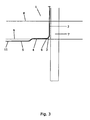
- Fig. 3 shows the tubing arrangement 1 of Figs. 1 and 2 .
- the cable 11 has been introduced into the tubing arrangement 1, and the vessel has been removed from the site.
- the joint part 6 has been pivoted further, and the second tube section 4 is now lying along the seabed 9.
- the flexible tube 5 as well as the cable 11 has been flushed into the seabed 9 in order to protect the cable 11 as previously described.
- Fig. 4 shows a tubing arrangement 1 similar to the one shown in Figs. 1-3 , and similar parts have therefore been provided with identical reference numerals. Accordingly, a detailed description of the various parts will not be presented here.
- the tubing arrangement 1 of Fig. 4 is shown in a situation where the flexible tube 5 has been flushed into the seabed 9, i.e. a situation corresponding to the one illustrated in Fig. 3 .
- Fig. 4 the first tube section 2 is attached to the tower construction 7 of the offshore facility by means of a carrier structure 12.
- the cable 11 and the tubing arrangement 1 have been installed in a manner substantially as described above with reference to Figs. 1-3 .
- a scour hole 13 has formed in a region near the tower construction 7. Accordingly, there is a gap between the curved part 3 of the first tube section 2 and the seabed 9.
- the joint part 6 is pivoted to lower the second tube section 4 as described above with reference to Figs. 2 and 3 , the pivoting movement is continued until the end 14 of the second tube section 4 which is connected to the flexible tube 5 abuts the seabed 9.
- the scour hole 13 has the effect that the end 14 is the only part of the second tube section 4 which abuts the seabed 9.
- the second tube section 4 protects the part of the cable 11 arranged inside the second tube section 4, which would otherwise be hanging freely and exposed. Furthermore, it is ensured that the cable 11, along with the flexible tube 5, is flushed into the seabed 9 from the point where the cable 11 emerges from the second tube section 4.
- the joint part 6 ensures that the end 14 abuts the seabed 9, even if the scour, hole 13 is very deep or extends to a position far from the tower construction 7. This is very advantageous, since a high degree of protection for the cable 11 is provided without the requirement of complicated mechanical constructions.
Landscapes
- Laying Of Electric Cables Or Lines Outside (AREA)
- Supports For Pipes And Cables (AREA)
Claims (14)
- Rohrvorrichtung (1) zur Aufnahme eines oder mehrerer an einer Offshore-Einrichtung montierten Kabel, wobei die Rohrvorrichtung (1) umfasst:- einen ersten Rohrabschnitt (2) mit einem gekrümmten Teil (3), wobei der erste Rohrabschnitt (2) ein J-Rohr bildet oder ein Teil davon ist,- einen zweiten Rohrabschnitt (4), wobei der zweite Rohrabschnitt (4) im Wesentlichen steif ist,- ein Verbindungsteil (6), das den zweiten Rohrabschnitt (4) und den gekrümmten Teil (3) des ersten Rohrabschnitts (2) verbindet, wodurch die beiden Rohrabschnitte (2, 4) gegeneinander drehbar sind, und- einen Schlauch (5), der mit dem Ende des zweiten Rohrabschnitts (4) gegenüber dem Ende verbunden ist, das mit dem Verbindungsteil (6) verbunden ist.
- Rohrvorrichtung (1) nach Anspruch 1 , wobei das Verbindungsteil (6) ein zweidimensionales Scharnier umfasst.
- Rohrvorrichtung (1) nach Anspruch 1 , wobei das Verbindungsteil (6) ein Kugelgelenk umfasst.
- Rohrvorrichtung (1) nach Anspruch 1, wobei das Verbindungsteil (6) Schlauch umfasst.
- Rohrvorrichtung (1) nach einem der vorhergehenden Ansprüche, weiterhin umfassend mindestens ein Kabel (11), das im Inneren der Rohrabschnitte (2, 4) angeordnet ist.
- Rohrvorrichtung (1) nach einem der vorhergehenden Ansprüche, wobei der zweite Rohrabschnitt (4) in einer durch die Krümmung des ersten Rohrabschnitts (2) festgelegten Ebene im Wesentlichen nicht gekrümmt ist.
- Offshore-Einrichtung, umfassend ein Turmbauwerk (7), das auf dem Meeresboden (9) aufgestellt ist, und eine Rohrvorrichtung (1) nach einem der vorhergehenden Ansprüche, wobei mindestens ein Teil der Rohrvorrichtung (1) am Turmbauwerk (7) montiert ist.
- Offshore-Einrichtung nach Anspruch 7, wobei die Offshore-Einrichtung einer Windkraftanlage ist.
- Verfahren zum Anbringen eines Kabels (11) an einer Offshore-Einrichtung, wobei das Verfahren folgende Schritte umfasst:- Bereitstellen einer Rohrvorrichtung (1) nach Anspruch 1 und- Einführen des Kabels (11) in die Rohrvorrichtung (1) mithilfe des Schlauchs (5),wobei der Schritt des Einführens des Kabels (11) oberhalb einer durch den Meeresboden (9) festgelegten Höhe stattfindet.
- Verfahren nach Anspruch 9, wobei der Schritt des Einführens des Kabels (11) oberhalb einer durch die Wasseroberfläche (8) festgelegten Höhe stattfindet.
- Verfahren nach Anspruch 9 oder 10, weiterhin umfassend den Schritt des Positionierens des Schlauchs (5) auf oder in der Nähe einer Schwimmvorrichtung und wobei der Schritt des Einführens des Kabels (11) von der Schwimmvorrichtung aus durchgeführt wird.
- Verfahren nach einem der Ansprüche 9-11, wobei der Schritt des Einführens des Kabels (11) folgende Schritte umfasst:- Einführen eines Tragkabels in die Rohrvorrichtung (1) und- Ziehen des Kabels (11) in die Rohrvorrichtung (1) mithilfe des Tragkabels.
- Verfahren nach einem der Ansprüche 9-12, weiterhin umfassend den Schritt des Spülens des Schlauchs (5) in den Meeresboden (9).
- Verfahren nach einem der Ansprüche 9-13, weiterhin umfassend die folgenden Schritte:- Montieren des ersten Rohrabschnitts (2) an der Offshore-Einrichtung und- Drehen des Verbindungsteils (6), bis mindestens einen Teil des zweiten Rohrabschnitt (4) den Meeresboden (9) berührt.
Applications Claiming Priority (1)
| Application Number | Priority Date | Filing Date | Title |
|---|---|---|---|
| PCT/EP2007/055716 WO2008151660A1 (en) | 2007-06-11 | 2007-06-11 | A tubing arrangement for an offshore facility |
Publications (2)
| Publication Number | Publication Date |
|---|---|
| EP2158654A1 EP2158654A1 (de) | 2010-03-03 |
| EP2158654B1 true EP2158654B1 (de) | 2011-08-10 |
Family
ID=39048897
Family Applications (1)
| Application Number | Title | Priority Date | Filing Date |
|---|---|---|---|
| EP07765359A Active EP2158654B1 (de) | 2007-06-11 | 2007-06-11 | Rohranordnung für eine offshore-anlage |
Country Status (6)
| Country | Link |
|---|---|
| US (1) | US20100196100A1 (de) |
| EP (1) | EP2158654B1 (de) |
| KR (1) | KR20100020469A (de) |
| CN (1) | CN101715622A (de) |
| AT (1) | ATE520181T1 (de) |
| WO (1) | WO2008151660A1 (de) |
Cited By (2)
| Publication number | Priority date | Publication date | Assignee | Title |
|---|---|---|---|---|
| WO2013113407A2 (en) | 2012-02-02 | 2013-08-08 | Siemens Aktiengesellschaft | Cable assembly holding apparatus |
| CN103574162A (zh) * | 2012-08-06 | 2014-02-12 | 西门子公司 | 缆线悬挂装置 |
Families Citing this family (19)
| Publication number | Priority date | Publication date | Assignee | Title |
|---|---|---|---|---|
| EP2110910A1 (de) * | 2008-04-17 | 2009-10-21 | OpenHydro Group Limited | Verbessertes Turbineninstallationsverfahren |
| GB2463940C (en) * | 2008-10-03 | 2012-07-18 | Tekmar Energy Ltd | Protection assembly for elongate flexible member and method of installation of such member |
| GB0900500D0 (en) * | 2009-01-14 | 2009-02-11 | Rolls Royce Plc | Submersible cable arrangement |
| GB0903068D0 (en) | 2009-02-24 | 2009-04-08 | Durrant Robert H | Anti scour mats |
| GB0916484D0 (en) | 2009-09-19 | 2009-10-28 | Bristow Matthew | A method of forming and installing a J-tube system |
| KR101720800B1 (ko) * | 2011-03-04 | 2017-04-11 | 엘에스전선 주식회사 | J튜브의 태양열 차단장치 |
| EP2597738A1 (de) * | 2011-11-22 | 2013-05-29 | Seven Eighty X Limited | Verfahren zum Montieren einer elektrischen Leitung und Leitungsschutzvorrichtung zur Unterstützung |
| EP2949017B1 (de) | 2013-01-22 | 2019-03-06 | Seatower AS | Vorrichtung und verfahren zur installation und zum schutz von unterwasserkabeln |
| CN103236660B (zh) * | 2013-03-22 | 2015-09-16 | 广东明阳风电产业集团有限公司 | 应用于海上风机基础的海底电缆敷设、保护方法及导引装置 |
| CN103337825A (zh) * | 2013-07-17 | 2013-10-02 | 广东明阳风电产业集团有限公司 | 一种用于海上风力发电机的海缆保护套管 |
| DK2863053T3 (en) * | 2013-10-17 | 2016-05-17 | Siemens Ag | One-piece electrical device for connecting an offshore wind turbine with an electric submarine cable and method for mounting it |
| KR101529695B1 (ko) * | 2013-12-06 | 2015-06-18 | (주)동원엔텍 | 해상 풍력용 제이튜브씰 |
| CN104037707B (zh) * | 2014-06-05 | 2017-10-10 | 龙源电力集团股份有限公司 | 海上风电导管架基础处海缆敷设保护装置及安装方法 |
| JP6460894B2 (ja) * | 2015-04-16 | 2019-01-30 | 鹿島建設株式会社 | ケーブル引込構造、ケーブル引込方法、鞘管ユニット |
| GB2546066B (en) | 2015-12-01 | 2022-03-16 | Crp Subsea Ltd | Protection assembly for an elongate member deployed underwater |
| CN106099820B (zh) * | 2016-06-17 | 2018-11-20 | 国家电网公司 | 电缆防沉系统 |
| NL2018078B1 (en) * | 2016-12-23 | 2018-07-02 | Tideway B V | Device and method for paying out an elongated flexible article from a vessel |
| EP3761467A1 (de) * | 2019-07-03 | 2021-01-06 | Siemens Gamesa Renewable Energy A/S | Verfahren zur installation einer übertragungskabelanordnung |
| EP4141257A1 (de) * | 2021-08-24 | 2023-03-01 | Siemens Gamesa Renewable Energy A/S | Windturbine mit direkter netzverbindung |
Family Cites Families (37)
| Publication number | Priority date | Publication date | Assignee | Title |
|---|---|---|---|---|
| US486986A (en) * | 1892-07-27 | 1892-11-29 | Submerged pipe | |
| US3219119A (en) * | 1963-09-24 | 1965-11-23 | Exxon Production Research Co | Offshore apparatus |
| US3373570A (en) * | 1966-02-07 | 1968-03-19 | Exxon Production Research Co | Method and apparatus for installing underwater pipeline |
| US3376708A (en) * | 1966-02-07 | 1968-04-09 | Exxon Production Research Co | Pipeline riser installation |
| US3739592A (en) * | 1971-09-29 | 1973-06-19 | Brown & Root | Conical stabbing guide and clamp system for riser pipe installation |
| US3707077A (en) * | 1971-11-01 | 1972-12-26 | Exxon Production Research Co | Method for installation of a riser on an offshore structure |
| US3813477A (en) * | 1972-07-12 | 1974-05-28 | Consolidated Edison Co Of Ny I | Electric power cable apparatus for transmitting power from a floating structure |
| US3955599A (en) * | 1973-10-01 | 1976-05-11 | Deep Oil Technology, Inc. | Apparatus for bending a flowline under subsea conditions |
| US3934647A (en) * | 1974-06-21 | 1976-01-27 | Dolphin International, Inc. | Pipe laying system |
| US3938833A (en) * | 1974-10-10 | 1976-02-17 | Tadashi Miyaoka | Universal pipe joint construction |
| US3966121A (en) * | 1975-05-22 | 1976-06-29 | Benson Mfg. Corporation | Downspout extension |
| US4100753A (en) * | 1977-02-10 | 1978-07-18 | Texaco Inc. | Marine structure with riser conductor and pipeline connection |
| US4074541A (en) * | 1977-07-05 | 1978-02-21 | Brown & Root, Inc. | Method of installing a flexible riser |
| FR2452046A1 (fr) * | 1979-03-20 | 1980-10-17 | Elf Aquitaine | Connecteur pour une extremite de conduite sous-marine |
| IT1130757B (it) * | 1980-05-26 | 1986-06-18 | Nuovo Pignone Spa | Giunto metallico flessibile per il collegamento di tubazioni sottomarine posate a grandi profondita' |
| AU538565B2 (en) * | 1980-08-21 | 1984-08-16 | Exxon Production Research Company | J-tube method and apparatus |
| US4525101A (en) * | 1982-06-30 | 1985-06-25 | Shell Oil Company | Drill string deployment of cable pulling tool |
| US4688966A (en) * | 1986-05-27 | 1987-08-25 | Shell Oil Company | Reduced J tube pull force |
| US4755081A (en) * | 1986-05-30 | 1988-07-05 | Shell Oil Company | Reduced J-tube pull force |
| US5145289A (en) * | 1986-06-19 | 1992-09-08 | Shell Oil Company | Reduced J-tube riser pull force |
| US4702647A (en) * | 1986-09-08 | 1987-10-27 | Shell Oil Company | Reduced J-tube pull force |
| FR2660403B1 (fr) * | 1990-03-30 | 1992-07-10 | Coflexip | Conduite tubulaire flexible d'abandon, dispositif et procede utilisant une telle conduite. |
| FR2689603B1 (fr) * | 1992-04-07 | 1994-05-20 | Coflexip | Dispositif de montage d'une ligne flexible comportant un limiteur de courbure. |
| US5615977A (en) * | 1993-09-07 | 1997-04-01 | Continental Emsco Company | Flexible/rigid riser system |
| JP3230136B2 (ja) * | 1995-04-12 | 2001-11-19 | 東拓工業株式会社 | 洗濯機用ホース |
| US5813701A (en) * | 1996-03-07 | 1998-09-29 | Gutter World, Inc. | Repositionable flexible downspout extension |
| US6109662A (en) * | 1998-11-09 | 2000-08-29 | Misener Marine Construction, Inc. | Flexible pipe joint and method of installing underwater pipes |
| DE19860211C1 (de) * | 1998-12-24 | 2000-11-23 | Aerodyn Energiesysteme Gmbh | Verfahren zum Verlegen von elektrischen Kabeln von einer ersten Offshore-Windenergieanlage zu einer zweiten Offshore-Windenergieanlage |
| GB9930492D0 (en) * | 1999-12-23 | 2000-02-16 | Saipem Spa | Improvements in and relating to laying of pipeline |
| EP1172518A1 (de) * | 2000-06-30 | 2002-01-16 | Stolt Comex Seaway S.A. | Unterwassersteigrohr |
| US6461082B1 (en) * | 2000-08-22 | 2002-10-08 | Exxonmobil Upstream Research Company | Anode system and method for offshore cathodic protection |
| FR2826051B1 (fr) * | 2001-06-15 | 2003-09-19 | Bouygues Offshore | Installation de liaison fond-surface d'une conduite sous-marine reliee a un riser par au moins un element de conduite flexible maintenu par une embase |
| WO2005009842A1 (en) * | 2002-01-30 | 2005-02-03 | Single Buoy Moorings, Inc. | Shallow water riser support |
| FR2839542B1 (fr) * | 2002-05-07 | 2004-11-19 | Bouygues Offshore | Installation de liaison fond-surface d'une conduite sous- marine comprenant un element de conduite coude maintenu par une embase |
| US6848862B1 (en) * | 2003-11-04 | 2005-02-01 | Harris Corporation | Multi-gimbal marine communication cable to ocean buoy transition interface |
| US8123437B2 (en) * | 2005-10-07 | 2012-02-28 | Heerema Marine Contractors Nederland B.V. | Pipeline assembly comprising an anchoring device |
| US20070081862A1 (en) * | 2005-10-07 | 2007-04-12 | Heerema Marine Contractors Nederland B.V. | Pipeline assembly comprising an anchoring device and method for installing a pipeline assembly comprising an anchoring device |
-
2007
- 2007-06-11 WO PCT/EP2007/055716 patent/WO2008151660A1/en not_active Ceased
- 2007-06-11 AT AT07765359T patent/ATE520181T1/de not_active IP Right Cessation
- 2007-06-11 CN CN200780053318A patent/CN101715622A/zh active Pending
- 2007-06-11 EP EP07765359A patent/EP2158654B1/de active Active
- 2007-06-11 US US12/663,901 patent/US20100196100A1/en not_active Abandoned
- 2007-06-11 KR KR1020097025719A patent/KR20100020469A/ko not_active Withdrawn
Cited By (7)
| Publication number | Priority date | Publication date | Assignee | Title |
|---|---|---|---|---|
| WO2013113407A2 (en) | 2012-02-02 | 2013-08-08 | Siemens Aktiengesellschaft | Cable assembly holding apparatus |
| WO2013113408A2 (en) | 2012-02-02 | 2013-08-08 | Siemens Aktiengesellschaft | Cable assembly curvature limiter |
| WO2013113407A3 (en) * | 2012-02-02 | 2013-11-07 | Siemens Aktiengesellschaft | Cable assembly holding apparatus |
| US9515466B2 (en) | 2012-02-02 | 2016-12-06 | Siemens Aktiengesellschaft | Cable assembly holding apparatus |
| CN103574162A (zh) * | 2012-08-06 | 2014-02-12 | 西门子公司 | 缆线悬挂装置 |
| US9410643B2 (en) | 2012-08-06 | 2016-08-09 | Siemens Aktiengesellschaft | Cable hang-off arrangement |
| CN103574162B (zh) * | 2012-08-06 | 2017-04-12 | 西门子公司 | 缆线悬挂装置 |
Also Published As
| Publication number | Publication date |
|---|---|
| US20100196100A1 (en) | 2010-08-05 |
| WO2008151660A1 (en) | 2008-12-18 |
| KR20100020469A (ko) | 2010-02-22 |
| ATE520181T1 (de) | 2011-08-15 |
| CN101715622A (zh) | 2010-05-26 |
| EP2158654A1 (de) | 2010-03-03 |
Similar Documents
| Publication | Publication Date | Title |
|---|---|---|
| US20100196100A1 (en) | tubing arrangement for an offshore facility | |
| EP2569564B1 (de) | Kabeleinzugssystem und verfahren für offshore-konstruktionen | |
| CN114008880B (zh) | 安装传输电缆装置的方法 | |
| US20220416525A1 (en) | Cable Protection | |
| ES2787773T3 (es) | Cable marino de longitud variable y método de instalación | |
| KR102636814B1 (ko) | 해상시설물 연결용 해저케이블 보호구 모듈 및 해상시설물 연결용 해저케이블 설치방법 | |
| CN104081603A (zh) | 电缆组件保持设备 | |
| BR112014031082B1 (pt) | método e sistema para proporcionar controle e capacidade de paralisação | |
| WO2015071679A1 (en) | Cable installation and/or protection system | |
| US20160290070A1 (en) | Offshore flexible line installation and removal | |
| WO2012008833A2 (en) | Method and device for introducing an electrical cable at a depth in a seabed | |
| CN113898324B (zh) | 一种位于海床泥面下的水下生产的防护系统及方法 | |
| EP3290763A1 (de) | Vorrichtung zum ummanteln eines kabels | |
| EP4096038A1 (de) | Kabelschutzsystem | |
| BR112018012770B1 (pt) | Método de conexão direta | |
| EP4359633B1 (de) | Anordnung und verfahren zur installation von daten- und elektrischen übertragungsleitungen auf einem stahl-lazy-wave-riser (slwr) | |
| US20060204338A1 (en) | Umbilical anchoring clamp | |
| JP7759555B1 (ja) | 水底ケーブルの布設方法、および水底ケーブル線路 | |
| US12313189B2 (en) | Conduit anchor | |
| KR20120039827A (ko) | 부유식 관로를 이용한 수중 케이블 포설 공법 | |
| JPS5861384A (ja) | 海底パイプラインの布設方法 | |
| BR112017006091B1 (pt) | Dispositivo de conexão deformável de condutos submarinos |
Legal Events
| Date | Code | Title | Description |
|---|---|---|---|
| PUAI | Public reference made under article 153(3) epc to a published international application that has entered the european phase |
Free format text: ORIGINAL CODE: 0009012 |
|
| 17P | Request for examination filed |
Effective date: 20100111 |
|
| AK | Designated contracting states |
Kind code of ref document: A1 Designated state(s): AT BE BG CH CY CZ DE DK EE ES FI FR GB GR HU IE IS IT LI LT LU LV MC MT NL PL PT RO SE SI SK TR |
|
| AX | Request for extension of the european patent |
Extension state: AL BA HR MK RS |
|
| DAX | Request for extension of the european patent (deleted) | ||
| GRAP | Despatch of communication of intention to grant a patent |
Free format text: ORIGINAL CODE: EPIDOSNIGR1 |
|
| GRAS | Grant fee paid |
Free format text: ORIGINAL CODE: EPIDOSNIGR3 |
|
| GRAA | (expected) grant |
Free format text: ORIGINAL CODE: 0009210 |
|
| AK | Designated contracting states |
Kind code of ref document: B1 Designated state(s): AT BE BG CH CY CZ DE DK EE ES FI FR GB GR HU IE IS IT LI LT LU LV MC MT NL PL PT RO SE SI SK TR |
|
| REG | Reference to a national code |
Ref country code: GB Ref legal event code: FG4D |
|
| REG | Reference to a national code |
Ref country code: CH Ref legal event code: EP |
|
| REG | Reference to a national code |
Ref country code: IE Ref legal event code: FG4D |
|
| REG | Reference to a national code |
Ref country code: DE Ref legal event code: R096 Ref document number: 602007016457 Country of ref document: DE Effective date: 20111013 |
|
| REG | Reference to a national code |
Ref country code: NL Ref legal event code: VDEP Effective date: 20110810 |
|
| RAP2 | Party data changed (patent owner data changed or rights of a patent transferred) |
Owner name: VESTAS WIND SYSTEMS A/S |
|
| LTIE | Lt: invalidation of european patent or patent extension |
Effective date: 20110810 |
|
| PG25 | Lapsed in a contracting state [announced via postgrant information from national office to epo] |
Ref country code: FI Free format text: LAPSE BECAUSE OF FAILURE TO SUBMIT A TRANSLATION OF THE DESCRIPTION OR TO PAY THE FEE WITHIN THE PRESCRIBED TIME-LIMIT Effective date: 20110810 Ref country code: PT Free format text: LAPSE BECAUSE OF FAILURE TO SUBMIT A TRANSLATION OF THE DESCRIPTION OR TO PAY THE FEE WITHIN THE PRESCRIBED TIME-LIMIT Effective date: 20111212 Ref country code: LT Free format text: LAPSE BECAUSE OF FAILURE TO SUBMIT A TRANSLATION OF THE DESCRIPTION OR TO PAY THE FEE WITHIN THE PRESCRIBED TIME-LIMIT Effective date: 20110810 Ref country code: IS Free format text: LAPSE BECAUSE OF FAILURE TO SUBMIT A TRANSLATION OF THE DESCRIPTION OR TO PAY THE FEE WITHIN THE PRESCRIBED TIME-LIMIT Effective date: 20111210 Ref country code: SE Free format text: LAPSE BECAUSE OF FAILURE TO SUBMIT A TRANSLATION OF THE DESCRIPTION OR TO PAY THE FEE WITHIN THE PRESCRIBED TIME-LIMIT Effective date: 20110810 Ref country code: NL Free format text: LAPSE BECAUSE OF FAILURE TO SUBMIT A TRANSLATION OF THE DESCRIPTION OR TO PAY THE FEE WITHIN THE PRESCRIBED TIME-LIMIT Effective date: 20110810 |
|
| REG | Reference to a national code |
Ref country code: AT Ref legal event code: MK05 Ref document number: 520181 Country of ref document: AT Kind code of ref document: T Effective date: 20110810 |
|
| PG25 | Lapsed in a contracting state [announced via postgrant information from national office to epo] |
Ref country code: LV Free format text: LAPSE BECAUSE OF FAILURE TO SUBMIT A TRANSLATION OF THE DESCRIPTION OR TO PAY THE FEE WITHIN THE PRESCRIBED TIME-LIMIT Effective date: 20110810 Ref country code: AT Free format text: LAPSE BECAUSE OF FAILURE TO SUBMIT A TRANSLATION OF THE DESCRIPTION OR TO PAY THE FEE WITHIN THE PRESCRIBED TIME-LIMIT Effective date: 20110810 Ref country code: PL Free format text: LAPSE BECAUSE OF FAILURE TO SUBMIT A TRANSLATION OF THE DESCRIPTION OR TO PAY THE FEE WITHIN THE PRESCRIBED TIME-LIMIT Effective date: 20110810 Ref country code: SI Free format text: LAPSE BECAUSE OF FAILURE TO SUBMIT A TRANSLATION OF THE DESCRIPTION OR TO PAY THE FEE WITHIN THE PRESCRIBED TIME-LIMIT Effective date: 20110810 Ref country code: GR Free format text: LAPSE BECAUSE OF FAILURE TO SUBMIT A TRANSLATION OF THE DESCRIPTION OR TO PAY THE FEE WITHIN THE PRESCRIBED TIME-LIMIT Effective date: 20111111 Ref country code: CY Free format text: LAPSE BECAUSE OF FAILURE TO SUBMIT A TRANSLATION OF THE DESCRIPTION OR TO PAY THE FEE WITHIN THE PRESCRIBED TIME-LIMIT Effective date: 20110810 |
|
| PG25 | Lapsed in a contracting state [announced via postgrant information from national office to epo] |
Ref country code: BE Free format text: LAPSE BECAUSE OF FAILURE TO SUBMIT A TRANSLATION OF THE DESCRIPTION OR TO PAY THE FEE WITHIN THE PRESCRIBED TIME-LIMIT Effective date: 20110810 |
|
| PG25 | Lapsed in a contracting state [announced via postgrant information from national office to epo] |
Ref country code: SK Free format text: LAPSE BECAUSE OF FAILURE TO SUBMIT A TRANSLATION OF THE DESCRIPTION OR TO PAY THE FEE WITHIN THE PRESCRIBED TIME-LIMIT Effective date: 20110810 Ref country code: CZ Free format text: LAPSE BECAUSE OF FAILURE TO SUBMIT A TRANSLATION OF THE DESCRIPTION OR TO PAY THE FEE WITHIN THE PRESCRIBED TIME-LIMIT Effective date: 20110810 |
|
| PG25 | Lapsed in a contracting state [announced via postgrant information from national office to epo] |
Ref country code: IT Free format text: LAPSE BECAUSE OF FAILURE TO SUBMIT A TRANSLATION OF THE DESCRIPTION OR TO PAY THE FEE WITHIN THE PRESCRIBED TIME-LIMIT Effective date: 20110810 Ref country code: EE Free format text: LAPSE BECAUSE OF FAILURE TO SUBMIT A TRANSLATION OF THE DESCRIPTION OR TO PAY THE FEE WITHIN THE PRESCRIBED TIME-LIMIT Effective date: 20110810 Ref country code: RO Free format text: LAPSE BECAUSE OF FAILURE TO SUBMIT A TRANSLATION OF THE DESCRIPTION OR TO PAY THE FEE WITHIN THE PRESCRIBED TIME-LIMIT Effective date: 20110810 |
|
| PLBE | No opposition filed within time limit |
Free format text: ORIGINAL CODE: 0009261 |
|
| STAA | Information on the status of an ep patent application or granted ep patent |
Free format text: STATUS: NO OPPOSITION FILED WITHIN TIME LIMIT |
|
| PG25 | Lapsed in a contracting state [announced via postgrant information from national office to epo] |
Ref country code: DK Free format text: LAPSE BECAUSE OF FAILURE TO SUBMIT A TRANSLATION OF THE DESCRIPTION OR TO PAY THE FEE WITHIN THE PRESCRIBED TIME-LIMIT Effective date: 20110810 |
|
| 26N | No opposition filed |
Effective date: 20120511 |
|
| REG | Reference to a national code |
Ref country code: DE Ref legal event code: R097 Ref document number: 602007016457 Country of ref document: DE Effective date: 20120511 |
|
| PG25 | Lapsed in a contracting state [announced via postgrant information from national office to epo] |
Ref country code: MC Free format text: LAPSE BECAUSE OF NON-PAYMENT OF DUE FEES Effective date: 20120630 |
|
| REG | Reference to a national code |
Ref country code: CH Ref legal event code: PL |
|
| REG | Reference to a national code |
Ref country code: CH Ref legal event code: PL |
|
| REG | Reference to a national code |
Ref country code: IE Ref legal event code: MM4A |
|
| PG25 | Lapsed in a contracting state [announced via postgrant information from national office to epo] |
Ref country code: ES Free format text: LAPSE BECAUSE OF FAILURE TO SUBMIT A TRANSLATION OF THE DESCRIPTION OR TO PAY THE FEE WITHIN THE PRESCRIBED TIME-LIMIT Effective date: 20111121 Ref country code: IE Free format text: LAPSE BECAUSE OF NON-PAYMENT OF DUE FEES Effective date: 20120611 Ref country code: LI Free format text: LAPSE BECAUSE OF NON-PAYMENT OF DUE FEES Effective date: 20120630 Ref country code: CH Free format text: LAPSE BECAUSE OF NON-PAYMENT OF DUE FEES Effective date: 20120630 |
|
| PG25 | Lapsed in a contracting state [announced via postgrant information from national office to epo] |
Ref country code: BG Free format text: LAPSE BECAUSE OF FAILURE TO SUBMIT A TRANSLATION OF THE DESCRIPTION OR TO PAY THE FEE WITHIN THE PRESCRIBED TIME-LIMIT Effective date: 20111110 |
|
| PG25 | Lapsed in a contracting state [announced via postgrant information from national office to epo] |
Ref country code: MT Free format text: LAPSE BECAUSE OF FAILURE TO SUBMIT A TRANSLATION OF THE DESCRIPTION OR TO PAY THE FEE WITHIN THE PRESCRIBED TIME-LIMIT Effective date: 20110810 |
|
| PG25 | Lapsed in a contracting state [announced via postgrant information from national office to epo] |
Ref country code: TR Free format text: LAPSE BECAUSE OF FAILURE TO SUBMIT A TRANSLATION OF THE DESCRIPTION OR TO PAY THE FEE WITHIN THE PRESCRIBED TIME-LIMIT Effective date: 20110810 |
|
| PG25 | Lapsed in a contracting state [announced via postgrant information from national office to epo] |
Ref country code: LU Free format text: LAPSE BECAUSE OF NON-PAYMENT OF DUE FEES Effective date: 20120611 |
|
| PG25 | Lapsed in a contracting state [announced via postgrant information from national office to epo] |
Ref country code: HU Free format text: LAPSE BECAUSE OF FAILURE TO SUBMIT A TRANSLATION OF THE DESCRIPTION OR TO PAY THE FEE WITHIN THE PRESCRIBED TIME-LIMIT Effective date: 20070611 |
|
| REG | Reference to a national code |
Ref country code: GB Ref legal event code: 732E Free format text: REGISTERED BETWEEN 20141023 AND 20141029 |
|
| REG | Reference to a national code |
Ref country code: FR Ref legal event code: TP Owner name: MHI VESTAS OFFSHORE WIND A/S, DK Effective date: 20141027 |
|
| REG | Reference to a national code |
Ref country code: DE Ref legal event code: R081 Ref document number: 602007016457 Country of ref document: DE Owner name: MHI VESTAS OFFSHORE WIND A/S, DK Free format text: FORMER OWNER: VESTAS WIND SYSTEMS A/S, RANDERS, DK Effective date: 20141209 |
|
| REG | Reference to a national code |
Ref country code: FR Ref legal event code: PLFP Year of fee payment: 9 |
|
| REG | Reference to a national code |
Ref country code: FR Ref legal event code: PLFP Year of fee payment: 10 |
|
| REG | Reference to a national code |
Ref country code: FR Ref legal event code: PLFP Year of fee payment: 11 |
|
| REG | Reference to a national code |
Ref country code: DE Ref legal event code: R082 Ref document number: 602007016457 Country of ref document: DE Representative=s name: MAIWALD PATENTANWALTS- UND RECHTSANWALTSGESELL, DE |
|
| REG | Reference to a national code |
Ref country code: FR Ref legal event code: PLFP Year of fee payment: 12 |
|
| REG | Reference to a national code |
Ref country code: DE Ref legal event code: R081 Ref document number: 602007016457 Country of ref document: DE Owner name: VESTAS WIND SYSTEMS A/S, DK Free format text: FORMER OWNER: MHI VESTAS OFFSHORE WIND A/S, ARHUS, DK Ref country code: DE Ref legal event code: R082 Ref document number: 602007016457 Country of ref document: DE Representative=s name: MAIWALD PATENTANWALTS- UND RECHTSANWALTSGESELL, DE Ref country code: DE Ref legal event code: R081 Ref document number: 602007016457 Country of ref document: DE Owner name: VESTAS OFFSHORE WIND A/S, DK Free format text: FORMER OWNER: MHI VESTAS OFFSHORE WIND A/S, ARHUS, DK |
|
| REG | Reference to a national code |
Ref country code: GB Ref legal event code: 732E Free format text: REGISTERED BETWEEN 20211125 AND 20211201 |
|
| REG | Reference to a national code |
Ref country code: DE Ref legal event code: R081 Ref document number: 602007016457 Country of ref document: DE Owner name: VESTAS WIND SYSTEMS A/S, DK Free format text: FORMER OWNER: VESTAS OFFSHORE WIND A/S, AARHUS, DK Ref country code: DE Ref legal event code: R082 Ref document number: 602007016457 Country of ref document: DE |
|
| PGFP | Annual fee paid to national office [announced via postgrant information from national office to epo] |
Ref country code: FR Payment date: 20220624 Year of fee payment: 16 |
|
| P01 | Opt-out of the competence of the unified patent court (upc) registered |
Effective date: 20230521 |
|
| PG25 | Lapsed in a contracting state [announced via postgrant information from national office to epo] |
Ref country code: FR Free format text: LAPSE BECAUSE OF NON-PAYMENT OF DUE FEES Effective date: 20230630 |
|
| PGFP | Annual fee paid to national office [announced via postgrant information from national office to epo] |
Ref country code: DE Payment date: 20250626 Year of fee payment: 19 |
|
| PGFP | Annual fee paid to national office [announced via postgrant information from national office to epo] |
Ref country code: GB Payment date: 20250617 Year of fee payment: 19 |