EP2158991A2 - Mitre saw with traction function - Google Patents
Mitre saw with traction function Download PDFInfo
- Publication number
- EP2158991A2 EP2158991A2 EP09010096A EP09010096A EP2158991A2 EP 2158991 A2 EP2158991 A2 EP 2158991A2 EP 09010096 A EP09010096 A EP 09010096A EP 09010096 A EP09010096 A EP 09010096A EP 2158991 A2 EP2158991 A2 EP 2158991A2
- Authority
- EP
- European Patent Office
- Prior art keywords
- guide
- holder
- chop saw
- saw according
- sliding
- Prior art date
- Legal status (The legal status is an assumption and is not a legal conclusion. Google has not performed a legal analysis and makes no representation as to the accuracy of the status listed.)
- Granted
Links
Images

Classifications
-
- B—PERFORMING OPERATIONS; TRANSPORTING
- B23—MACHINE TOOLS; METAL-WORKING NOT OTHERWISE PROVIDED FOR
- B23D—PLANING; SLOTTING; SHEARING; BROACHING; SAWING; FILING; SCRAPING; LIKE OPERATIONS FOR WORKING METAL BY REMOVING MATERIAL, NOT OTHERWISE PROVIDED FOR
- B23D47/00—Sawing machines or sawing devices working with circular saw blades, characterised only by constructional features of particular parts
- B23D47/02—Sawing machines or sawing devices working with circular saw blades, characterised only by constructional features of particular parts of frames; of guiding arrangements for work-table or saw-carrier
-
- B—PERFORMING OPERATIONS; TRANSPORTING
- B23—MACHINE TOOLS; METAL-WORKING NOT OTHERWISE PROVIDED FOR
- B23D—PLANING; SLOTTING; SHEARING; BROACHING; SAWING; FILING; SCRAPING; LIKE OPERATIONS FOR WORKING METAL BY REMOVING MATERIAL, NOT OTHERWISE PROVIDED FOR
- B23D45/00—Sawing machines or sawing devices with circular saw blades or with friction saw discs
- B23D45/04—Sawing machines or sawing devices with circular saw blades or with friction saw discs with a circular saw blade or the stock carried by a pivoted lever
- B23D45/042—Sawing machines or sawing devices with circular saw blades or with friction saw discs with a circular saw blade or the stock carried by a pivoted lever with the saw blade carried by a pivoted lever
- B23D45/046—Sawing machines or sawing devices with circular saw blades or with friction saw discs with a circular saw blade or the stock carried by a pivoted lever with the saw blade carried by a pivoted lever the pivoted lever being mounted on a carriage
- B23D45/048—Sawing machines or sawing devices with circular saw blades or with friction saw discs with a circular saw blade or the stock carried by a pivoted lever with the saw blade carried by a pivoted lever the pivoted lever being mounted on a carriage the saw blade being adjustable according to angle of cut
-
- F—MECHANICAL ENGINEERING; LIGHTING; HEATING; WEAPONS; BLASTING
- F16—ENGINEERING ELEMENTS AND UNITS; GENERAL MEASURES FOR PRODUCING AND MAINTAINING EFFECTIVE FUNCTIONING OF MACHINES OR INSTALLATIONS; THERMAL INSULATION IN GENERAL
- F16C—SHAFTS; FLEXIBLE SHAFTS; ELEMENTS OR CRANKSHAFT MECHANISMS; ROTARY BODIES OTHER THAN GEARING ELEMENTS; BEARINGS
- F16C29/00—Bearings for parts moving only linearly
- F16C29/001—Bearings for parts moving only linearly adjustable for alignment or positioning
-
- F—MECHANICAL ENGINEERING; LIGHTING; HEATING; WEAPONS; BLASTING
- F16—ENGINEERING ELEMENTS AND UNITS; GENERAL MEASURES FOR PRODUCING AND MAINTAINING EFFECTIVE FUNCTIONING OF MACHINES OR INSTALLATIONS; THERMAL INSULATION IN GENERAL
- F16C—SHAFTS; FLEXIBLE SHAFTS; ELEMENTS OR CRANKSHAFT MECHANISMS; ROTARY BODIES OTHER THAN GEARING ELEMENTS; BEARINGS
- F16C29/00—Bearings for parts moving only linearly
- F16C29/008—Systems with a plurality of bearings, e.g. four carriages supporting a slide on two parallel rails
-
- F—MECHANICAL ENGINEERING; LIGHTING; HEATING; WEAPONS; BLASTING
- F16—ENGINEERING ELEMENTS AND UNITS; GENERAL MEASURES FOR PRODUCING AND MAINTAINING EFFECTIVE FUNCTIONING OF MACHINES OR INSTALLATIONS; THERMAL INSULATION IN GENERAL
- F16C—SHAFTS; FLEXIBLE SHAFTS; ELEMENTS OR CRANKSHAFT MECHANISMS; ROTARY BODIES OTHER THAN GEARING ELEMENTS; BEARINGS
- F16C29/00—Bearings for parts moving only linearly
- F16C29/02—Sliding-contact bearings
Definitions
- the invention relates to a chop saw with traction function with the features of the preamble of claim 1.
- a typical chop saw has a saw unit mounted pivotably about a transverse axis, the saw blade of which is pivotable from a raised rest position into a lowered saw position and vice versa. With this movement of the saw blade, a workpiece located on a workpiece support surface of a support can be cut off - cut off -.
- chop saws are known not only with a saw unit mounted pivotably about a transverse axis, but also with a saw unit which can be pulled over the workpiece support surface in the longitudinal direction as so-called radial saws.
- chop saws are also known in the form of table saws with a longitudinally displaceable saw unit, which sits under the workpiece support surface of the carrier.
- the known chop saw from which the invention proceeds ( DE-U-203 13 885 ), is a miter, miter and pull saw, which can be used for cross cuts, miter cuts and shear cuts (double miter cuts). Because of the also implemented as a radial arm saw traction, the executed cuts may be longer than the effective cutting radius of the saw blade pretends.
- the saw unit is mounted by means of a bracket on the carrier.
- Kappfunktion the saw unit is pivoted about a transverse axis from the raised rest position in the lowered sawing position and vice versa.
- a tilt adjustment is provided here, moreover.
- the tilt adjustment is used to pivot the saw unit relative to the carrier to a horizontal axis of rotation extending in the sawing direction, just to perform a miter cut in the desired miter angle can.
- the tilt adjustment has a tilt swivel axis.
- the teaching is based on the problem of simplifying the adjustment of the position of the saw blade in a chop saw with traction function.
- a pull rod is guided in a guide virtually free of play in a sliding guide, which in turn is inserted in register in the guide.
- a virtually play-free leading sliding guide can in particular as a ball bushing be executed.
- the leading the other drawbar guide is equipped with a sliding guide, which is used with play in this guide.
- This sliding guide can thus be slightly displaced within the guide and fixed by means of at least one fixing element, preferably two fixing elements, relative to the guide in radially different positions on the holder.
- the slight correction of the inclination of the circular saw blade can be realized, which is required for optimum alignment with respect to the workpiece support surface.
- the slide used in the other guide with game could be designed as a ball bushing.
- a sliding bushing creates a better problem solution.
- an adjusting element in particular in the form of an adjusting screw
- the setting of the slide used with game on the other guide relative to the bracket can be realized with at least one substantially radially extending slot for the fixing.
- two elongated holes are provided above and below the sliding guide and it is worked with two fixing elements, in particular fixing screws.
- the sliding guide is formed on the other guide on a pivot lever which is arranged on a flat side of the bracket and extends to the sliding guide on a guide and is pivotally mounted there.
- the Sliding guide on the one guide in particular so the ball bushing, protrudes from the holder to the flat side and forms a pivot axis for a pivot bearing ring of the pivot lever.
- pivot lever rests flat on the flat side of the holder and is so wide that it covers all gaps on the guides and protects against dust.
- the pivot lever then includes three functions, the side spacer, the slide bearing and the dust cover.
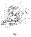
- Fig. 1 shows a combined miter, miter and pull saw.
- a chop saw with traction Prerequisite for the realization of the teaching of the invention, however, is only a chop saw with traction, with saw unit above the workpiece support surface of the carrier or below the workpiece support surface of the carrier. This has already been explained in the general part of the description.
- the chop saw shown initially has a carrier 1, which forms a workpiece support surface 2.
- the rear end of the workpiece support surface 2 here forms a stop rail 3, on which a workpiece, for example a wooden strip, can be applied.
- a holder 4 is mounted, which lies behind the back of the workpiece support surface 2.
- a saw unit 5 Attached to the holder 4 above the carrier 1 is a saw unit 5. In the illustrated and preferred exemplary embodiment, this is pivotable about a transverse axis 6 and is located above the workpiece support surface 2.
- the transverse axis would be omitted.
- the saw unit would be pulled here on tie rods that cantilever over the workpiece support surface.
- the saw unit 5 is about the transverse axis 6 from a raised rest position, the in Fig. 1 can be seen in a lowered sawing, which is not shown here, and pivoted the other way round.
- the saw unit 5 is biased towards the rest position, ie upwards, in particular by a spring. As a result, the saw unit 5, when you let go, returns by itself back to the raised rest position.
- the latter is a special feature of the chop saw, which does not always have to be realized, but is implemented in a particularly appropriate manner here.
- the chop saw shown has a miter function in addition to the previously described Kappfunktion. So it's already a crosscut and miter saw.
- the chop saw on the holder 4 in turn a tilt adjustment 15.
- the saw unit 5 can be compared to the carrier 1 to pivot about a direction of sawing, horizontal tilt pivot axis 16.
- Fig. 2 and 3 let recognize the position of the tilt pivot axis 16 on the holder 4.
- the inclination pivot axis 16 is physically at the specified location.
- a backdrop-like design is possible in which the inclination pivot axis 16 is only geometrically present and the pivoting movement is realized about this virtual pivot axis via other means of construction.
- an angle scale 17 at which one can read off the set angle of inclination. Due to the inclination about the inclination pivot axis 16, the miter angle of the executed saw cut can be adjusted and read off the angle scale 17.
- the illustrated and preferred chop saw has not only a cap function and a miter function, it also has a traction function.
- the saw unit 5 is pivotally mounted on the holder 4 not only by means of the transverse axis 6, but additionally also by means of a Switzerlandfiihrung extending in the sawing direction 18 of two mutually parallel tie rods 18a, b slidably mounted. With this pull function, the saw cut 5 can be extended by the saw unit 5.
- the illustrated and preferred embodiment shows on the support 1 a recessed turntable 19 with a forwardly projecting boom 20 and with a dipping slot 21 into which enters the sawing edge of the saw blade 10.
- the length of the immersion slit 21 is substantially greater than that required for the diameter of the saw blade 10. This is due to the above-described Buchfiihrung 18, which also allows just pulling the saw blade 10 through the workpiece over a certain path.
- Fig. 1 can be seen further that two mutually parallel tie rods 18a, 18b form the Glasfiihrung 18 and are rearwardly connected by a spacer 22 firmly together.
- the tie rods 18a, 18b are fixedly connected to the saw unit 5 and run on the holder 4 in Fig. 2 and 3 recognizable guides 23a, 23b.
- Fig. 2 shows the holder 4 of the preferred embodiment of a chop saw with traction with the two guides 23a, 23b.
- Fig. 3 shows that in the one guide 23a, a corresponding drawbar 18a, which is not shown here, practically free of play leading slide 24 is inserted in register.
- This sliding guide 24 is a ball bush in the preferred embodiment. But it can also be a different kind of leadership.
- a sliding guide 25 which is used with game.
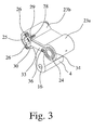
- Fig. 3 indicates that this slide 25 by means of at least one fixing element 26, in particular a fixing screw, in relation to the guide 23b radially different positions on the holder can be fixed.
- This in Fig. 2 and 3 illustrated embodiment leaves in Fig. 2 above and below the other guide 23b each recognize a threaded bore 27 and points in Fig. 3 , as here above and below the sliding guide 25, the two fixing elements 26 (fixing screws) are positioned.
- the sliding guide 25 in the other guide 23b actually designed as a genuine sliding bush, so not as a ball bushing.
- a ball bush carries much more in the thickness and can not be adjusted as well as a pure sliding bush.
- FIG. 2 and Fig. 3 illustrated embodiment shows yet another peculiarity of this construction, namely that the slide bush in turn fixed by the fixing member 26 position in turn at least partially again with an adjusting element 28, in particular an adjusting screw, is radially readjustable.
- the adjusting element 28 is arranged in a recess 29 of the holder 4.
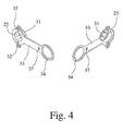
- Fig. 3 indicates that the adjustment screw 28 forming the adjustment screw screwed in an abutment nut inserted laterally in the recess 29 is located. If here the adjusting element 28 forming adjustment screw tightened, so is the in Fig. 4 recognizable divided tab 31 of the slide 25 is pressed inwards and pressed against the running in the guide 23b pull rod 18b. This allows you to adjust the draw resistance of the cable guide 18. In addition, a wear-related adjustment of this slide 25 is guaranteed.
- Fig. 2 and 3 let recognize another particularity of the construction according to the invention, which is characterized in that the sliding guide 24 is formed on the other guide 23b on a pivot lever 33 which is arranged on a flat side of the holder 4 and up to the slide 24 at the one guide 23a extends and is pivotally mounted there.
- This pivot lever 33 thus represents a spacer for the lateral spacing of the two tie rods 18a, 18b.
- the slide guide 25 is part of the pivoting lever 33rd
- the sliding guide 24 on one guide 23a protrudes from the holder 4 to the flat side and forms a pivot axis for a pivot bearing ring 34 of the pivot lever 33.
- the slots 32 are formed for the fixing elements 26 on the pivot lever 33 above and below the sliding guide 25.
- the pivot bearing ring 34 forms with the protruding part of the sliding guide 24 on the one guide 23a, the pivot bearing for the pivot lever 33. Accordingly, the slots 32 have expediently this arc radius corresponding arcuate course.
- Fig. 2 to 4 also belong to the right of the sliding guide 24 is still a threaded bore 35.
- fastener 36 is associated with a substantially circular arc extending slot 37 in the pivot lever 33, which in Fig. 4 recognizes very well.
- the pivot lever 33 is executed in the illustrated and preferred embodiment is particularly flat and wide. That's not exactly how it is done. Namely, it is provided that the pivot lever 33 rests flat on the flat side of the holder 4 and so wide is formed so that it covers all gaps on the guides 23a, 23b and protects against dust entry. Thus, the pivot lever 33, which is arranged yes as the saw unit 11 facing side of the holder 4, additionally fulfills the function of a dust cover or dust seal.
- the pivot lever 33 may suitably consist of a plastic material, in particular a fiber-reinforced plastic material.
- a plastic material comes into question, which also has in the region of the sliding guide 25 particularly good sliding properties. This can be achieved by adding appropriate additives or by coating on the appropriate surfaces.
Landscapes
- Engineering & Computer Science (AREA)
- General Engineering & Computer Science (AREA)
- Mechanical Engineering (AREA)
- Sawing (AREA)
Abstract
Description
Die Erfindung betrifft eine Kappsäge mit Zugfunktion mit den Merkmalen des Oberbegriffs von Anspruch 1.The invention relates to a chop saw with traction function with the features of the preamble of
Kappsägen der in Rede stehenden Art sind seit Jahrzehnten bekannt (
Eine typische Kappsäge hat ein um eine Querachse schwenkbar angebrachtes Sägeaggregat, dessen Sägeblatt aus einer angehobenen Ruhestellung in eine abgesenkte Sägestellung und umgekehrt schwenkbar ist. Mit dieser Bewegung des Sägeblattes kann ein auf einer Werkstückauflagefläche eines Trägers befindliches Werkstück abgeschnitten - gekappt - werden.A typical chop saw has a saw unit mounted pivotably about a transverse axis, the saw blade of which is pivotable from a raised rest position into a lowered saw position and vice versa. With this movement of the saw blade, a workpiece located on a workpiece support surface of a support can be cut off - cut off -.
Kappsägen sind aber nicht nur mit um eine Querachse schwenkbar angebrachtem Sägeaggregat bekannt, sondern auch mit einem in Längsrichtung über die Werkstückauflagefläche ziehbaren Sägeaggregat als sog. Radialarmsägen.However, chop saws are known not only with a saw unit mounted pivotably about a transverse axis, but also with a saw unit which can be pulled over the workpiece support surface in the longitudinal direction as so-called radial saws.
Kappsägen sind schließlich auch in Form von Tischkreissägen mit in Längsrichtung verschiebbaren Sägeaggregat, das unter der Werkstückauflagefläche des Trägers sitzt, bekannt.Finally, chop saws are also known in the form of table saws with a longitudinally displaceable saw unit, which sits under the workpiece support surface of the carrier.
Die bekannte Kappsäge, von der die Erfindung ausgeht (
Bei der bekannten Kappsäge ist das Sägeaggregat mittels einer Halterung am Träger angebracht. Bei der Kappfunktion wird das Sägeaggregat um eine Querachse aus der angehobenen Ruhestellung in die abgesenkte Sägestellung und umgekehrt geschwenkt.In the known chop saw the saw unit is mounted by means of a bracket on the carrier. When Kappfunktion the saw unit is pivoted about a transverse axis from the raised rest position in the lowered sawing position and vice versa.
An der Halterung, meist zwischen Halterung und Träger, ist hier im übrigen eine Neigungsverstellung vorgesehen. Die Neigungsverstellung dient dazu, das Sägeaggregat gegenüber dem Träger um eine in Sägerichtung verlaufende horizontale Schwenkachse schwenken zu können, um eben einen Gehrungsschnitt in gewünschtem Gehrungswinkel ausführen zu können. Dazu hat die Neigungsverstellung eine Neigungs-Schwenkachse.On the holder, usually between the holder and the carrier, a tilt adjustment is provided here, moreover. The tilt adjustment is used to pivot the saw unit relative to the carrier to a horizontal axis of rotation extending in the sawing direction, just to perform a miter cut in the desired miter angle can. For this purpose, the tilt adjustment has a tilt swivel axis.
Bei der bekannten Kappsäge ist auch eine Staubabsaugung am Sägeaggregat vorgesehen. Dazu befindet sich an der Kappsäge ein Absaugstutzen. An diesem kann ein Absaugschlauch oder ein Staubfangsack einer Staubfangvorrichtung angeschlossen werden.In the known chop saw and a dust extraction on the saw unit is provided. This is located on the chop saw a suction. On this a suction hose or a dust bag of a dust catcher can be connected.
Im Zusammenspiel der Neigungsverstellung einerseits und der Zugfiihrung andererseits muß man erreichen, daß das Kreissägeblatt des Sägeaggregates in Mittelstellung (Neigung 0°) exakt senkrecht zur Werkstückauflagefläche ausgerichtet ist. Gleichzeitig sollen die Zugstangen in den zueinander parallelen Führungen der Halterung möglichst leicht laufend, jedoch möglichst spielfrei gelagert sein. Das alles steht noch unter der Randbedingung, daß im Betrieb trotz vorhandener Staubabsaugung einiges an Sägestaub anfällt.In the interaction of the inclination adjustment on the one hand and the Zugfiihrung on the other hand one must ensure that the circular saw blade of the saw unit is aligned in the middle position (inclination 0 °) exactly perpendicular to the workpiece support surface. At the same time the tie rods in the mutually parallel guides of the holder as easily as possible running, but should be stored as free of play. All this is still under the boundary condition that accumulates in the operation despite existing dust extraction a lot of sawdust.
Es hat sich gezeigt, daß in der Praxis das richtige Einstellen der Position des Kreissägeblattes bei allen Arten von Kappsägen mit Zugfunktion ziemlich schwierig ist.It has been found that in practice the correct setting of the position of the circular saw blade is quite difficult in all types of traction cut-off saws.
Der Lehre liegt das Problem zugrunde, die Einstellung der Position des Sägeblattes bei einer Kappsäge mit Zugfunktion zu vereinfachen.The teaching is based on the problem of simplifying the adjustment of the position of the saw blade in a chop saw with traction function.
Die zuvor aufgezeigte Problemstellung ist bei einer Kappsäge mit den Merkmalen des Oberbegriffs von Anspruch 1 durch die Merkmale des kennzeichnenden Teils von Anspruch 1 gelöst. Bevorzugte Ausgestaltungen und Weiterbildungen sind Gegenstand der Unteransprüche.The above-indicated problem is solved in a chop saw with the features of the preamble of
Erfindungsgemäß wird eine Zugstange in einer Führung praktisch spielfrei in einer Gleitführung geführt, die ihrerseits paßgenau in der Führung eingesetzt ist. Eine solche praktisch spielfrei führende Gleitführung kann insbesondere als Kugelbuchse ausgeführt sein. Demgegenüber ist die die andere Zugstange führende Führung mit einer Gleitführung ausgerüstet, die mit Spiel in diese Führung eingesetzt ist. Diese Gleitführung kann man also innerhalb der Führung geringfügig verlagern und mittels mindestens eines Fixierelementes, vorzugsweise zweier Fixierelemente, relativ zur Führung in radial unterschiedlichen Positionen an der Halterung fixieren. Damit läßt sich die geringfügige Korrektur der Neigung des Kreissägeblattes realisieren, die für eine optimale Ausrichtung gegenüber der Werkstückauflagefläche erforderlich ist.According to the invention, a pull rod is guided in a guide virtually free of play in a sliding guide, which in turn is inserted in register in the guide. Such a virtually play-free leading sliding guide can in particular as a ball bushing be executed. In contrast, the leading the other drawbar guide is equipped with a sliding guide, which is used with play in this guide. This sliding guide can thus be slightly displaced within the guide and fixed by means of at least one fixing element, preferably two fixing elements, relative to the guide in radially different positions on the holder. Thus, the slight correction of the inclination of the circular saw blade can be realized, which is required for optimum alignment with respect to the workpiece support surface.
Grundsätzlich könnte auch die in der anderen Führung mit Spiel eingesetzte Gleitführung als Kugelbuchse ausgeführt sein. Hier hat es sich allerdings erwiesen, daß eine Gleitbuchse eine bessere Problemlösung schafft.In principle, the slide used in the other guide with game could be designed as a ball bushing. Here, however, it has been found that a sliding bushing creates a better problem solution.
Besonders bevorzugt ist eine Konstruktion, bei der die mit Spiel eingesetzte und mittels des Fixierelementes fixierbare Gleitbuchse in ihrer fixierten Position ihrerseits zumindest abschnittsweise nochmals mittels eines Justierelementes, insbesondere in Form einer Justierschraube, radial nachjustierbar ist. Durch dieses Justierelement ist dauerhafte Spielfreiheit der Zugstange in dieser Gleitführung gewährleistet, da bei evtl. Verschleiß mittels des Justierelementes die Gleitbuchse selbst abschnittsweise, beispielsweise mit einer Federlasche, nachgestellt werden kann. Darüber hinaus kann der Benutzer das Justierelement auch dazu verwenden, den Gleitwiderstand der Zugstange in dieser Führung zu verändern und individuell einzustellen.Particularly preferred is a construction in which the inserted with play and fixable by means of the fixing sliding bush in its fixed position in turn at least partially again by means of an adjusting element, in particular in the form of an adjusting screw, is radially readjusted. By this adjustment permanent freedom of the pull rod is guaranteed in this slide, since in case of wear by means of the adjusting element, the slide bush itself sections, for example with a spring tab, can be readjusted. In addition, the user can also use the adjusting element to change the sliding resistance of the drawbar in this guide and set individually.
Die Einstellung der mit Spiel eingesetzten Gleitführung an der anderen Führung gegenüber der Halterung läßt sich mit mindestens einem im wesentlichen radial verlaufenden Langloch für das Fixierelement verwirklichen. Bevorzugt sind zwei Langlöcher oberhalb und unterhalb der Gleitführung vorgesehen und es wird mit zwei Fixierelementen, insbesondere Fixierschrauben gearbeitet.The setting of the slide used with game on the other guide relative to the bracket can be realized with at least one substantially radially extending slot for the fixing. Preferably, two elongated holes are provided above and below the sliding guide and it is worked with two fixing elements, in particular fixing screws.
Von besonderer Bedeutung ist eine konstruktive Lösung, die die beiden Gleitfiihrungen in den Führungen der benachbarten Zugstangen miteinander verbindet. Dazu ist nach bevorzugter Lehre vorgesehen, daß die Gleitführung an der anderen Führung an einem Schwenkhebel ausgebildet ist, der auf einer Flachseite der Halterung angeordnet ist und sich bis zu der Gleitführung an der einen Führung erstreckt und dort schwenkbar gelagert ist. Insbesondere ist vorteilhaft, wenn die Gleitführung an der einen Führung, insbesondere also die Kugelbuchse, aus der Halterung zur Flachseite hin herausragt und eine Schwenkachse für einen Schwenklagerring des Schwenkhebels bildet.Of particular importance is a constructive solution that connects the two Gleitfiihrungen in the guides of the adjacent tie rods together. For this purpose, according to the preferred teaching that the sliding guide is formed on the other guide on a pivot lever which is arranged on a flat side of the bracket and extends to the sliding guide on a guide and is pivotally mounted there. In particular, it is advantageous if the Sliding guide on the one guide, in particular so the ball bushing, protrudes from the holder to the flat side and forms a pivot axis for a pivot bearing ring of the pivot lever.
Bei der zuvor erläuterten Konstruktion mit dem die Führungen verbindenden Schwenkhebel empfiehlt es sich natürlich, auch die Langlöcher in den Schwenkhebel zu integrieren.In the above-mentioned construction with the pivot lever connecting the guides, it is of course advisable to integrate the slots in the pivot lever.
Bevorzugte Ausgestaltungen des Schwenkhebels sind Gegenstand der weiteren Unteransprüche.Preferred embodiments of the pivot lever are the subject of the other dependent claims.
Besondere Bedeutung kommt dabei einer konstruktiven Lösung zu, die dadurch gekennzeichnet ist, daß der Schwenkhebel auf der Flachseite der Halterung flächig anliegt und so breit ausgebildet ist, daß er alle Spalte an den Führungen abdeckt und gegen Staubeintritt schützt. Hiermit erhält der Schwenkhebel eine weitere Funktion, nämlich die der Staubabdeckung der gefährdeten Spalten der Zugführung. Der Schwenkhebel beinhaltet dann drei Funktionen, die des seitlichen Abstandshalters, die der Gleitlagerung und die der Staubabdeckung. Durch diesen Schwenkhebel ist ein sehr einfaches und exaktes Einstellen der Lage des Sägeblattes möglich. Gemäß bevorzugter Konstruktion wird die ohnehin vorstehende Kugelbuchse ab der einen Führung gleichzeitig als Schwenklager des Schwenkhebels genutzt.Particular importance is attached to a constructive solution, which is characterized in that the pivot lever rests flat on the flat side of the holder and is so wide that it covers all gaps on the guides and protects against dust. This gives the pivot lever another function, namely the dust cover of the vulnerable columns of the cable guide. The pivot lever then includes three functions, the side spacer, the slide bearing and the dust cover. By this pivot lever a very simple and accurate adjustment of the position of the saw blade is possible. According to a preferred construction, the already projecting ball bushing is used from a guide at the same time as a pivot bearing of the pivot lever.
Im folgenden wir die Erfindung anhand einer lediglich ein Ausfiihrungsbeispiel darstellenden Zeichnung näher erläutert. Bei der Erläuterung der Zeichnung werden auch weitere Vorteile und Besonderheiten der Erfindung im Detail angesprochen und erläutert. In der Zeichnung zeigt
- Fig. 1
- in perspektivischer Darstellung ein Ausfiihrungsbeispiel einer erfindungsgemäßen Kappsäge,
- Fig. 2
- in perspektivischer Ansicht ein Ausfiihrungsbeispiel einer Halterung der Kappsäge aus
Fig. 1 , - Fig. 3
- in perspektivischer Ansicht die Halterung aus
Fig. 2 mit angesetztem Schwenkhebel und - Fig. 4
- den Schwenkhebel der Halterung aus
Fig. 3 in zwei unterschiedlichen perspektivischen Ansichten.
- Fig. 1
- 1 is a perspective view of an exemplary embodiment of a chop saw according to the invention,
- Fig. 2
- in a perspective view an exemplary embodiment of a holder of the chop saw
Fig. 1 . - Fig. 3
- in perspective view of the bracket
Fig. 2 with attached swivel lever and - Fig. 4
- the pivot lever of the bracket
Fig. 3 in two different perspective views.
Die in
An der Halterung 4 oberhalb des Trägers 1 angebracht ist ein Sägeaggregat 5. Dieses ist im dargestellten und bevorzugten Ausfiihrungsbeispiel um eine Querachse 6 schwenkbar und befindet sich oberhalb der Werkstückauflagefläche 2.Attached to the
Bei einer Radialarmsäge entfiele die Querachse. Das Sägeaggregat würde hier an Zugstangen gezogen, die auslegerartig über die Werkstückauflagefläche ragen.With a radial arm saw, the transverse axis would be omitted. The saw unit would be pulled here on tie rods that cantilever over the workpiece support surface.
Bei der dargestellten Kappsäge wird das Sägeaggregat 5 um die Querachse 6 aus einer angehobenen Ruhestellung, die in
Das Sägeaggregat 5 weist auf,
einen Betätigungshandgriff 7,einen Antriebsmotor 8ein vom Antriebsmotor 8 angetriebenes, auf einer Welle 9 gelagertes Sägeblatt 10,- eine das Sägeblatt 10 von oben her etwa über die Hälfte abdeckende feststehende Schutzhaube 11,
eine Pendelschutzhaube 12, die in der inFig. 1 dargestellten Ruhestellung den unteren Teil des Zahnkranzes des Sägeblattes 10 abdeckt,- einen Absaugstutzen 13 einer Staubfangvorrichtung und
- eine im Bereich zwischen der Halterung 4 und der Welle 9 unterhalb der feststehenden Schutzhaube 11 angeordnete bewegliche Staubfanghaube 14.
- an
operating handle 7, - a
drive motor 8 - a driven by the
drive motor 8, mounted on a shaft 9 saw blade 10, - a saw blade 10 from above about half covering the fixed
protective hood 11, - a
swing guard 12, which in the inFig. 1 shown rest position covers the lower part of the sprocket of the saw blade 10, - a suction nozzle 13 a dust catching device and
- a movable
dust collecting hood 14 arranged in the region between theholder 4 and the shaft 9 below the fixedprotective hood 11.
Letzteres ist eine besondere Ausstattung der Kappsäge, die nicht immer verwirklicht sein muß, aber in besonders zweckmäßiger Weise hier verwirklicht ist.The latter is a special feature of the chop saw, which does not always have to be realized, but is implemented in a particularly appropriate manner here.
Die dargestellte Kappsäge hat neben der zuvor bereits beschriebenen Kappfunktion eine Gehrungsfunktion. Es handelt sich also zunächst bereits um eine Kapp- und Gehrungssäge.The chop saw shown has a miter function in addition to the previously described Kappfunktion. So it's already a crosscut and miter saw.
Dazu weist die Kappsäge an der Halterung 4 ihrerseits eine Neigungsverstellung 15 auf. Mit der Neigungsverstellung 15 läßt sich das Sägeaggregat 5 gegenüber dem Träger 1 um eine in Sägerichtung verlaufende, horizontale Neigungs-Schwenkachse 16 schwenken.
Grundsätzlich ist auch eine kulissenartige Gestaltung möglich, bei der die Neigungs-Schwenkachse 16 nur geometrisch vorhanden ist und die Schwenkbewegung um diese virtuelle Schwenkachse über andere Konstruktionsmittel verwirklicht wird.Basically, a backdrop-like design is possible in which the
An der Neigungsverstellung 15 erkennt man in
Die dargestellte und bevorzugte Kappsäge hat jedoch nicht nur eine Kappfunktion und eine Gehrungsfunktion, sie hat auch eine Zugfunktion. Das Sägeaggregat 5 ist an der Halterung 4 nicht nur mittels der Querachse 6 schwenkbar gelagert, sondern zusätzlich auch noch mittels einer in Sägerichtung verlaufenden Zugfiihrung 18 aus zwei parallel zueinander verlaufenden Zugstangen 18a, b verschiebbar gelagert. Mit dieser Zugfunktion läßt sich der vom Sägeaggregat 5 ausfiihrbare Sägeschnitt verlängern.However, the illustrated and preferred chop saw has not only a cap function and a miter function, it also has a traction function. The
Das dargestellte und bevorzugte Ausführungsbeispiel zeigt am Träger 1 einen eingelassenen Drehteller 19 mit einem nach vorne vorspringenden Auslegerarm 20 und mit einem Eintauchschlitz 21, in den in Sägestellung der Rand des Sägeblattes 10 eintritt. Die Länge des Eintauchschlitzes 21 ist wesentlich größer als es für den Durchmesser des Sägeblattes 10 erforderlich ist. Das liegt an der zuvor erläuterten Zugfiihrung 18, die eben auch ein Ziehen des Sägeblattes 10 durch das Werkstück über einen bestimmten Weg erlaubt.The illustrated and preferred embodiment shows on the support 1 a recessed
In
Grundsätzlich ist auch eine kinematisch umgekehrte Anordnung mit feststehenden Zugstangen und darin mittels Führungen verschiebbar geführtem Sägeaggregat möglich. Das gilt auch, wenn keine Kappfunktion im engeren Sinne, sondern nur eine Zugfunktion (Radialarmsäge oder Tischkreissäge mit Zugfunktion) vorgesehen ist, die gleichzeitig die Kappfunktion erfüllt.In principle, a kinematically reversed arrangement with fixed tie rods and guided by means of guides slidably guided sawing unit is possible. This is true even if no cap function in the strict sense, but only a traction function (radial arm saw or table saw with traction function) is provided, which simultaneously fulfills the capping function.
In der anderen Führung 23b, deren zugeordnete Zugstange 18b ebenfalls nicht eingezeichnet ist, findet sich in
Im dargestellten und bevorzugten Ausführungsbeispiel ist die Gleitführung 25 in der anderen Führung 23b tatsächlich als echte Gleitbuchse, also nicht als Kugelbuchse ausgeführt. Eine Kugelbuchse trägt doch wesentlich stärker in der Dicke auf und läßt sich auch nicht so gut justieren wie eine reine Gleitbuchse.In the illustrated and preferred embodiment, the sliding
Das in
Zur Realisierung der Verstellbarkeit der Gleitführung 25 an der anderen Führung 23b sind hier oberhalb und unterhalb der Fixierelemente 26 zugeordnete Langlöcher 32 vorgesehen. Dadurch läßt sich dauerhaft die Relativlage der Gleitführung 25 zur zugeordneten Führung 23b im Rahmen des insgesamt vorhandenen Spiels einstellen. Dadurch läßt sich die Neigung des Sägeblattes gegenüber der Werkstückauflagefläche 2 einstellen.To realize the adjustability of the sliding
Im dargestellten und bevorzugten Ausführungsbeispiel ist dabei ferner vorgesehen, daß die Gleitführung 24 an der einen Führung 23a, insbesondere also die Kugelbuchse, aus der Halterung 4 zur Flachseite hin herausragt und eine Schwenkachse für einen Schwenklagerring 34 des Schwenkhebels 33 bildet. Im einzelnen ist hier vorgesehen, daß auch die Langlöcher 32 für die Fixierelemente 26 am Schwenkhebel 33 oberhalb und unterhalb der Gleitführung 25 ausgebildet sind. Dabei bildet der Schwenklagerring 34 mit dem vorstehenden Teil der Gleitführung 24 an der einen Führung 23a das Schwenklager für den Schwenkhebel 33. Dementsprechend haben die Langlöcher 32 zweckmäßigerweise einen diesen Schwenkradius entsprechenden bogenförmigen Verlauf.In the illustrated and preferred embodiment, it is further provided that the sliding
Auch dem Befestigungselement 36 ist ein im wesentlichen kreisbogenförmig verlaufendes Langloch 37 im Schwenkhebel 33 zugeordnet, das man in
Schließlich ist noch darauf hinzuweisen, daß der Schwenkhebel 33 zweckmäßigerweise aus einem Kunststoffmaterial, insbesondere einem faserverstärktem Kunststoffmaterial bestehen kann. Insbesondere kommt ein Kunststoffinaterial in Frage, das ebenfalls im Bereich der Gleitführung 25 besonders gute Gleiteigenschaften aufweist. Das kann man durch Beimischung entsprechender Zusätze oder durch eine Beschichtung an den entsprechenden Flächen erreichen.Finally, it should be pointed out that the
Claims (14)
einem Träger (1), der eine Werkstückauflagefläche (2) bildet,
einer am Träger (1) angebrachten Halterung (4) und
einem mittels der Halterung (4) angebrachten Sägeaggregat (5),
wobei das Sägeaggregat (5) an der Halterung (4) mittels einer in Sägerichtung verlaufenden Zugführung (18) aus zwei parallel zueinander verlaufenden Zugstangen (18a, 18b) verschiebbar gelagert ist und
wobei die Zugstangen (18a, 18b) an der Halterung (4) in zueinander parallelen Führungen (23a, b) verschiebbar gelagert sind,
dadurch gekennzeichnet,
daß in einer Führung (23a) eine die Zugstange (18a) praktisch spielfrei führende Gleitführung (24) paßgenau eingesetzt ist und
daß in der anderen Führung (23b) eine die Zugstange (18b) führende Gleitfiihrung (24) mit Spiel eingesetzt und mittels eines Fixierelementes (26), insbesondere einer Fixierschraube, in relativ zur Führung (23b) radial unterschiedlichen Positionen an der Halterung (4) fixierbar ist.Chop saw with
a carrier (1) forming a workpiece support surface (2),
a on the support (1) mounted bracket (4) and
a sawing unit (5) attached by means of the holder (4),
wherein the saw unit (5) is displaceably mounted on the holder (4) by means of a pull guide (18) running in sawing direction, comprising two tie rods (18a, 18b) extending parallel to one another and
wherein the tie rods (18a, 18b) are displaceably mounted on the holder (4) in mutually parallel guides (23a, b),
characterized,
that in a guide (23 a) a tie rod (18 a) practically free of play leading sliding guide (24) is inserted in register and
in that in the other guide (23b) a Gleitfiihrung (24) leading the tie rod (18b) used with play and by means of a fixing element (26), in particular a fixing screw, in radially different positions on the holder (4) relative to the guide (23b) can be fixed.
daß die Gleitführung (24) in der einen Führung (23a) als Kugelbuchse ausgeführt ist.Chop saw according to claim 1, characterized
that the sliding guide (24) in the one guide (23a) is designed as a ball bushing.
daß die Gleitführung (24) in der anderen Führung (23b) als Gleitbuchse ausgeführt ist.Chop saw according to claim 1 or 2, characterized
that the sliding guide (24) in the other guide (23b) is designed as a sliding bushing.
daß die Gleitbuchse in durch das Fixierelement (26) fixierter Position ihrerseits zumindest abschnittsweise nochmals mit einem Justierelement (28), insbesondere einer Justierschraube, radial nachjustierbar ist.Chop saw according to claim 3, characterized
in that the sliding bushing is at least in sections again radially adjustable in position fixed by the fixing element (26) with an adjusting element (28), in particular an adjusting screw.
daß das Justierelement (28) in einer Ausnehmung (29) der Halterung (4) angeordnet ist.Chop saw according to claim 4, characterized
in that the adjusting element (28) is arranged in a recess (29) of the holder (4).
daß die Gleitführung (24) an der anderen Führung (23b) mit mindestens einem im wesentlichen radial verlaufenden Langloch (32) für das Fixierelement (26) versehen ist.Chop saw according to one of claims 1 to 5, characterized
in that the sliding guide (24) is provided on the other guide (23b) with at least one substantially radially extending slot (32) for the fixing element (26).
daß die Gleitführung (24) an der anderen Führung (23b) an einem Schwenkhebel (33) ausgebildet ist, der auf einer Flachseite der Halterung (4) angeordnet ist und sich bis zu der Gleitführung (24) an der einen Führung (23a) erstreckt und dort schwenkbar gelagert ist.Chop saw according to one of claims 1 to 6, characterized
in that the sliding guide (24) on the other guide (23b) is formed on a pivoting lever (33) which is arranged on a flat side of the holder (4) and extends as far as the sliding guide (24) on the one guide (23a) and is pivotally mounted there.
daß die Gleitführung (24) an der einen Führung (23a), insbesondere also die Kugelbuchse, aus der Halterung (4) zur Flachseite hin herausragt und eine Schwenkachse für einen Schwenklagerring (34) des Schwenkhebels (33) bildet.Chop saw according to claim 7, characterized
in that the sliding guide (24) protrudes from the holder (4) towards the flat side on the one guide (23a), in particular therefore the ball bushing, and forms a pivot axis for a pivot bearing ring (34) of the pivot lever (33).
daß das mindestens eine Langloch (32) am Schwenkhebel (33) ausgebildet ist und, vorzugsweise, einen bogenförmigen Verlauf entsprechend dem Schwenkradius des Schwenkhebels (33) aufweist.Chop saw according to claim 7 or 8, characterized
in that the at least one slot (32) is formed on the pivoting lever (33) and, preferably, has an arcuate course corresponding to the pivoting radius of the pivoting lever (33).
daß nahe dem an der einen Führung (23a) angeordneten Ende des Schwenkhebels (33) ein Befestigungselement (36) zur Befestigung des Schwenkhebels (33) an der Halterung (4) vorgesehen ist.Chop saw according to one of claims 7 to 9, characterized
in that a fastening element (36) for fastening the pivoting lever (33) to the holder (4) is provided near the end of the pivoting lever (33) arranged on the one guide (23a).
daß das Befestigungselement (36) eine ein kreisbogenförmiges Langloch (32) im Schwenkhebel (33) durchsetzende Befestigungsschraube ist.Chop saw according to claim 10, characterized
in that the fastening element (36) is a fastening screw passing through an arcuate slot (32) in the pivoting lever (33).
daß der Schwenkhebel (33) auf der Flachseite der Halterung (4) flächig anliegt und so breit ausgebildet ist, daß er alle Spalte an den Führungen (23a, 23b) abdeckt und gegen Staubeintritt schützt.Chop saw according to one of claims 7 to 11, characterized
that the pivot lever (33) on the flat side of the holder (4) rests flat and is so wide that it covers all gaps on the guides (23a, 23b) and protects against dust entry.
daß der Schwenkhebel (33) auf der dem Sägeaggregat (5) zugewandten Seite der Halterung (4) angeordnet ist.Chop saw according to claim 12, characterized in that
in that the pivoting lever (33) is arranged on the side of the holder (4) facing the sawing unit (5).
daß der Schwenkhebel (33) aus einem vorzugsweise faserverstärktem Kunststoffinaterial besteht, daß, vorzugsweise, das Kunststoffmaterial jedenfalls im Bereich der Gleitführung (25) besonders gute Gleiteigenschaften aufweist.Chop saw according to one of claims 7 to 13, characterized
that the pivoting lever (33) consists of a preferably fiber-reinforced plastic material, that, preferably, the plastic material in any case in the region of the sliding guide (25) has particularly good sliding properties.
Applications Claiming Priority (1)
| Application Number | Priority Date | Filing Date | Title |
|---|---|---|---|
| DE202008011654U DE202008011654U1 (en) | 2008-09-02 | 2008-09-02 | Chop saw with pull function |
Publications (3)
| Publication Number | Publication Date |
|---|---|
| EP2158991A2 true EP2158991A2 (en) | 2010-03-03 |
| EP2158991A3 EP2158991A3 (en) | 2012-07-18 |
| EP2158991B1 EP2158991B1 (en) | 2018-01-24 |
Family
ID=41361301
Family Applications (1)
| Application Number | Title | Priority Date | Filing Date |
|---|---|---|---|
| EP09010096.7A Not-in-force EP2158991B1 (en) | 2008-09-02 | 2009-08-05 | Mitre saw with traction function |
Country Status (2)
| Country | Link |
|---|---|
| EP (1) | EP2158991B1 (en) |
| DE (1) | DE202008011654U1 (en) |
Families Citing this family (4)
| Publication number | Priority date | Publication date | Assignee | Title |
|---|---|---|---|---|
| DE102010062255A1 (en) | 2010-12-01 | 2012-06-06 | Robert Bosch Gmbh | chop saw |
| DE102013224128B3 (en) | 2013-11-26 | 2015-04-30 | Metabowerke Gmbh | Crosscut and saw |
| DE102021125710B3 (en) | 2021-10-04 | 2022-11-24 | Metabowerke Gmbh | Miter saw and pull saw |
| DE102024139220A1 (en) | 2024-12-20 | 2026-06-25 | Einhell Germany Ag | Machine tool and methods for setting, aligning and/or calibrating |
Citations (2)
| Publication number | Priority date | Publication date | Assignee | Title |
|---|---|---|---|---|
| DE20313885U1 (en) | 2002-09-26 | 2003-11-13 | Metabowerke GmbH, 72622 Nürtingen | Crosscut and miter saw with angle adjustment on a turntable |
| EP1557231A1 (en) | 2004-01-22 | 2005-07-27 | Metabowerke GmbH | Chop saw with dust catching device |
Family Cites Families (9)
| Publication number | Priority date | Publication date | Assignee | Title |
|---|---|---|---|---|
| JP3320950B2 (en) * | 1995-06-15 | 2002-09-03 | 株式会社マキタ | Support structure of slide bar on slide marunoco |
| US5819624A (en) * | 1996-07-30 | 1998-10-13 | Milwaukee Electric Tool Corporation | Indexing override mechanism for a slide compound miter saw |
| JP3549732B2 (en) * | 1997-07-23 | 2004-08-04 | 株式会社マキタ | Stopper device for slide mechanism |
| US7207251B2 (en) * | 1999-02-05 | 2007-04-24 | Hitachi Koki Co., Ltd. | Cutter with laser generator that irradiates cutting position on workpiece to facilitate alignment of blade with cutting position |
| US6918330B2 (en) * | 2000-10-24 | 2005-07-19 | Thomson Industries, Inc. | Adjustable tool station |
| US6901834B2 (en) * | 2003-09-26 | 2005-06-07 | Chin-Chin Chang | Movement adjust device for a circular saw |
| JP4534549B2 (en) * | 2004-03-26 | 2010-09-01 | 日立工機株式会社 | Tabletop cutting machine |
| JP2005279933A (en) * | 2004-03-26 | 2005-10-13 | Hitachi Koki Co Ltd | Tabletop cutting machine |
| TWI288037B (en) * | 2004-07-06 | 2007-10-11 | Hitachi Koki Kk | Miter saw having digital display |
-
2008
- 2008-09-02 DE DE202008011654U patent/DE202008011654U1/en not_active Expired - Lifetime
-
2009
- 2009-08-05 EP EP09010096.7A patent/EP2158991B1/en not_active Not-in-force
Patent Citations (2)
| Publication number | Priority date | Publication date | Assignee | Title |
|---|---|---|---|---|
| DE20313885U1 (en) | 2002-09-26 | 2003-11-13 | Metabowerke GmbH, 72622 Nürtingen | Crosscut and miter saw with angle adjustment on a turntable |
| EP1557231A1 (en) | 2004-01-22 | 2005-07-27 | Metabowerke GmbH | Chop saw with dust catching device |
Also Published As
| Publication number | Publication date |
|---|---|
| DE202008011654U1 (en) | 2010-01-21 |
| EP2158991B1 (en) | 2018-01-24 |
| EP2158991A3 (en) | 2012-07-18 |
Similar Documents
| Publication | Publication Date | Title |
|---|---|---|
| EP1557231B1 (en) | Chop saw with dust catching device | |
| EP0163186B1 (en) | Jig saw for working work pieces, for example those of wood, plastic or metal | |
| EP2158991B1 (en) | Mitre saw with traction function | |
| DE3718232C2 (en) | ||
| EP2250005B1 (en) | Circular saw with adjustable angle control | |
| EP2241396B1 (en) | Machine tool, in particular mitre saw. | |
| EP1839791B1 (en) | Circular saw bench | |
| DE2133308C3 (en) | Electric circular saw | |
| DE3447933A1 (en) | Compass saw for machining workpieces, for example of wood, plastics or metal | |
| DE202008001743U1 (en) | Chop saw with a dust extraction and / or a fairing | |
| EP2250006B1 (en) | Circular saw with adjustable inclination | |
| EP2249989B1 (en) | Circular saw provided with a cutting depth stop | |
| EP2241422B1 (en) | Mitre saw with angle adjustment | |
| DE202006012601U1 (en) | Saw for capping and beveling has at leat one auxiliary carrier extending round workpiece resting surface on carrier sectors | |
| DE20100087U1 (en) | Circular saw | |
| DE202006012418U1 (en) | Powered capping and miter saw for e.g. sheet metal or wood has turntable base with twin internal lock | |
| DE19515829C2 (en) | Saw, especially circular saw with a table | |
| DE2910337C2 (en) | Combined table and mitre saw | |
| EP2277674B1 (en) | Machine tool, in particular saw | |
| DE202006012341U1 (en) | Capped saw for cutting all types of materials, especially plastic and metal, comprises an adjustable stop arranged on a saw arrangement in the longitudinal direction at a distance from a pivoting bearing | |
| DE7905808U1 (en) | COMBINED TABLE AND CUTTING CIRCULAR SAW | |
| EP1518628A1 (en) | Chop saw, in particular for wood working | |
| DE20210223U1 (en) | Holding device for chainsaw, especially for chainsaw | |
| EP2186588B1 (en) | Chop and mitre-box saw | |
| EP2216148A1 (en) | Mitre saw |
Legal Events
| Date | Code | Title | Description |
|---|---|---|---|
| PUAI | Public reference made under article 153(3) epc to a published international application that has entered the european phase |
Free format text: ORIGINAL CODE: 0009012 |
|
| AK | Designated contracting states |
Kind code of ref document: A2 Designated state(s): AT BE BG CH CY CZ DE DK EE ES FI FR GB GR HR HU IE IS IT LI LT LU LV MC MK MT NL NO PL PT RO SE SI SK SM TR |
|
| AX | Request for extension of the european patent |
Extension state: AL BA RS |
|
| PUAL | Search report despatched |
Free format text: ORIGINAL CODE: 0009013 |
|
| AK | Designated contracting states |
Kind code of ref document: A3 Designated state(s): AT BE BG CH CY CZ DE DK EE ES FI FR GB GR HR HU IE IS IT LI LT LU LV MC MK MT NL NO PL PT RO SE SI SK SM TR |
|
| AX | Request for extension of the european patent |
Extension state: AL BA RS |
|
| RIC1 | Information provided on ipc code assigned before grant |
Ipc: F16C 29/00 20060101ALI20120611BHEP Ipc: B23D 45/04 20060101AFI20120611BHEP Ipc: B23D 47/02 20060101ALI20120611BHEP |
|
| 17P | Request for examination filed |
Effective date: 20120911 |
|
| GRAP | Despatch of communication of intention to grant a patent |
Free format text: ORIGINAL CODE: EPIDOSNIGR1 |
|
| INTG | Intention to grant announced |
Effective date: 20171018 |
|
| GRAS | Grant fee paid |
Free format text: ORIGINAL CODE: EPIDOSNIGR3 |
|
| GRAA | (expected) grant |
Free format text: ORIGINAL CODE: 0009210 |
|
| AK | Designated contracting states |
Kind code of ref document: B1 Designated state(s): AT BE BG CH CY CZ DE DK EE ES FI FR GB GR HR HU IE IS IT LI LT LU LV MC MK MT NL NO PL PT RO SE SI SK SM TR |
|
| REG | Reference to a national code |
Ref country code: GB Ref legal event code: FG4D Free format text: NOT ENGLISH |
|
| REG | Reference to a national code |
Ref country code: CH Ref legal event code: EP |
|
| REG | Reference to a national code |
Ref country code: AT Ref legal event code: REF Ref document number: 965504 Country of ref document: AT Kind code of ref document: T Effective date: 20180215 |
|
| REG | Reference to a national code |
Ref country code: IE Ref legal event code: FG4D Free format text: LANGUAGE OF EP DOCUMENT: GERMAN |
|
| REG | Reference to a national code |
Ref country code: DE Ref legal event code: R096 Ref document number: 502009014694 Country of ref document: DE |
|
| REG | Reference to a national code |
Ref country code: NL Ref legal event code: MP Effective date: 20180124 |
|
| REG | Reference to a national code |
Ref country code: LT Ref legal event code: MG4D |
|
| PG25 | Lapsed in a contracting state [announced via postgrant information from national office to epo] |
Ref country code: NL Free format text: LAPSE BECAUSE OF FAILURE TO SUBMIT A TRANSLATION OF THE DESCRIPTION OR TO PAY THE FEE WITHIN THE PRESCRIBED TIME-LIMIT Effective date: 20180124 |
|
| PG25 | Lapsed in a contracting state [announced via postgrant information from national office to epo] |
Ref country code: HR Free format text: LAPSE BECAUSE OF FAILURE TO SUBMIT A TRANSLATION OF THE DESCRIPTION OR TO PAY THE FEE WITHIN THE PRESCRIBED TIME-LIMIT Effective date: 20180124 Ref country code: CY Free format text: LAPSE BECAUSE OF FAILURE TO SUBMIT A TRANSLATION OF THE DESCRIPTION OR TO PAY THE FEE WITHIN THE PRESCRIBED TIME-LIMIT Effective date: 20180124 Ref country code: FI Free format text: LAPSE BECAUSE OF FAILURE TO SUBMIT A TRANSLATION OF THE DESCRIPTION OR TO PAY THE FEE WITHIN THE PRESCRIBED TIME-LIMIT Effective date: 20180124 Ref country code: NO Free format text: LAPSE BECAUSE OF FAILURE TO SUBMIT A TRANSLATION OF THE DESCRIPTION OR TO PAY THE FEE WITHIN THE PRESCRIBED TIME-LIMIT Effective date: 20180424 Ref country code: ES Free format text: LAPSE BECAUSE OF FAILURE TO SUBMIT A TRANSLATION OF THE DESCRIPTION OR TO PAY THE FEE WITHIN THE PRESCRIBED TIME-LIMIT Effective date: 20180124 Ref country code: LT Free format text: LAPSE BECAUSE OF FAILURE TO SUBMIT A TRANSLATION OF THE DESCRIPTION OR TO PAY THE FEE WITHIN THE PRESCRIBED TIME-LIMIT Effective date: 20180124 |
|
| REG | Reference to a national code |
Ref country code: FR Ref legal event code: PLFP Year of fee payment: 10 |
|
| PG25 | Lapsed in a contracting state [announced via postgrant information from national office to epo] |
Ref country code: LV Free format text: LAPSE BECAUSE OF FAILURE TO SUBMIT A TRANSLATION OF THE DESCRIPTION OR TO PAY THE FEE WITHIN THE PRESCRIBED TIME-LIMIT Effective date: 20180124 Ref country code: SE Free format text: LAPSE BECAUSE OF FAILURE TO SUBMIT A TRANSLATION OF THE DESCRIPTION OR TO PAY THE FEE WITHIN THE PRESCRIBED TIME-LIMIT Effective date: 20180124 Ref country code: BG Free format text: LAPSE BECAUSE OF FAILURE TO SUBMIT A TRANSLATION OF THE DESCRIPTION OR TO PAY THE FEE WITHIN THE PRESCRIBED TIME-LIMIT Effective date: 20180424 Ref country code: GR Free format text: LAPSE BECAUSE OF FAILURE TO SUBMIT A TRANSLATION OF THE DESCRIPTION OR TO PAY THE FEE WITHIN THE PRESCRIBED TIME-LIMIT Effective date: 20180425 Ref country code: IS Free format text: LAPSE BECAUSE OF FAILURE TO SUBMIT A TRANSLATION OF THE DESCRIPTION OR TO PAY THE FEE WITHIN THE PRESCRIBED TIME-LIMIT Effective date: 20180524 Ref country code: PL Free format text: LAPSE BECAUSE OF FAILURE TO SUBMIT A TRANSLATION OF THE DESCRIPTION OR TO PAY THE FEE WITHIN THE PRESCRIBED TIME-LIMIT Effective date: 20180124 |
|
| PG25 | Lapsed in a contracting state [announced via postgrant information from national office to epo] |
Ref country code: MT Free format text: LAPSE BECAUSE OF FAILURE TO SUBMIT A TRANSLATION OF THE DESCRIPTION OR TO PAY THE FEE WITHIN THE PRESCRIBED TIME-LIMIT Effective date: 20180124 |
|
| REG | Reference to a national code |
Ref country code: DE Ref legal event code: R097 Ref document number: 502009014694 Country of ref document: DE |
|
| PG25 | Lapsed in a contracting state [announced via postgrant information from national office to epo] |
Ref country code: IT Free format text: LAPSE BECAUSE OF FAILURE TO SUBMIT A TRANSLATION OF THE DESCRIPTION OR TO PAY THE FEE WITHIN THE PRESCRIBED TIME-LIMIT Effective date: 20180124 Ref country code: RO Free format text: LAPSE BECAUSE OF FAILURE TO SUBMIT A TRANSLATION OF THE DESCRIPTION OR TO PAY THE FEE WITHIN THE PRESCRIBED TIME-LIMIT Effective date: 20180124 Ref country code: EE Free format text: LAPSE BECAUSE OF FAILURE TO SUBMIT A TRANSLATION OF THE DESCRIPTION OR TO PAY THE FEE WITHIN THE PRESCRIBED TIME-LIMIT Effective date: 20180124 |
|
| PG25 | Lapsed in a contracting state [announced via postgrant information from national office to epo] |
Ref country code: SM Free format text: LAPSE BECAUSE OF FAILURE TO SUBMIT A TRANSLATION OF THE DESCRIPTION OR TO PAY THE FEE WITHIN THE PRESCRIBED TIME-LIMIT Effective date: 20180124 Ref country code: DK Free format text: LAPSE BECAUSE OF FAILURE TO SUBMIT A TRANSLATION OF THE DESCRIPTION OR TO PAY THE FEE WITHIN THE PRESCRIBED TIME-LIMIT Effective date: 20180124 Ref country code: SK Free format text: LAPSE BECAUSE OF FAILURE TO SUBMIT A TRANSLATION OF THE DESCRIPTION OR TO PAY THE FEE WITHIN THE PRESCRIBED TIME-LIMIT Effective date: 20180124 Ref country code: CZ Free format text: LAPSE BECAUSE OF FAILURE TO SUBMIT A TRANSLATION OF THE DESCRIPTION OR TO PAY THE FEE WITHIN THE PRESCRIBED TIME-LIMIT Effective date: 20180124 |
|
| PLBE | No opposition filed within time limit |
Free format text: ORIGINAL CODE: 0009261 |
|
| STAA | Information on the status of an ep patent application or granted ep patent |
Free format text: STATUS: NO OPPOSITION FILED WITHIN TIME LIMIT |
|
| 26N | No opposition filed |
Effective date: 20181025 |
|
| PG25 | Lapsed in a contracting state [announced via postgrant information from national office to epo] |
Ref country code: SI Free format text: LAPSE BECAUSE OF FAILURE TO SUBMIT A TRANSLATION OF THE DESCRIPTION OR TO PAY THE FEE WITHIN THE PRESCRIBED TIME-LIMIT Effective date: 20180124 |
|
| PG25 | Lapsed in a contracting state [announced via postgrant information from national office to epo] |
Ref country code: MC Free format text: LAPSE BECAUSE OF FAILURE TO SUBMIT A TRANSLATION OF THE DESCRIPTION OR TO PAY THE FEE WITHIN THE PRESCRIBED TIME-LIMIT Effective date: 20180124 |
|
| REG | Reference to a national code |
Ref country code: CH Ref legal event code: PL |
|
| PG25 | Lapsed in a contracting state [announced via postgrant information from national office to epo] |
Ref country code: LU Free format text: LAPSE BECAUSE OF NON-PAYMENT OF DUE FEES Effective date: 20180805 Ref country code: LI Free format text: LAPSE BECAUSE OF NON-PAYMENT OF DUE FEES Effective date: 20180831 Ref country code: CH Free format text: LAPSE BECAUSE OF NON-PAYMENT OF DUE FEES Effective date: 20180831 |
|
| REG | Reference to a national code |
Ref country code: BE Ref legal event code: MM Effective date: 20180831 |
|
| REG | Reference to a national code |
Ref country code: IE Ref legal event code: MM4A |
|
| PG25 | Lapsed in a contracting state [announced via postgrant information from national office to epo] |
Ref country code: IE Free format text: LAPSE BECAUSE OF NON-PAYMENT OF DUE FEES Effective date: 20180805 |
|
| PG25 | Lapsed in a contracting state [announced via postgrant information from national office to epo] |
Ref country code: BE Free format text: LAPSE BECAUSE OF NON-PAYMENT OF DUE FEES Effective date: 20180831 |
|
| REG | Reference to a national code |
Ref country code: AT Ref legal event code: MM01 Ref document number: 965504 Country of ref document: AT Kind code of ref document: T Effective date: 20180805 |
|
| PG25 | Lapsed in a contracting state [announced via postgrant information from national office to epo] |
Ref country code: AT Free format text: LAPSE BECAUSE OF NON-PAYMENT OF DUE FEES Effective date: 20180805 |
|
| PG25 | Lapsed in a contracting state [announced via postgrant information from national office to epo] |
Ref country code: TR Free format text: LAPSE BECAUSE OF FAILURE TO SUBMIT A TRANSLATION OF THE DESCRIPTION OR TO PAY THE FEE WITHIN THE PRESCRIBED TIME-LIMIT Effective date: 20180124 |
|
| PG25 | Lapsed in a contracting state [announced via postgrant information from national office to epo] |
Ref country code: HU Free format text: LAPSE BECAUSE OF FAILURE TO SUBMIT A TRANSLATION OF THE DESCRIPTION OR TO PAY THE FEE WITHIN THE PRESCRIBED TIME-LIMIT; INVALID AB INITIO Effective date: 20090805 Ref country code: PT Free format text: LAPSE BECAUSE OF FAILURE TO SUBMIT A TRANSLATION OF THE DESCRIPTION OR TO PAY THE FEE WITHIN THE PRESCRIBED TIME-LIMIT Effective date: 20180124 |
|
| PG25 | Lapsed in a contracting state [announced via postgrant information from national office to epo] |
Ref country code: MK Free format text: LAPSE BECAUSE OF NON-PAYMENT OF DUE FEES Effective date: 20180124 |
|
| PGFP | Annual fee paid to national office [announced via postgrant information from national office to epo] |
Ref country code: FR Payment date: 20200820 Year of fee payment: 12 Ref country code: GB Payment date: 20200825 Year of fee payment: 12 |
|
| GBPC | Gb: european patent ceased through non-payment of renewal fee |
Effective date: 20210805 |
|
| PG25 | Lapsed in a contracting state [announced via postgrant information from national office to epo] |
Ref country code: GB Free format text: LAPSE BECAUSE OF NON-PAYMENT OF DUE FEES Effective date: 20210805 Ref country code: FR Free format text: LAPSE BECAUSE OF NON-PAYMENT OF DUE FEES Effective date: 20210831 |
|
| PGFP | Annual fee paid to national office [announced via postgrant information from national office to epo] |
Ref country code: DE Payment date: 20240819 Year of fee payment: 16 |
|
| REG | Reference to a national code |
Ref country code: DE Ref legal event code: R119 Ref document number: 502009014694 Country of ref document: DE |
|
| PG25 | Lapsed in a contracting state [announced via postgrant information from national office to epo] |
Ref country code: DE Free format text: LAPSE BECAUSE OF NON-PAYMENT OF DUE FEES Effective date: 20260303 |