EP2158991A2 - Scie circulaire dotée d'une fonction de traction - Google Patents
Scie circulaire dotée d'une fonction de traction Download PDFInfo
- Publication number
- EP2158991A2 EP2158991A2 EP09010096A EP09010096A EP2158991A2 EP 2158991 A2 EP2158991 A2 EP 2158991A2 EP 09010096 A EP09010096 A EP 09010096A EP 09010096 A EP09010096 A EP 09010096A EP 2158991 A2 EP2158991 A2 EP 2158991A2
- Authority
- EP
- European Patent Office
- Prior art keywords
- guide
- holder
- chop saw
- saw according
- sliding
- Prior art date
- Legal status (The legal status is an assumption and is not a legal conclusion. Google has not performed a legal analysis and makes no representation as to the accuracy of the status listed.)
- Granted
Links
Images

Classifications
-
- B—PERFORMING OPERATIONS; TRANSPORTING
- B23—MACHINE TOOLS; METAL-WORKING NOT OTHERWISE PROVIDED FOR
- B23D—PLANING; SLOTTING; SHEARING; BROACHING; SAWING; FILING; SCRAPING; LIKE OPERATIONS FOR WORKING METAL BY REMOVING MATERIAL, NOT OTHERWISE PROVIDED FOR
- B23D47/00—Sawing machines or sawing devices working with circular saw blades, characterised only by constructional features of particular parts
- B23D47/02—Sawing machines or sawing devices working with circular saw blades, characterised only by constructional features of particular parts of frames; of guiding arrangements for work-table or saw-carrier
-
- B—PERFORMING OPERATIONS; TRANSPORTING
- B23—MACHINE TOOLS; METAL-WORKING NOT OTHERWISE PROVIDED FOR
- B23D—PLANING; SLOTTING; SHEARING; BROACHING; SAWING; FILING; SCRAPING; LIKE OPERATIONS FOR WORKING METAL BY REMOVING MATERIAL, NOT OTHERWISE PROVIDED FOR
- B23D45/00—Sawing machines or sawing devices with circular saw blades or with friction saw discs
- B23D45/04—Sawing machines or sawing devices with circular saw blades or with friction saw discs with a circular saw blade or the stock carried by a pivoted lever
- B23D45/042—Sawing machines or sawing devices with circular saw blades or with friction saw discs with a circular saw blade or the stock carried by a pivoted lever with the saw blade carried by a pivoted lever
- B23D45/046—Sawing machines or sawing devices with circular saw blades or with friction saw discs with a circular saw blade or the stock carried by a pivoted lever with the saw blade carried by a pivoted lever the pivoted lever being mounted on a carriage
- B23D45/048—Sawing machines or sawing devices with circular saw blades or with friction saw discs with a circular saw blade or the stock carried by a pivoted lever with the saw blade carried by a pivoted lever the pivoted lever being mounted on a carriage the saw blade being adjustable according to angle of cut
-
- F—MECHANICAL ENGINEERING; LIGHTING; HEATING; WEAPONS; BLASTING
- F16—ENGINEERING ELEMENTS AND UNITS; GENERAL MEASURES FOR PRODUCING AND MAINTAINING EFFECTIVE FUNCTIONING OF MACHINES OR INSTALLATIONS; THERMAL INSULATION IN GENERAL
- F16C—SHAFTS; FLEXIBLE SHAFTS; ELEMENTS OR CRANKSHAFT MECHANISMS; ROTARY BODIES OTHER THAN GEARING ELEMENTS; BEARINGS
- F16C29/00—Bearings for parts moving only linearly
- F16C29/001—Bearings for parts moving only linearly adjustable for alignment or positioning
-
- F—MECHANICAL ENGINEERING; LIGHTING; HEATING; WEAPONS; BLASTING
- F16—ENGINEERING ELEMENTS AND UNITS; GENERAL MEASURES FOR PRODUCING AND MAINTAINING EFFECTIVE FUNCTIONING OF MACHINES OR INSTALLATIONS; THERMAL INSULATION IN GENERAL
- F16C—SHAFTS; FLEXIBLE SHAFTS; ELEMENTS OR CRANKSHAFT MECHANISMS; ROTARY BODIES OTHER THAN GEARING ELEMENTS; BEARINGS
- F16C29/00—Bearings for parts moving only linearly
- F16C29/008—Systems with a plurality of bearings, e.g. four carriages supporting a slide on two parallel rails
-
- F—MECHANICAL ENGINEERING; LIGHTING; HEATING; WEAPONS; BLASTING
- F16—ENGINEERING ELEMENTS AND UNITS; GENERAL MEASURES FOR PRODUCING AND MAINTAINING EFFECTIVE FUNCTIONING OF MACHINES OR INSTALLATIONS; THERMAL INSULATION IN GENERAL
- F16C—SHAFTS; FLEXIBLE SHAFTS; ELEMENTS OR CRANKSHAFT MECHANISMS; ROTARY BODIES OTHER THAN GEARING ELEMENTS; BEARINGS
- F16C29/00—Bearings for parts moving only linearly
- F16C29/02—Sliding-contact bearings
Definitions
- the invention relates to a chop saw with traction function with the features of the preamble of claim 1.
- a typical chop saw has a saw unit mounted pivotably about a transverse axis, the saw blade of which is pivotable from a raised rest position into a lowered saw position and vice versa. With this movement of the saw blade, a workpiece located on a workpiece support surface of a support can be cut off - cut off -.
- chop saws are known not only with a saw unit mounted pivotably about a transverse axis, but also with a saw unit which can be pulled over the workpiece support surface in the longitudinal direction as so-called radial saws.
- chop saws are also known in the form of table saws with a longitudinally displaceable saw unit, which sits under the workpiece support surface of the carrier.
- the known chop saw from which the invention proceeds ( DE-U-203 13 885 ), is a miter, miter and pull saw, which can be used for cross cuts, miter cuts and shear cuts (double miter cuts). Because of the also implemented as a radial arm saw traction, the executed cuts may be longer than the effective cutting radius of the saw blade pretends.
- the saw unit is mounted by means of a bracket on the carrier.
- Kappfunktion the saw unit is pivoted about a transverse axis from the raised rest position in the lowered sawing position and vice versa.
- a tilt adjustment is provided here, moreover.
- the tilt adjustment is used to pivot the saw unit relative to the carrier to a horizontal axis of rotation extending in the sawing direction, just to perform a miter cut in the desired miter angle can.
- the tilt adjustment has a tilt swivel axis.
- the teaching is based on the problem of simplifying the adjustment of the position of the saw blade in a chop saw with traction function.
- a pull rod is guided in a guide virtually free of play in a sliding guide, which in turn is inserted in register in the guide.
- a virtually play-free leading sliding guide can in particular as a ball bushing be executed.
- the leading the other drawbar guide is equipped with a sliding guide, which is used with play in this guide.
- This sliding guide can thus be slightly displaced within the guide and fixed by means of at least one fixing element, preferably two fixing elements, relative to the guide in radially different positions on the holder.
- the slight correction of the inclination of the circular saw blade can be realized, which is required for optimum alignment with respect to the workpiece support surface.
- the slide used in the other guide with game could be designed as a ball bushing.
- a sliding bushing creates a better problem solution.
- an adjusting element in particular in the form of an adjusting screw
- the setting of the slide used with game on the other guide relative to the bracket can be realized with at least one substantially radially extending slot for the fixing.
- two elongated holes are provided above and below the sliding guide and it is worked with two fixing elements, in particular fixing screws.
- the sliding guide is formed on the other guide on a pivot lever which is arranged on a flat side of the bracket and extends to the sliding guide on a guide and is pivotally mounted there.
- the Sliding guide on the one guide in particular so the ball bushing, protrudes from the holder to the flat side and forms a pivot axis for a pivot bearing ring of the pivot lever.
- pivot lever rests flat on the flat side of the holder and is so wide that it covers all gaps on the guides and protects against dust.
- the pivot lever then includes three functions, the side spacer, the slide bearing and the dust cover.
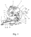
- Fig. 1 shows a combined miter, miter and pull saw.
- a chop saw with traction Prerequisite for the realization of the teaching of the invention, however, is only a chop saw with traction, with saw unit above the workpiece support surface of the carrier or below the workpiece support surface of the carrier. This has already been explained in the general part of the description.
- the chop saw shown initially has a carrier 1, which forms a workpiece support surface 2.
- the rear end of the workpiece support surface 2 here forms a stop rail 3, on which a workpiece, for example a wooden strip, can be applied.
- a holder 4 is mounted, which lies behind the back of the workpiece support surface 2.
- a saw unit 5 Attached to the holder 4 above the carrier 1 is a saw unit 5. In the illustrated and preferred exemplary embodiment, this is pivotable about a transverse axis 6 and is located above the workpiece support surface 2.
- the transverse axis would be omitted.
- the saw unit would be pulled here on tie rods that cantilever over the workpiece support surface.
- the saw unit 5 is about the transverse axis 6 from a raised rest position, the in Fig. 1 can be seen in a lowered sawing, which is not shown here, and pivoted the other way round.
- the saw unit 5 is biased towards the rest position, ie upwards, in particular by a spring. As a result, the saw unit 5, when you let go, returns by itself back to the raised rest position.
- the latter is a special feature of the chop saw, which does not always have to be realized, but is implemented in a particularly appropriate manner here.
- the chop saw shown has a miter function in addition to the previously described Kappfunktion. So it's already a crosscut and miter saw.
- the chop saw on the holder 4 in turn a tilt adjustment 15.
- the saw unit 5 can be compared to the carrier 1 to pivot about a direction of sawing, horizontal tilt pivot axis 16.
- Fig. 2 and 3 let recognize the position of the tilt pivot axis 16 on the holder 4.
- the inclination pivot axis 16 is physically at the specified location.
- a backdrop-like design is possible in which the inclination pivot axis 16 is only geometrically present and the pivoting movement is realized about this virtual pivot axis via other means of construction.
- an angle scale 17 at which one can read off the set angle of inclination. Due to the inclination about the inclination pivot axis 16, the miter angle of the executed saw cut can be adjusted and read off the angle scale 17.
- the illustrated and preferred chop saw has not only a cap function and a miter function, it also has a traction function.
- the saw unit 5 is pivotally mounted on the holder 4 not only by means of the transverse axis 6, but additionally also by means of a Switzerlandfiihrung extending in the sawing direction 18 of two mutually parallel tie rods 18a, b slidably mounted. With this pull function, the saw cut 5 can be extended by the saw unit 5.
- the illustrated and preferred embodiment shows on the support 1 a recessed turntable 19 with a forwardly projecting boom 20 and with a dipping slot 21 into which enters the sawing edge of the saw blade 10.
- the length of the immersion slit 21 is substantially greater than that required for the diameter of the saw blade 10. This is due to the above-described Buchfiihrung 18, which also allows just pulling the saw blade 10 through the workpiece over a certain path.
- Fig. 1 can be seen further that two mutually parallel tie rods 18a, 18b form the Glasfiihrung 18 and are rearwardly connected by a spacer 22 firmly together.
- the tie rods 18a, 18b are fixedly connected to the saw unit 5 and run on the holder 4 in Fig. 2 and 3 recognizable guides 23a, 23b.
- Fig. 2 shows the holder 4 of the preferred embodiment of a chop saw with traction with the two guides 23a, 23b.
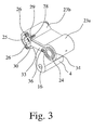
- Fig. 3 shows that in the one guide 23a, a corresponding drawbar 18a, which is not shown here, practically free of play leading slide 24 is inserted in register.
- This sliding guide 24 is a ball bush in the preferred embodiment. But it can also be a different kind of leadership.
- a sliding guide 25 which is used with game.
- Fig. 3 indicates that this slide 25 by means of at least one fixing element 26, in particular a fixing screw, in relation to the guide 23b radially different positions on the holder can be fixed.
- This in Fig. 2 and 3 illustrated embodiment leaves in Fig. 2 above and below the other guide 23b each recognize a threaded bore 27 and points in Fig. 3 , as here above and below the sliding guide 25, the two fixing elements 26 (fixing screws) are positioned.
- the sliding guide 25 in the other guide 23b actually designed as a genuine sliding bush, so not as a ball bushing.
- a ball bush carries much more in the thickness and can not be adjusted as well as a pure sliding bush.
- FIG. 2 and Fig. 3 illustrated embodiment shows yet another peculiarity of this construction, namely that the slide bush in turn fixed by the fixing member 26 position in turn at least partially again with an adjusting element 28, in particular an adjusting screw, is radially readjustable.
- the adjusting element 28 is arranged in a recess 29 of the holder 4.
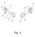
- Fig. 3 indicates that the adjustment screw 28 forming the adjustment screw screwed in an abutment nut inserted laterally in the recess 29 is located. If here the adjusting element 28 forming adjustment screw tightened, so is the in Fig. 4 recognizable divided tab 31 of the slide 25 is pressed inwards and pressed against the running in the guide 23b pull rod 18b. This allows you to adjust the draw resistance of the cable guide 18. In addition, a wear-related adjustment of this slide 25 is guaranteed.
- Fig. 2 and 3 let recognize another particularity of the construction according to the invention, which is characterized in that the sliding guide 24 is formed on the other guide 23b on a pivot lever 33 which is arranged on a flat side of the holder 4 and up to the slide 24 at the one guide 23a extends and is pivotally mounted there.
- This pivot lever 33 thus represents a spacer for the lateral spacing of the two tie rods 18a, 18b.
- the slide guide 25 is part of the pivoting lever 33rd
- the sliding guide 24 on one guide 23a protrudes from the holder 4 to the flat side and forms a pivot axis for a pivot bearing ring 34 of the pivot lever 33.
- the slots 32 are formed for the fixing elements 26 on the pivot lever 33 above and below the sliding guide 25.
- the pivot bearing ring 34 forms with the protruding part of the sliding guide 24 on the one guide 23a, the pivot bearing for the pivot lever 33. Accordingly, the slots 32 have expediently this arc radius corresponding arcuate course.
- Fig. 2 to 4 also belong to the right of the sliding guide 24 is still a threaded bore 35.
- fastener 36 is associated with a substantially circular arc extending slot 37 in the pivot lever 33, which in Fig. 4 recognizes very well.
- the pivot lever 33 is executed in the illustrated and preferred embodiment is particularly flat and wide. That's not exactly how it is done. Namely, it is provided that the pivot lever 33 rests flat on the flat side of the holder 4 and so wide is formed so that it covers all gaps on the guides 23a, 23b and protects against dust entry. Thus, the pivot lever 33, which is arranged yes as the saw unit 11 facing side of the holder 4, additionally fulfills the function of a dust cover or dust seal.
- the pivot lever 33 may suitably consist of a plastic material, in particular a fiber-reinforced plastic material.
- a plastic material comes into question, which also has in the region of the sliding guide 25 particularly good sliding properties. This can be achieved by adding appropriate additives or by coating on the appropriate surfaces.
Landscapes
- Engineering & Computer Science (AREA)
- General Engineering & Computer Science (AREA)
- Mechanical Engineering (AREA)
- Sawing (AREA)
Applications Claiming Priority (1)
| Application Number | Priority Date | Filing Date | Title |
|---|---|---|---|
| DE202008011654U DE202008011654U1 (de) | 2008-09-02 | 2008-09-02 | Kappsäge mit Zugfunktion |
Publications (3)
| Publication Number | Publication Date |
|---|---|
| EP2158991A2 true EP2158991A2 (fr) | 2010-03-03 |
| EP2158991A3 EP2158991A3 (fr) | 2012-07-18 |
| EP2158991B1 EP2158991B1 (fr) | 2018-01-24 |
Family
ID=41361301
Family Applications (1)
| Application Number | Title | Priority Date | Filing Date |
|---|---|---|---|
| EP09010096.7A Not-in-force EP2158991B1 (fr) | 2008-09-02 | 2009-08-05 | Scie circulaire dotée d'une fonction de traction |
Country Status (2)
| Country | Link |
|---|---|
| EP (1) | EP2158991B1 (fr) |
| DE (1) | DE202008011654U1 (fr) |
Families Citing this family (3)
| Publication number | Priority date | Publication date | Assignee | Title |
|---|---|---|---|---|
| DE102010062255A1 (de) | 2010-12-01 | 2012-06-06 | Robert Bosch Gmbh | Kappsäge |
| DE102013224128B3 (de) * | 2013-11-26 | 2015-04-30 | Metabowerke Gmbh | Kapp- und Zugsäge |
| DE102021125710B3 (de) | 2021-10-04 | 2022-11-24 | Metabowerke Gmbh | Kapp- und Zugsäge |
Citations (2)
| Publication number | Priority date | Publication date | Assignee | Title |
|---|---|---|---|---|
| DE20313885U1 (de) | 2002-09-26 | 2003-11-13 | Metabowerke GmbH, 72622 Nürtingen | Kapp- und Gehrungssäge mit Winkeleinstellung an einem Drehteller |
| EP1557231A1 (fr) | 2004-01-22 | 2005-07-27 | Metabowerke GmbH | Scie pivotante avec collecteur de poussière |
Family Cites Families (9)
| Publication number | Priority date | Publication date | Assignee | Title |
|---|---|---|---|---|
| JP3320950B2 (ja) * | 1995-06-15 | 2002-09-03 | 株式会社マキタ | スライドマルノコにおけるスライドバーの支持構造 |
| US5819624A (en) * | 1996-07-30 | 1998-10-13 | Milwaukee Electric Tool Corporation | Indexing override mechanism for a slide compound miter saw |
| JP3549732B2 (ja) * | 1997-07-23 | 2004-08-04 | 株式会社マキタ | スライド機構のストッパ装置 |
| US7207251B2 (en) * | 1999-02-05 | 2007-04-24 | Hitachi Koki Co., Ltd. | Cutter with laser generator that irradiates cutting position on workpiece to facilitate alignment of blade with cutting position |
| US6918330B2 (en) * | 2000-10-24 | 2005-07-19 | Thomson Industries, Inc. | Adjustable tool station |
| US6901834B2 (en) * | 2003-09-26 | 2005-06-07 | Chin-Chin Chang | Movement adjust device for a circular saw |
| JP4534549B2 (ja) * | 2004-03-26 | 2010-09-01 | 日立工機株式会社 | 卓上切断機 |
| JP2005279933A (ja) * | 2004-03-26 | 2005-10-13 | Hitachi Koki Co Ltd | 卓上切断機 |
| TWI288037B (en) * | 2004-07-06 | 2007-10-11 | Hitachi Koki Kk | Miter saw having digital display |
-
2008
- 2008-09-02 DE DE202008011654U patent/DE202008011654U1/de not_active Expired - Lifetime
-
2009
- 2009-08-05 EP EP09010096.7A patent/EP2158991B1/fr not_active Not-in-force
Patent Citations (2)
| Publication number | Priority date | Publication date | Assignee | Title |
|---|---|---|---|---|
| DE20313885U1 (de) | 2002-09-26 | 2003-11-13 | Metabowerke GmbH, 72622 Nürtingen | Kapp- und Gehrungssäge mit Winkeleinstellung an einem Drehteller |
| EP1557231A1 (fr) | 2004-01-22 | 2005-07-27 | Metabowerke GmbH | Scie pivotante avec collecteur de poussière |
Also Published As
| Publication number | Publication date |
|---|---|
| DE202008011654U1 (de) | 2010-01-21 |
| EP2158991B1 (fr) | 2018-01-24 |
| EP2158991A3 (fr) | 2012-07-18 |
Similar Documents
| Publication | Publication Date | Title |
|---|---|---|
| EP1557231B1 (fr) | Scie pivotante avec collecteur de poussière | |
| EP2158991B1 (fr) | Scie circulaire dotée d'une fonction de traction | |
| EP2241396B1 (fr) | Machine-outil, notamment scie à onglet. | |
| DE3718232C2 (fr) | ||
| EP2250005B1 (fr) | Scie circulaire à réglage d'inclinaison | |
| EP1839791B1 (fr) | Scie circulaire à table | |
| DE2133308C3 (de) | Elektrische Handkreissäge | |
| DE3447933A1 (de) | Stichsaege zum bearbeiten von werkstuecken, z.b. aus holz, kunststoffmaterial oder metall | |
| DE202008001743U1 (de) | Kappsäge mit einer Staubabsaugung und/oder einer Verkleidung | |
| EP2250006B1 (fr) | Scie circulaire à réglage d'inclinaison | |
| EP2249989B1 (fr) | Scie circulaire équipée d'une butée de profondeur de coupe | |
| EP2241422B1 (fr) | Scie à onglet dotée d'un réglage de l'inclinaison | |
| DE202006012601U1 (de) | Kapp- und Gehrungssäge mit einem Drehtisch | |
| DE20100087U1 (de) | Handkreissäge | |
| DE202006012418U1 (de) | Kapp- und Gehrungssäge mit einem Drehtisch | |
| EP1518628B1 (fr) | Scie pivotante, en particulier pour le travail du bois | |
| DE19515829C2 (de) | Säge, insbesondere Kreissäge mit einem Tisch | |
| DE2910337C2 (de) | Kombinierte Tisch- und Gehrungssäge | |
| EP2277674B1 (fr) | Machine-outil, en particulier dispositif de sciage | |
| DE202006012341U1 (de) | Kappsäge mit Längssägefunktion | |
| DE7905808U1 (de) | Kombinierte tisch- und kappkreissaege | |
| EP2186588B1 (fr) | Scie circulaire et scie à onglet | |
| EP2216148A1 (fr) | Scie à onglet | |
| DE3206419A1 (de) | Saegeaggregat | |
| EP2231372A1 (fr) | Scie à onglet avec une sécurité pour le transport |
Legal Events
| Date | Code | Title | Description |
|---|---|---|---|
| PUAI | Public reference made under article 153(3) epc to a published international application that has entered the european phase |
Free format text: ORIGINAL CODE: 0009012 |
|
| AK | Designated contracting states |
Kind code of ref document: A2 Designated state(s): AT BE BG CH CY CZ DE DK EE ES FI FR GB GR HR HU IE IS IT LI LT LU LV MC MK MT NL NO PL PT RO SE SI SK SM TR |
|
| AX | Request for extension of the european patent |
Extension state: AL BA RS |
|
| PUAL | Search report despatched |
Free format text: ORIGINAL CODE: 0009013 |
|
| AK | Designated contracting states |
Kind code of ref document: A3 Designated state(s): AT BE BG CH CY CZ DE DK EE ES FI FR GB GR HR HU IE IS IT LI LT LU LV MC MK MT NL NO PL PT RO SE SI SK SM TR |
|
| AX | Request for extension of the european patent |
Extension state: AL BA RS |
|
| RIC1 | Information provided on ipc code assigned before grant |
Ipc: F16C 29/00 20060101ALI20120611BHEP Ipc: B23D 45/04 20060101AFI20120611BHEP Ipc: B23D 47/02 20060101ALI20120611BHEP |
|
| 17P | Request for examination filed |
Effective date: 20120911 |
|
| GRAP | Despatch of communication of intention to grant a patent |
Free format text: ORIGINAL CODE: EPIDOSNIGR1 |
|
| INTG | Intention to grant announced |
Effective date: 20171018 |
|
| GRAS | Grant fee paid |
Free format text: ORIGINAL CODE: EPIDOSNIGR3 |
|
| GRAA | (expected) grant |
Free format text: ORIGINAL CODE: 0009210 |
|
| AK | Designated contracting states |
Kind code of ref document: B1 Designated state(s): AT BE BG CH CY CZ DE DK EE ES FI FR GB GR HR HU IE IS IT LI LT LU LV MC MK MT NL NO PL PT RO SE SI SK SM TR |
|
| REG | Reference to a national code |
Ref country code: GB Ref legal event code: FG4D Free format text: NOT ENGLISH |
|
| REG | Reference to a national code |
Ref country code: CH Ref legal event code: EP |
|
| REG | Reference to a national code |
Ref country code: AT Ref legal event code: REF Ref document number: 965504 Country of ref document: AT Kind code of ref document: T Effective date: 20180215 |
|
| REG | Reference to a national code |
Ref country code: IE Ref legal event code: FG4D Free format text: LANGUAGE OF EP DOCUMENT: GERMAN |
|
| REG | Reference to a national code |
Ref country code: DE Ref legal event code: R096 Ref document number: 502009014694 Country of ref document: DE |
|
| REG | Reference to a national code |
Ref country code: NL Ref legal event code: MP Effective date: 20180124 |
|
| REG | Reference to a national code |
Ref country code: LT Ref legal event code: MG4D |
|
| PG25 | Lapsed in a contracting state [announced via postgrant information from national office to epo] |
Ref country code: NL Free format text: LAPSE BECAUSE OF FAILURE TO SUBMIT A TRANSLATION OF THE DESCRIPTION OR TO PAY THE FEE WITHIN THE PRESCRIBED TIME-LIMIT Effective date: 20180124 |
|
| PG25 | Lapsed in a contracting state [announced via postgrant information from national office to epo] |
Ref country code: HR Free format text: LAPSE BECAUSE OF FAILURE TO SUBMIT A TRANSLATION OF THE DESCRIPTION OR TO PAY THE FEE WITHIN THE PRESCRIBED TIME-LIMIT Effective date: 20180124 Ref country code: CY Free format text: LAPSE BECAUSE OF FAILURE TO SUBMIT A TRANSLATION OF THE DESCRIPTION OR TO PAY THE FEE WITHIN THE PRESCRIBED TIME-LIMIT Effective date: 20180124 Ref country code: FI Free format text: LAPSE BECAUSE OF FAILURE TO SUBMIT A TRANSLATION OF THE DESCRIPTION OR TO PAY THE FEE WITHIN THE PRESCRIBED TIME-LIMIT Effective date: 20180124 Ref country code: NO Free format text: LAPSE BECAUSE OF FAILURE TO SUBMIT A TRANSLATION OF THE DESCRIPTION OR TO PAY THE FEE WITHIN THE PRESCRIBED TIME-LIMIT Effective date: 20180424 Ref country code: ES Free format text: LAPSE BECAUSE OF FAILURE TO SUBMIT A TRANSLATION OF THE DESCRIPTION OR TO PAY THE FEE WITHIN THE PRESCRIBED TIME-LIMIT Effective date: 20180124 Ref country code: LT Free format text: LAPSE BECAUSE OF FAILURE TO SUBMIT A TRANSLATION OF THE DESCRIPTION OR TO PAY THE FEE WITHIN THE PRESCRIBED TIME-LIMIT Effective date: 20180124 |
|
| REG | Reference to a national code |
Ref country code: FR Ref legal event code: PLFP Year of fee payment: 10 |
|
| PG25 | Lapsed in a contracting state [announced via postgrant information from national office to epo] |
Ref country code: LV Free format text: LAPSE BECAUSE OF FAILURE TO SUBMIT A TRANSLATION OF THE DESCRIPTION OR TO PAY THE FEE WITHIN THE PRESCRIBED TIME-LIMIT Effective date: 20180124 Ref country code: SE Free format text: LAPSE BECAUSE OF FAILURE TO SUBMIT A TRANSLATION OF THE DESCRIPTION OR TO PAY THE FEE WITHIN THE PRESCRIBED TIME-LIMIT Effective date: 20180124 Ref country code: BG Free format text: LAPSE BECAUSE OF FAILURE TO SUBMIT A TRANSLATION OF THE DESCRIPTION OR TO PAY THE FEE WITHIN THE PRESCRIBED TIME-LIMIT Effective date: 20180424 Ref country code: GR Free format text: LAPSE BECAUSE OF FAILURE TO SUBMIT A TRANSLATION OF THE DESCRIPTION OR TO PAY THE FEE WITHIN THE PRESCRIBED TIME-LIMIT Effective date: 20180425 Ref country code: IS Free format text: LAPSE BECAUSE OF FAILURE TO SUBMIT A TRANSLATION OF THE DESCRIPTION OR TO PAY THE FEE WITHIN THE PRESCRIBED TIME-LIMIT Effective date: 20180524 Ref country code: PL Free format text: LAPSE BECAUSE OF FAILURE TO SUBMIT A TRANSLATION OF THE DESCRIPTION OR TO PAY THE FEE WITHIN THE PRESCRIBED TIME-LIMIT Effective date: 20180124 |
|
| PG25 | Lapsed in a contracting state [announced via postgrant information from national office to epo] |
Ref country code: MT Free format text: LAPSE BECAUSE OF FAILURE TO SUBMIT A TRANSLATION OF THE DESCRIPTION OR TO PAY THE FEE WITHIN THE PRESCRIBED TIME-LIMIT Effective date: 20180124 |
|
| REG | Reference to a national code |
Ref country code: DE Ref legal event code: R097 Ref document number: 502009014694 Country of ref document: DE |
|
| PG25 | Lapsed in a contracting state [announced via postgrant information from national office to epo] |
Ref country code: IT Free format text: LAPSE BECAUSE OF FAILURE TO SUBMIT A TRANSLATION OF THE DESCRIPTION OR TO PAY THE FEE WITHIN THE PRESCRIBED TIME-LIMIT Effective date: 20180124 Ref country code: RO Free format text: LAPSE BECAUSE OF FAILURE TO SUBMIT A TRANSLATION OF THE DESCRIPTION OR TO PAY THE FEE WITHIN THE PRESCRIBED TIME-LIMIT Effective date: 20180124 Ref country code: EE Free format text: LAPSE BECAUSE OF FAILURE TO SUBMIT A TRANSLATION OF THE DESCRIPTION OR TO PAY THE FEE WITHIN THE PRESCRIBED TIME-LIMIT Effective date: 20180124 |
|
| PG25 | Lapsed in a contracting state [announced via postgrant information from national office to epo] |
Ref country code: SM Free format text: LAPSE BECAUSE OF FAILURE TO SUBMIT A TRANSLATION OF THE DESCRIPTION OR TO PAY THE FEE WITHIN THE PRESCRIBED TIME-LIMIT Effective date: 20180124 Ref country code: DK Free format text: LAPSE BECAUSE OF FAILURE TO SUBMIT A TRANSLATION OF THE DESCRIPTION OR TO PAY THE FEE WITHIN THE PRESCRIBED TIME-LIMIT Effective date: 20180124 Ref country code: SK Free format text: LAPSE BECAUSE OF FAILURE TO SUBMIT A TRANSLATION OF THE DESCRIPTION OR TO PAY THE FEE WITHIN THE PRESCRIBED TIME-LIMIT Effective date: 20180124 Ref country code: CZ Free format text: LAPSE BECAUSE OF FAILURE TO SUBMIT A TRANSLATION OF THE DESCRIPTION OR TO PAY THE FEE WITHIN THE PRESCRIBED TIME-LIMIT Effective date: 20180124 |
|
| PLBE | No opposition filed within time limit |
Free format text: ORIGINAL CODE: 0009261 |
|
| STAA | Information on the status of an ep patent application or granted ep patent |
Free format text: STATUS: NO OPPOSITION FILED WITHIN TIME LIMIT |
|
| 26N | No opposition filed |
Effective date: 20181025 |
|
| PG25 | Lapsed in a contracting state [announced via postgrant information from national office to epo] |
Ref country code: SI Free format text: LAPSE BECAUSE OF FAILURE TO SUBMIT A TRANSLATION OF THE DESCRIPTION OR TO PAY THE FEE WITHIN THE PRESCRIBED TIME-LIMIT Effective date: 20180124 |
|
| PG25 | Lapsed in a contracting state [announced via postgrant information from national office to epo] |
Ref country code: MC Free format text: LAPSE BECAUSE OF FAILURE TO SUBMIT A TRANSLATION OF THE DESCRIPTION OR TO PAY THE FEE WITHIN THE PRESCRIBED TIME-LIMIT Effective date: 20180124 |
|
| REG | Reference to a national code |
Ref country code: CH Ref legal event code: PL |
|
| PG25 | Lapsed in a contracting state [announced via postgrant information from national office to epo] |
Ref country code: LU Free format text: LAPSE BECAUSE OF NON-PAYMENT OF DUE FEES Effective date: 20180805 Ref country code: LI Free format text: LAPSE BECAUSE OF NON-PAYMENT OF DUE FEES Effective date: 20180831 Ref country code: CH Free format text: LAPSE BECAUSE OF NON-PAYMENT OF DUE FEES Effective date: 20180831 |
|
| REG | Reference to a national code |
Ref country code: BE Ref legal event code: MM Effective date: 20180831 |
|
| REG | Reference to a national code |
Ref country code: IE Ref legal event code: MM4A |
|
| PG25 | Lapsed in a contracting state [announced via postgrant information from national office to epo] |
Ref country code: IE Free format text: LAPSE BECAUSE OF NON-PAYMENT OF DUE FEES Effective date: 20180805 |
|
| PG25 | Lapsed in a contracting state [announced via postgrant information from national office to epo] |
Ref country code: BE Free format text: LAPSE BECAUSE OF NON-PAYMENT OF DUE FEES Effective date: 20180831 |
|
| REG | Reference to a national code |
Ref country code: AT Ref legal event code: MM01 Ref document number: 965504 Country of ref document: AT Kind code of ref document: T Effective date: 20180805 |
|
| PG25 | Lapsed in a contracting state [announced via postgrant information from national office to epo] |
Ref country code: AT Free format text: LAPSE BECAUSE OF NON-PAYMENT OF DUE FEES Effective date: 20180805 |
|
| PG25 | Lapsed in a contracting state [announced via postgrant information from national office to epo] |
Ref country code: TR Free format text: LAPSE BECAUSE OF FAILURE TO SUBMIT A TRANSLATION OF THE DESCRIPTION OR TO PAY THE FEE WITHIN THE PRESCRIBED TIME-LIMIT Effective date: 20180124 |
|
| PG25 | Lapsed in a contracting state [announced via postgrant information from national office to epo] |
Ref country code: HU Free format text: LAPSE BECAUSE OF FAILURE TO SUBMIT A TRANSLATION OF THE DESCRIPTION OR TO PAY THE FEE WITHIN THE PRESCRIBED TIME-LIMIT; INVALID AB INITIO Effective date: 20090805 Ref country code: PT Free format text: LAPSE BECAUSE OF FAILURE TO SUBMIT A TRANSLATION OF THE DESCRIPTION OR TO PAY THE FEE WITHIN THE PRESCRIBED TIME-LIMIT Effective date: 20180124 |
|
| PG25 | Lapsed in a contracting state [announced via postgrant information from national office to epo] |
Ref country code: MK Free format text: LAPSE BECAUSE OF NON-PAYMENT OF DUE FEES Effective date: 20180124 |
|
| PGFP | Annual fee paid to national office [announced via postgrant information from national office to epo] |
Ref country code: FR Payment date: 20200820 Year of fee payment: 12 Ref country code: GB Payment date: 20200825 Year of fee payment: 12 |
|
| GBPC | Gb: european patent ceased through non-payment of renewal fee |
Effective date: 20210805 |
|
| PG25 | Lapsed in a contracting state [announced via postgrant information from national office to epo] |
Ref country code: GB Free format text: LAPSE BECAUSE OF NON-PAYMENT OF DUE FEES Effective date: 20210805 Ref country code: FR Free format text: LAPSE BECAUSE OF NON-PAYMENT OF DUE FEES Effective date: 20210831 |
|
| PGFP | Annual fee paid to national office [announced via postgrant information from national office to epo] |
Ref country code: DE Payment date: 20240819 Year of fee payment: 16 |
|
| REG | Reference to a national code |
Ref country code: DE Ref legal event code: R119 Ref document number: 502009014694 Country of ref document: DE |