EP2159128A2 - Mehrsystemkonfiguration zur Zugsicherung - Google Patents
Mehrsystemkonfiguration zur Zugsicherung Download PDFInfo
- Publication number
- EP2159128A2 EP2159128A2 EP09167589A EP09167589A EP2159128A2 EP 2159128 A2 EP2159128 A2 EP 2159128A2 EP 09167589 A EP09167589 A EP 09167589A EP 09167589 A EP09167589 A EP 09167589A EP 2159128 A2 EP2159128 A2 EP 2159128A2
- Authority
- EP
- European Patent Office
- Prior art keywords
- coupling
- master
- input module
- system configuration
- etcs
- Prior art date
- Legal status (The legal status is an assumption and is not a legal conclusion. Google has not performed a legal analysis and makes no representation as to the accuracy of the status listed.)
- Granted
Links
- 230000008878 coupling Effects 0.000 claims abstract description 16
- 238000010168 coupling process Methods 0.000 claims abstract description 16
- 238000005859 coupling reaction Methods 0.000 claims abstract description 16
- 230000003213 activating effect Effects 0.000 claims abstract description 6
- 230000004913 activation Effects 0.000 description 3
- 230000009849 deactivation Effects 0.000 description 3
- 230000002093 peripheral effect Effects 0.000 description 3
- 230000003993 interaction Effects 0.000 description 2
- 230000000712 assembly Effects 0.000 description 1
- 238000000429 assembly Methods 0.000 description 1
- 230000008901 benefit Effects 0.000 description 1
- 230000005540 biological transmission Effects 0.000 description 1
- 230000001939 inductive effect Effects 0.000 description 1
- 238000005259 measurement Methods 0.000 description 1
- 238000002161 passivation Methods 0.000 description 1
- 239000000725 suspension Substances 0.000 description 1
Images
Classifications
-
- B—PERFORMING OPERATIONS; TRANSPORTING
- B61—RAILWAYS
- B61L—GUIDING RAILWAY TRAFFIC; ENSURING THE SAFETY OF RAILWAY TRAFFIC
- B61L15/00—Indicators provided on the vehicle or train for signalling purposes
- B61L15/0063—Multiple on-board control systems, e.g. "2 out of 3"-systems
-
- B—PERFORMING OPERATIONS; TRANSPORTING
- B61—RAILWAYS
- B61L—GUIDING RAILWAY TRAFFIC; ENSURING THE SAFETY OF RAILWAY TRAFFIC
- B61L25/00—Recording or indicating positions or identities of vehicles or trains or setting of track apparatus
- B61L25/02—Indicating or recording positions or identities of vehicles or trains
- B61L25/026—Relative localisation, e.g. using odometer
-
- B—PERFORMING OPERATIONS; TRANSPORTING
- B61—RAILWAYS
- B61L—GUIDING RAILWAY TRAFFIC; ENSURING THE SAFETY OF RAILWAY TRAFFIC
- B61L27/00—Central railway traffic control systems; Trackside control; Communication systems specially adapted therefor
- B61L27/20—Trackside control of safe travel of vehicle or train, e.g. braking curve calculation
- B61L2027/202—Trackside control of safe travel of vehicle or train, e.g. braking curve calculation using European Train Control System [ETCS]
Definitions
- the invention relates to a multi-system configuration for train protection with a train-side legacy system, which has a position encoder for speed determination, and a master system, in particular ETCS (European Train Control System).
- ETCS European Train Control System
- the ETCS is intended to replace the large number of train protection systems deployed in European countries, thereby enabling dense, fast and cross-border train control throughout Europe. To ensure safe and smooth train service, train protection systems are necessary. In Europe, more than 10 species have evolved, some of which are side-by-side and country-specific and are incompatible with each other.
- STMs Specific Transmissions Modules
- the EP 1 681 222 A1 proposed the interposition of an STM gateway to adapt the different interfaces of the legacy systems to an STM interface of the ETCS.
- the invention has for its object to provide a multi-system configuration of the generic type, in a simple way, an upgrade of the legacy system is possible, with only peripheral adjustments to the legacy system should be required.
- the object is achieved in that the master system is connected to the Wegimpulsgeber via a coupling and a controller board, wherein the master system generates control signals for activating or deactivating the Wegimpusgebers and a cab signal.
- the master system By connecting the master system to the position encoder instead of a gateway connection, the effort to replace certain functionalities of the legacy system by higher-level functionalities of the master system can be significantly reduced.
- the master system generates control signals for activating the position encoder and the cab signal, whereby a first mode "stand-alone system” is selected or control signals to deactivate the Wegimpulsgebers and the cab signal, by which the distance encoder of the old system is deactivated, so that a second mode "mixing system "is selected. Only the interplay between position encoder and cab signal leads to the activation or deactivation of components of the legacy system.
- the coupling acts on both the start-up module of the position encoder and an input module for activating / deactivating the guidance signal.
- the master system generates control signals for activating or deactivating the train control and the Wegimpulsgebers the old system.
- information generated on the trackside and / or sensors for the speed determination are replaced by own functionalities of the master system.
- the train control is replaced in ETCS as a master system, for example by Balisenempfang or more comfortable radio reception.
- the legacy system for example, a Doppler radar sensor of the ETCS occur.
- the status of the coupling is detected according to claim 3 using a current coupler and reported to the input module.
- the legacy system When the master system is in operation, the legacy system according to claim 5 reports back to the master system via the interface module of the position encoder and the coupling. In addition already existing function control signals of the old system are used.
- a peripheral wiring of the old system by the controller board and the input module is sufficient. Internal changes to the legacy system itself are not required, so that in the inventive upgrade to a multi-system configuration no new and usually very expensive safety-related evidence for the purpose of release by the respective approval authority are required.
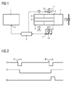
- FIG. 1 shows an ETCS - European Train Control System - 1 as a master system in cooperation with a legacy system 2 for train protection.
- the old system 2 is equipped with the usual modules input 3, display 4, 5 antenna assembly and Wegimpulsgeber 6, which act on a brake intervention 7 for safety-related emergency braking.
- the legacy system 2 is usually connected to at least one input module 8.
- the ETCS 1 is connected via a coupling 9 and a controller board 11 with the Wegimpulsgeber 6 of the legacy system 2.
- the ETCS 1 sends via the coupling 9, which is used for signal matching and signal selection, control signals 11 to the controller board 10, whereby the functionality of the position encoder 6 is either activated or deactivated. This switching or first switching takes place together with the control of the input module 8, whereby a cab suspension or locking is effected.
- the energization of the input module 8 via a current coupler 12, which is controlled by the coupling 9 when the coupling 9 has the control signal 11 to the controller board 10 of the position encoder 6 through-connected. When activated, the remain entire functions of the legacy system 2 unchanged, so that the legacy system 2 operates in stand-alone mode.
- Deactivation of the Wegimpulsgebers 6 and the Fhackstandsignals leads to the replacement of the functionality of the Wegimpulsgebers 6 and switched from the cab signal antenna assembly 5 by ETCS own functions, especially based on a Doppler radar sensor and a Balisen- or Funkzugbeein kgung.
- ETCS own functions especially based on a Doppler radar sensor and a Balisen- or Funkzugbeein kgung.
- the legacy system 2 continuously transmits status signals 13 via the controller board 10 or the input module 8 and the coupling 9 back to the master system ETCS 1, so that ultimately the ETCS 1 takes over the control and the functional control of the legacy system 2.
- the ETCS 1 can block or enable a reset switch 14 to maintain special properties of the legacy system 2.
- the ETCS 1 can forward further safety functions, which the legacy system 2 does not offer, via the coupling 9 and the interface module 10 or the input module 8 to the brake intervention 7 of the old system 2.
- FIG. 2 shows passages with respect to position encoder 6, input module 8, ie driver's signal, and residual switch 14.
- the cab signal can be locked via the input module 8.
- the antenna assembly 5 is turned off. Thereafter, the Wegimpulsgeber 6 can be active again - with sealed cab signal.
- the legacy system switches to stand-alone mode. Of the Reset switch 14 is enabled and can be operated if necessary, as the lower waveform shows.
Landscapes
- Engineering & Computer Science (AREA)
- Mechanical Engineering (AREA)
- Electric Propulsion And Braking For Vehicles (AREA)
- Train Traffic Observation, Control, And Security (AREA)
Abstract
Description
- Die Erfindung betrifft eine Mehrsystemkonfiguration zur Zugsicherung mit einem zugseitigen Altsystem, welches einen Wegimpulsgeber zur Geschwindigkeitsermittlung aufweist, und einem Mastersystem, insbesondere ETCS (European Train Control System).
- Das ETCS soll die Vielzahl der in den europäischen Ländern eingesetzten Zugsicherungssysteme ablösen und so eine dichte, schnelle und grenzüberschreitende Zugführung in ganz Europa ermöglichen. Um einen sicheren und reibungslosen Zugverkehr zu gewährleisten, sind Zugsicherungssysteme notwendig. In Europa haben sich mehr als 10 Arten entwickelt, die teilweise nebeneinander und länderabhängig eingesetzt werden und untereinander nicht kompatibel sind.
- Zur Anpassung der nicht ETCS-kompatiblen nationalen Zugsicherungssteme an das ETCS-Fahrzeuggerät werden üblicherweise STMs (Specific Transmmission Moduls) eingesetzt. Diese ermöglichen die Weiterbenutzung der nationalen Zugsicherungssysteme, beispielsweise INDUSI, LZB, ZUB, SIGNUM, TVM, in einer Übergangsphase. Die STM-Module übersetzen Informationen von diesen alten Zugsicherungssystemen, so dass ein mit einem ETCS-Fahrzeuggerät und einem STM-Modul ausgestattetes Triebfahrzeug diese Strecken mit der entsprechenden länderspezifischen Funktionalität befahren kann.
- Die Entwicklung der verschiedenen STMs muss den Anforderungen der Norm CENELEC 50126 genügen, welche die Anforderungen an Zuverlässigkeit, Verfügbarkeit, Instandhaltbarkeit und Sicherheit sowie deren Wechselwirkungen definiert. Da diese Norm bei Änderungen bzw. Neuentwicklung auch für die z. T. sehr alten nationalen Zugsicherungssysteme berücksichtigt werden muss, ist der Entwicklungsaufwand für die STMs sehr hoch.
- Um den Aufwand zur Anbindung des Altsystems an das ETCS zu reduzieren, wurde gemäß der
EP 1 681 222 A1 die Zwischenschaltung eines STM-Gateways zur Anpassung der unterschiedlichen Schnittstellen der Altsysteme an eine STM-Schnittstelle des ETCS vorgeschlagen. - Der Erfindung liegt die Aufgabe zugrunde, eine Mehrsystemkonfiguration der gattungsgemäßen Art anzugeben, bei der auf einfache Weise eine Hochrüstung des Altsystems möglich ist, wobei nur periphere Anpassungen am Altsystem erforderlich sein sollen.
- Erfindungsgemäß wird die Aufgabe dadurch gelöst, dass das Mastersystem mit dem Wegimpulsgeber über eine Kopplung und eine Anschaltbaugruppe verbunden ist, wobei das Mastersystem Steuersignale zur Aktivierung oder Deaktivierung des Wegimpusgebers und eines Führerstandssignals erzeugt.
- Durch die Anbindung des Mastersystems an den Wegimpulsgeber anstelle einer Gateway-Verbindung kann der Aufwand zum Ersatz bestimmter Funktionalitäten des Altsystems durch höherwertige Funktionalitäten des Mastersystems erheblich reduziert werden. Das Mastersystem generiert Steuersignale zur Aktivierung des Wegimpulsgebers und des Führerstandssignals, wodurch eine erste Betriebsart "Stand-alone Altsystem" angewählt ist oder Steuersignale zur Deaktivierung des Wegimpulsgebers und des Führerstandssignals, durch die der Wegimpulsgeber des Altsystems deaktiviert wird, so dass eine zweite Betriebsart "Mischsystem" angewählt ist. Erst das Zusammenspiel zwischen Wegimpulsgeber und Führerstandssignal führt zur Aktivierung oder Deaktivierung von Komponenten des Altsystems. Durch Abriegelung des Führerstandssignals werden Antennenbaugruppen zum Empfang streckenseitig erzeugter Informationen, beispielsweise INDUSI(induktive Zugsicherung)-Magnete passiviert und durch Aufriegelung des Führstandsignals aktiviert. Dadurch ergibt sich der Vorteil, dass Geschwindigkeitsmessung und streckenseitige Zugbeeinflussung des Altsystems bedarfsgerecht aktiviert und deaktiviert werden können. In der ersten Betriebsart "Stand-alone Altsystem" bleiben Funktion, Anzeige, Bedienung und Fehleroffenbarung des Altsystems komplett erhalten. Die Kopplung wird dabei als rückwirkungsfrei vorausgesetzt. In der zweiten Betriebsart "Mischsystem" werden Komponenten des Altsystems deaktiviert, wodurch das Mastersystem diese Funktionalitäten übernehmen kann. Die restlichen Komponenten des Altsystems, die anderen Funktionalitäten zugeordnet sind, bleiben davon unberührt und sind weiterhin in Betrieb. Auf diese Weise ergibt sich eine kostengünstige Hochrüstung der Altsysteme von Stand-alone-Betrieb zu Mischbetrieb, wobei am Altsystem nur periphere Ein-Aus-Baugruppen zur Aktivierung bzw. Deaktivierung erforderlich sind.
- Gemäß Anspruch 2 beaufschlagt die Kopplung sowohl die Anschaltbaugruppe des Wegimpulsgebers als auch eine Eingabebaugruppe zur Aktivierung/Deaktivierung des Führstandsignals. Somit erzeugt das Mastersystem Steuersignale zur Aktivierung oder Deaktivierung der Zugbeeinflussung und des Wegimpulsgebers des Altsystems. Dadurch werden streckenseitig erzeugte Informationen und/oder Sensoren für die Geschwindigkeitsermittlung durch eigene Funktionalitäten des Mastersystems ersetzt. Die Zugbeeinflussung wird bei ETCS als Mastersystem beispielsweise durch Balisenempfang oder komfortableren Funkempfang ersetzt. Anstelle des herkömmlichen Wegimpulsgebers des Altsystems kann beispielsweise eine Dopplerradarsensorik des ETCS treten.
- Der Status der Kopplung wird gemäß Anspruch 3 mit Hilfe eines Stromkopplers erfasst und an die Eingabebaugruppe gemeldet.
- Wenn das Mastersystem in Betrieb ist, meldet das Altsystem gemäß Anspruch 5 über die Anschaltbaugruppe des Wegimpulsgebers und die Kopplung seinen Status an das Mastersystem zurück. Dazu werden ohnehin vorhandene Funktionskontrollsignale des Altsystems genutzt.
- Eine periphere Beschaltung des Altsystems durch die Anschaltbaugruppe und die Eingabebaugruppe genügt. Interne Änderungen am Altsystem selbst sind nicht erforderlich, so dass bei der erfindungsgemäßen Hochrüstung zu einer Mehrsystemkonfiguration keine neuen und üblicherweise sehr aufwendigen sicherheitstechnischen Nachweise zum Zwecke der Freigabe durch die jeweilige Zulassungsbehörde erforderlich sind.
- Die Erfindung wird nachfolgend anhand figürlicher Darstellungen näher erläutert. Es zeigen:
- Figur 1
- eine Ausführungsform einer Mehrsystemkonfiguration und
- Figur 2
- Signalverläufe.
-
Figur 1 zeigt ein ETCS - European Train Control System - 1 als Mastersystem im Zusammenwirken mit einem Altsystem 2 zur Zugsicherung. Das Altsystem 2 ist mit den üblichen Baugruppen Eingabe 3, Anzeige 4, Antennenbaugruppe 5 und Wegimpulsgeber 6 ausgestattet, die einen Bremseingriff 7 zur sicherheitsrelevanten Zwangsbremsung beaufschlagen. Peripher ist das Altsystem 2 üblicherweise mindestens mit einer Eingabebaugruppe 8 beschaltet. - Das ETCS 1 ist über eine Kopplung 9 und eine Anschaltbaugruppe 11 mit dem Wegimpulsgeber 6 des Altsystems 2 verbunden. Das ETCS 1 sendet über die Kopplung 9, die zur Signalanpassung und Signalauswahl dient, Steuersignale 11 an die Anschaltbaugruppe 10, wodurch die Funktionalität des Wegimpulsgebers 6 entweder aktiviert oder deaktiviert wird. Diese Umschaltung oder Ersteinschaltung erfolgt zusammen mit der Ansteuerung der Eingabebaugruppe 8, wodurch eine Führerstandsaufriegelung oder Abriegelung bewirkt wird. Die Bestromung der Eingabebaugruppe 8 erfolgt über einen Stromkoppler 12, der von der Kopplung 9 gesteuert wird, wenn die Kopplung 9 das Steuersignal 11 zu der Anschaltbaugruppe 10 des Wegimpulsgebers 6 durchgeschaltet hat. Bei Aktivierung bleiben die gesamten Funktionen des Altsystems 2 unverändert, so dass das Altsystem 2 im Stand-alone-Modus arbeitet. Deaktiiverung des Wegimpulsgebers 6 und des Führstandsignals führt zum Ersatz der Funktionalität des Wegimpulsgebers 6 und der vom Führerstandsignal geschalteten Antennenbaugruppe 5 durch ETCSeigene Funktionen, insbesondere auf der Basis einer Dopplerradarsensorik und einer Balisen- oder Funkzugbeeinflussung. Auf diese Weise werden nur die Baugruppen Wegimpulsgeber 6 und Antennenbaugruppe 5 des Altsystems 2 quasi umgangen. Die anderen Funktionalitäten, insbesondere die des Bremseingriffes 7 des Altsystems 2, sind weiterhin aktiv. Das Altsystem 2 übermittelt laufend Statussignale 13 über die Anschaltbaugruppe 10 bzw. die Eingabebaugruppe 8 und die Kopplung 9 zurück an das Mastersystem ETCS 1, so dass letztlich das ETCS 1 die Steuerung und die Funktionskontrolle des Altsystems 2 übernimmt. Das ETCS 1 kann dabei einen Resetschalter 14 zur Erhaltung besonderer Eigenschaften des Altsystems 2 blockieren oder freischalten.
- Zusätzlich kann das ETCS 1 weitere Sicherheitsfunktionen, die das Altsystem 2 nicht bietet, über die Kopplung 9 und die Anschaltbaugruppe 10 oder die Eingabebaugruppe 8 an den Bremseingriff 7 des Altsystems 2 weiterleiten.
-
Figur 2 zeigt Signalverläufe bezüglich Wegimpulsgeber 6, Eingabebaugruppe 8, d. h. Führerstandssignal, und Restschalter 14. Zur Passivierung A wird am Wegimpulsgeber 6 durch das ETCS 1 kurzzeitig ein Geschwindigkeitswert v = 0 erzeugt - auch während der Fahrt. Dadurch lässt sich das Führerstandssignal über die Eingabebaugruppe 8 abriegeln. Die Antennenbaugruppe 5 wird abgeschaltet. Danach kann der Wegimpulsgeber 6 wieder aktiv sein - bei abgeriegeltem Führerstandsignal. - Zur Aktivierung B wird wiederum durch das ETCS 1 zunächst der Wegimpulsgeber 6 angesteuert, um den Geschwindigkeitswert v = 0 zu erzeugen. Dadurch lässt sich das Führerstandssignal aufriegeln. Das Altsystem wechselt in den Stand-alone-Modus. Der Resetschalter 14 wird freigeschaltet und kann ggf. betätigt werden, wie der untere Signalverlauf zeigt.
Claims (5)
- Mehrsystemkonfiguration zur Zugsicherung mit einem zugseitigen Altsystem (2), welches einen Wegimpulsgeber (6) zur Geschwindigkeitsermittlung aufweist, und einem Mastersystem, insbesondere ETCS - European Train Control System - (1),
dadurch gekennzeichnet, dass
das Mastersystem mit dem Wegimpulsgeber (6) über eine Kopplung (9) und eine Anschaltbaugruppe (10) verbunden ist, wobei das Mastersystem Steuersignale (11) zur Aktivierung oder Deaktivierung des Wegimpulsgebers (6) und eines Führerstandsignals erzeugt. - Mehrsystemkonfiguration nach Anspruch 1,
dadurch gekennzeichnet, dass
die Kopplung (9) sowohl die Anschaltbaugruppe (10) als auch eine Eingabebaugruppe (8) des Altsystems beaufschlagt. - Mehrsystemkonfiguration Anspruch 2,
dadurch gekennzeichnet, dass
die Kopplung (9) über einen Stromkoppler (12) mit der Eingabebaugruppe (8) verbunden ist. - Mehrsystemkonfiguration nach Anspruch 2 oder 3,
dadurch gekennzeichnet, dass
die Eingabebaugruppe (8) einen Resetschalter (14) aufweist. - Mehrsystemkonfiguration nach einem der vorangehenden Ansprüche,
dadurch gekennzeichnet, dass
das Altsystem (2) Statussignale (13) über die Anschaltbaugruppe (10) bzw. die Eingabebaugruppe (8) und die Kopplung (9) an das Mastersystem überträgt.
Applications Claiming Priority (1)
| Application Number | Priority Date | Filing Date | Title |
|---|---|---|---|
| DE102008045051A DE102008045051A1 (de) | 2008-08-27 | 2008-08-27 | Mehrsystemkonfiguration zur Zugsicherung |
Publications (3)
| Publication Number | Publication Date |
|---|---|
| EP2159128A2 true EP2159128A2 (de) | 2010-03-03 |
| EP2159128A3 EP2159128A3 (de) | 2010-10-06 |
| EP2159128B1 EP2159128B1 (de) | 2011-07-20 |
Family
ID=41278893
Family Applications (1)
| Application Number | Title | Priority Date | Filing Date |
|---|---|---|---|
| EP09167589A Not-in-force EP2159128B1 (de) | 2008-08-27 | 2009-08-11 | Mehrsystemkonfiguration zur Zugsicherung |
Country Status (5)
| Country | Link |
|---|---|
| EP (1) | EP2159128B1 (de) |
| AT (1) | ATE517011T1 (de) |
| DE (1) | DE102008045051A1 (de) |
| DK (1) | DK2159128T3 (de) |
| ES (1) | ES2366392T3 (de) |
Families Citing this family (3)
| Publication number | Priority date | Publication date | Assignee | Title |
|---|---|---|---|---|
| DE102013203124A1 (de) * | 2013-02-26 | 2014-08-28 | Siemens Aktiengesellschaft | Schienenfahrzeug mit einer Tachometer-Geschwindigkeitsanzeigeeinrichtung und Verfahren zum Betreiben eines solchen Schienenfahrzeugs |
| CN110712667B (zh) * | 2018-07-12 | 2022-07-01 | 北京全路通信信号研究设计院集团有限公司 | 一种能够适应国外要求的综合列控系统 |
| DE102021209365A1 (de) | 2021-08-26 | 2023-03-02 | Knick Elektronische Messgeräte GmbH & Co. KG | Impulssignalvervielfacher zur Bereitstellung eines sekundären Impulssignals aus einem primären Impulssignal eines Impulssignalgebers |
Citations (1)
| Publication number | Priority date | Publication date | Assignee | Title |
|---|---|---|---|---|
| EP1681222A1 (de) | 2005-01-17 | 2006-07-19 | Siemens Aktiengesellschaft | Zugbeeinflussungssystem |
Family Cites Families (1)
| Publication number | Priority date | Publication date | Assignee | Title |
|---|---|---|---|---|
| DE102006033614B4 (de) * | 2006-07-18 | 2012-08-30 | Deutsches Zentrum für Luft- und Raumfahrt e.V. | Vorrichtung zur Zugsicherung |
-
2008
- 2008-08-27 DE DE102008045051A patent/DE102008045051A1/de not_active Withdrawn
-
2009
- 2009-08-11 ES ES09167589T patent/ES2366392T3/es active Active
- 2009-08-11 DK DK09167589.2T patent/DK2159128T3/da active
- 2009-08-11 EP EP09167589A patent/EP2159128B1/de not_active Not-in-force
- 2009-08-11 AT AT09167589T patent/ATE517011T1/de active
Patent Citations (1)
| Publication number | Priority date | Publication date | Assignee | Title |
|---|---|---|---|---|
| EP1681222A1 (de) | 2005-01-17 | 2006-07-19 | Siemens Aktiengesellschaft | Zugbeeinflussungssystem |
Also Published As
| Publication number | Publication date |
|---|---|
| DK2159128T3 (da) | 2011-10-24 |
| EP2159128A3 (de) | 2010-10-06 |
| EP2159128B1 (de) | 2011-07-20 |
| ATE517011T1 (de) | 2011-08-15 |
| DE102008045051A1 (de) | 2010-03-04 |
| ES2366392T3 (es) | 2011-10-19 |
Similar Documents
| Publication | Publication Date | Title |
|---|---|---|
| EP3600994B1 (de) | Elektronisch steuerbares bremssystem sowie verfahren zum steuern des elektronisch steuerbaren bremssystems mit rein elektrischem bremswertgeber | |
| EP2176106B1 (de) | Bremssystem für ein fahrzeug und verfahren zum betreiben eines bremssystems für ein fahrzeug | |
| EP3405377B1 (de) | Ato-einrichtung, schienenfahrzeug und verfahren zum automatisierten fahren eines schienenfahrzeugs | |
| EP3612430B1 (de) | Verfahren zum betreiben eines spurgebundenen verkehrssystems und vorrichtung | |
| EP2443016B1 (de) | Verfahren zur zugdateneingabe bei einer mehrsystemkonfiguration zur zugsicherung und mehrsystemkonfiguration | |
| DE19904721A1 (de) | Bremsanlage für ein Kraftfahrzeug | |
| EP2406117B1 (de) | Verfahren zum betreiben einer zugbeeinflussungseinrichtung, streckenseitige elektronische einheit und balise für eine zugbeeinflussungseinrichtung sowie zugbeeinflussungseinrichtung | |
| DE102013020177A1 (de) | Kraftfahrzeug | |
| WO2012159888A1 (de) | Mehrsystemkonfiguration zur zugsicherung | |
| EP2874857B1 (de) | Betrieb eines schienenfahrzeugs mittels etcs-einrichtung, schienenfahrzeug und vorrichtung | |
| WO2023156582A1 (de) | Lenksystemaufbau und fahrzeug mit einem lenksystemaufbau | |
| EP2159128B1 (de) | Mehrsystemkonfiguration zur Zugsicherung | |
| EP1681222B1 (de) | Zugbeeinflussungssystem | |
| EP3400160B1 (de) | Bahntechnische anlage und verfahren zum betreiben einer bahntechnischen anlage | |
| WO2013117398A2 (de) | System zur steuerung, sicherung und/oder überwachung von fahrwegen spurgebundener fahrzeuge sowie verfahren zum betreiben eines solchen systems | |
| EP3400161B1 (de) | Bahntechnische anlage und verfahren zum betreiben einer bahntechnischen anlage | |
| AT506163A2 (de) | Mehrsystemkonfiguration zur zugsicherung | |
| EP2399802B1 (de) | Fahrzeuggerät für ein System zur punktförmigen induktiven Zugbeeinflussung | |
| DE69926315T2 (de) | Steuer- und Kommunikationsanlage für Eisenbahnzüge | |
| DE102013226728A1 (de) | Steuerung eines Schienenfahrzeugs | |
| EP2340977A1 (de) | Zugsicherungssystem | |
| EP1291259B1 (de) | Elektropneumatisches Bremssystem für Schienenfahrzeuge | |
| EP2069183A1 (de) | Umschaltbare, sichere einrichtung zum empfangen und/oder aussenden von signalen zur zugbeeinflussung auf einem schienenfahrzeug | |
| DE19640107A1 (de) | Überwachungseinrichtung für Fahrzeugbremssysteme mit einem Bremskraftverstärker | |
| WO2023138859A1 (de) | Adaptereinrichtung, nachrüstsatz und schienenfahrzeug |
Legal Events
| Date | Code | Title | Description |
|---|---|---|---|
| PUAI | Public reference made under article 153(3) epc to a published international application that has entered the european phase |
Free format text: ORIGINAL CODE: 0009012 |
|
| AK | Designated contracting states |
Kind code of ref document: A2 Designated state(s): AT BE BG CH CY CZ DE DK EE ES FI FR GB GR HR HU IE IS IT LI LT LU LV MC MK MT NL NO PL PT RO SE SI SK SM TR |
|
| AX | Request for extension of the european patent |
Extension state: AL BA RS |
|
| PUAL | Search report despatched |
Free format text: ORIGINAL CODE: 0009013 |
|
| AK | Designated contracting states |
Kind code of ref document: A3 Designated state(s): AT BE BG CH CY CZ DE DK EE ES FI FR GB GR HR HU IE IS IT LI LT LU LV MC MK MT NL NO PL PT RO SE SI SK SM TR |
|
| AX | Request for extension of the european patent |
Extension state: AL BA RS |
|
| GRAP | Despatch of communication of intention to grant a patent |
Free format text: ORIGINAL CODE: EPIDOSNIGR1 |
|
| 17P | Request for examination filed |
Effective date: 20101112 |
|
| RIC1 | Information provided on ipc code assigned before grant |
Ipc: B61L 25/02 20060101ALN20101130BHEP Ipc: B61L 15/00 20060101AFI20101130BHEP |
|
| GRAS | Grant fee paid |
Free format text: ORIGINAL CODE: EPIDOSNIGR3 |
|
| GRAA | (expected) grant |
Free format text: ORIGINAL CODE: 0009210 |
|
| AK | Designated contracting states |
Kind code of ref document: B1 Designated state(s): AT BE BG CH CY CZ DE DK EE ES FI FR GB GR HR HU IE IS IT LI LT LU LV MC MK MT NL NO PL PT RO SE SI SK SM TR |
|
| REG | Reference to a national code |
Ref country code: GB Ref legal event code: FG4D Free format text: NOT ENGLISH |
|
| REG | Reference to a national code |
Ref country code: CH Ref legal event code: EP |
|
| REG | Reference to a national code |
Ref country code: DE Ref legal event code: R096 Ref document number: 502009000983 Country of ref document: DE Effective date: 20110915 |
|
| REG | Reference to a national code |
Ref country code: NL Ref legal event code: T3 Ref country code: ES Ref legal event code: FG2A Ref document number: 2366392 Country of ref document: ES Kind code of ref document: T3 Effective date: 20111019 |
|
| REG | Reference to a national code |
Ref country code: DK Ref legal event code: T3 |
|
| REG | Reference to a national code |
Ref country code: SE Ref legal event code: TRGR |
|
| PG25 | Lapsed in a contracting state [announced via postgrant information from national office to epo] |
Ref country code: MT Free format text: LAPSE BECAUSE OF FAILURE TO SUBMIT A TRANSLATION OF THE DESCRIPTION OR TO PAY THE FEE WITHIN THE PRESCRIBED TIME-LIMIT Effective date: 20110720 |
|
| PG25 | Lapsed in a contracting state [announced via postgrant information from national office to epo] |
Ref country code: IS Free format text: LAPSE BECAUSE OF FAILURE TO SUBMIT A TRANSLATION OF THE DESCRIPTION OR TO PAY THE FEE WITHIN THE PRESCRIBED TIME-LIMIT Effective date: 20111120 Ref country code: HR Free format text: LAPSE BECAUSE OF FAILURE TO SUBMIT A TRANSLATION OF THE DESCRIPTION OR TO PAY THE FEE WITHIN THE PRESCRIBED TIME-LIMIT Effective date: 20110720 Ref country code: NO Free format text: LAPSE BECAUSE OF FAILURE TO SUBMIT A TRANSLATION OF THE DESCRIPTION OR TO PAY THE FEE WITHIN THE PRESCRIBED TIME-LIMIT Effective date: 20111020 Ref country code: LT Free format text: LAPSE BECAUSE OF FAILURE TO SUBMIT A TRANSLATION OF THE DESCRIPTION OR TO PAY THE FEE WITHIN THE PRESCRIBED TIME-LIMIT Effective date: 20110720 Ref country code: PT Free format text: LAPSE BECAUSE OF FAILURE TO SUBMIT A TRANSLATION OF THE DESCRIPTION OR TO PAY THE FEE WITHIN THE PRESCRIBED TIME-LIMIT Effective date: 20111121 |
|
| REG | Reference to a national code |
Ref country code: IE Ref legal event code: FD4D |
|
| BERE | Be: lapsed |
Owner name: SIEMENS A.G. Effective date: 20110831 |
|
| PG25 | Lapsed in a contracting state [announced via postgrant information from national office to epo] |
Ref country code: LV Free format text: LAPSE BECAUSE OF FAILURE TO SUBMIT A TRANSLATION OF THE DESCRIPTION OR TO PAY THE FEE WITHIN THE PRESCRIBED TIME-LIMIT Effective date: 20110720 Ref country code: SI Free format text: LAPSE BECAUSE OF FAILURE TO SUBMIT A TRANSLATION OF THE DESCRIPTION OR TO PAY THE FEE WITHIN THE PRESCRIBED TIME-LIMIT Effective date: 20110720 Ref country code: CY Free format text: LAPSE BECAUSE OF FAILURE TO SUBMIT A TRANSLATION OF THE DESCRIPTION OR TO PAY THE FEE WITHIN THE PRESCRIBED TIME-LIMIT Effective date: 20110720 Ref country code: GR Free format text: LAPSE BECAUSE OF FAILURE TO SUBMIT A TRANSLATION OF THE DESCRIPTION OR TO PAY THE FEE WITHIN THE PRESCRIBED TIME-LIMIT Effective date: 20111021 Ref country code: PL Free format text: LAPSE BECAUSE OF FAILURE TO SUBMIT A TRANSLATION OF THE DESCRIPTION OR TO PAY THE FEE WITHIN THE PRESCRIBED TIME-LIMIT Effective date: 20110720 |
|
| PG25 | Lapsed in a contracting state [announced via postgrant information from national office to epo] |
Ref country code: MC Free format text: LAPSE BECAUSE OF NON-PAYMENT OF DUE FEES Effective date: 20110831 |
|
| PG25 | Lapsed in a contracting state [announced via postgrant information from national office to epo] |
Ref country code: IE Free format text: LAPSE BECAUSE OF FAILURE TO SUBMIT A TRANSLATION OF THE DESCRIPTION OR TO PAY THE FEE WITHIN THE PRESCRIBED TIME-LIMIT Effective date: 20110720 Ref country code: SK Free format text: LAPSE BECAUSE OF FAILURE TO SUBMIT A TRANSLATION OF THE DESCRIPTION OR TO PAY THE FEE WITHIN THE PRESCRIBED TIME-LIMIT Effective date: 20110720 Ref country code: CZ Free format text: LAPSE BECAUSE OF FAILURE TO SUBMIT A TRANSLATION OF THE DESCRIPTION OR TO PAY THE FEE WITHIN THE PRESCRIBED TIME-LIMIT Effective date: 20110720 |
|
| PLBE | No opposition filed within time limit |
Free format text: ORIGINAL CODE: 0009261 |
|
| STAA | Information on the status of an ep patent application or granted ep patent |
Free format text: STATUS: NO OPPOSITION FILED WITHIN TIME LIMIT |
|
| PG25 | Lapsed in a contracting state [announced via postgrant information from national office to epo] |
Ref country code: RO Free format text: LAPSE BECAUSE OF FAILURE TO SUBMIT A TRANSLATION OF THE DESCRIPTION OR TO PAY THE FEE WITHIN THE PRESCRIBED TIME-LIMIT Effective date: 20110720 Ref country code: EE Free format text: LAPSE BECAUSE OF FAILURE TO SUBMIT A TRANSLATION OF THE DESCRIPTION OR TO PAY THE FEE WITHIN THE PRESCRIBED TIME-LIMIT Effective date: 20110720 Ref country code: BE Free format text: LAPSE BECAUSE OF NON-PAYMENT OF DUE FEES Effective date: 20110831 |
|
| 26N | No opposition filed |
Effective date: 20120423 |
|
| REG | Reference to a national code |
Ref country code: FR Ref legal event code: ST Effective date: 20120525 |
|
| REG | Reference to a national code |
Ref country code: DE Ref legal event code: R097 Ref document number: 502009000983 Country of ref document: DE Effective date: 20120423 |
|
| PG25 | Lapsed in a contracting state [announced via postgrant information from national office to epo] |
Ref country code: FR Free format text: LAPSE BECAUSE OF NON-PAYMENT OF DUE FEES Effective date: 20110920 |
|
| PG25 | Lapsed in a contracting state [announced via postgrant information from national office to epo] |
Ref country code: MK Free format text: LAPSE BECAUSE OF FAILURE TO SUBMIT A TRANSLATION OF THE DESCRIPTION OR TO PAY THE FEE WITHIN THE PRESCRIBED TIME-LIMIT Effective date: 20110720 |
|
| PG25 | Lapsed in a contracting state [announced via postgrant information from national office to epo] |
Ref country code: SM Free format text: LAPSE BECAUSE OF FAILURE TO SUBMIT A TRANSLATION OF THE DESCRIPTION OR TO PAY THE FEE WITHIN THE PRESCRIBED TIME-LIMIT Effective date: 20110720 |
|
| PG25 | Lapsed in a contracting state [announced via postgrant information from national office to epo] |
Ref country code: LU Free format text: LAPSE BECAUSE OF NON-PAYMENT OF DUE FEES Effective date: 20110811 |
|
| PG25 | Lapsed in a contracting state [announced via postgrant information from national office to epo] |
Ref country code: BG Free format text: LAPSE BECAUSE OF FAILURE TO SUBMIT A TRANSLATION OF THE DESCRIPTION OR TO PAY THE FEE WITHIN THE PRESCRIBED TIME-LIMIT Effective date: 20111020 |
|
| PG25 | Lapsed in a contracting state [announced via postgrant information from national office to epo] |
Ref country code: TR Free format text: LAPSE BECAUSE OF FAILURE TO SUBMIT A TRANSLATION OF THE DESCRIPTION OR TO PAY THE FEE WITHIN THE PRESCRIBED TIME-LIMIT Effective date: 20110720 |
|
| PG25 | Lapsed in a contracting state [announced via postgrant information from national office to epo] |
Ref country code: HU Free format text: LAPSE BECAUSE OF FAILURE TO SUBMIT A TRANSLATION OF THE DESCRIPTION OR TO PAY THE FEE WITHIN THE PRESCRIBED TIME-LIMIT Effective date: 20110720 |
|
| PGFP | Annual fee paid to national office [announced via postgrant information from national office to epo] |
Ref country code: DK Payment date: 20130821 Year of fee payment: 5 Ref country code: FI Payment date: 20130813 Year of fee payment: 5 Ref country code: SE Payment date: 20130812 Year of fee payment: 5 |
|
| PGFP | Annual fee paid to national office [announced via postgrant information from national office to epo] |
Ref country code: IT Payment date: 20130827 Year of fee payment: 5 |
|
| REG | Reference to a national code |
Ref country code: CH Ref legal event code: PL |
|
| GBPC | Gb: european patent ceased through non-payment of renewal fee |
Effective date: 20130811 |
|
| PG25 | Lapsed in a contracting state [announced via postgrant information from national office to epo] |
Ref country code: LI Free format text: LAPSE BECAUSE OF NON-PAYMENT OF DUE FEES Effective date: 20130831 Ref country code: CH Free format text: LAPSE BECAUSE OF NON-PAYMENT OF DUE FEES Effective date: 20130831 |
|
| PG25 | Lapsed in a contracting state [announced via postgrant information from national office to epo] |
Ref country code: GB Free format text: LAPSE BECAUSE OF NON-PAYMENT OF DUE FEES Effective date: 20130811 |
|
| PGFP | Annual fee paid to national office [announced via postgrant information from national office to epo] |
Ref country code: NL Payment date: 20140803 Year of fee payment: 6 |
|
| PGFP | Annual fee paid to national office [announced via postgrant information from national office to epo] |
Ref country code: AT Payment date: 20140708 Year of fee payment: 6 Ref country code: ES Payment date: 20140911 Year of fee payment: 6 |
|
| PGFP | Annual fee paid to national office [announced via postgrant information from national office to epo] |
Ref country code: DE Payment date: 20141020 Year of fee payment: 6 |
|
| REG | Reference to a national code |
Ref country code: DK Ref legal event code: EBP Effective date: 20140831 |
|
| REG | Reference to a national code |
Ref country code: SE Ref legal event code: EUG |
|
| PG25 | Lapsed in a contracting state [announced via postgrant information from national office to epo] |
Ref country code: FI Free format text: LAPSE BECAUSE OF NON-PAYMENT OF DUE FEES Effective date: 20140811 Ref country code: IT Free format text: LAPSE BECAUSE OF NON-PAYMENT OF DUE FEES Effective date: 20140811 |
|
| PG25 | Lapsed in a contracting state [announced via postgrant information from national office to epo] |
Ref country code: SE Free format text: LAPSE BECAUSE OF NON-PAYMENT OF DUE FEES Effective date: 20140812 |
|
| PG25 | Lapsed in a contracting state [announced via postgrant information from national office to epo] |
Ref country code: DK Free format text: LAPSE BECAUSE OF NON-PAYMENT OF DUE FEES Effective date: 20140831 |
|
| REG | Reference to a national code |
Ref country code: DE Ref legal event code: R119 Ref document number: 502009000983 Country of ref document: DE |
|
| REG | Reference to a national code |
Ref country code: AT Ref legal event code: MM01 Ref document number: 517011 Country of ref document: AT Kind code of ref document: T Effective date: 20150811 |
|
| REG | Reference to a national code |
Ref country code: NL Ref legal event code: MM Effective date: 20150901 |
|
| PG25 | Lapsed in a contracting state [announced via postgrant information from national office to epo] |
Ref country code: AT Free format text: LAPSE BECAUSE OF NON-PAYMENT OF DUE FEES Effective date: 20150811 |
|
| PG25 | Lapsed in a contracting state [announced via postgrant information from national office to epo] |
Ref country code: NL Free format text: LAPSE BECAUSE OF NON-PAYMENT OF DUE FEES Effective date: 20150901 |
|
| PG25 | Lapsed in a contracting state [announced via postgrant information from national office to epo] |
Ref country code: DE Free format text: LAPSE BECAUSE OF NON-PAYMENT OF DUE FEES Effective date: 20160301 |
|
| REG | Reference to a national code |
Ref country code: ES Ref legal event code: FD2A Effective date: 20170102 |
|
| PG25 | Lapsed in a contracting state [announced via postgrant information from national office to epo] |
Ref country code: ES Free format text: LAPSE BECAUSE OF NON-PAYMENT OF DUE FEES Effective date: 20150812 |