EP2159151A1 - Articulation de vélo pour un guidon et une tige de selle - Google Patents
Articulation de vélo pour un guidon et une tige de selle Download PDFInfo
- Publication number
- EP2159151A1 EP2159151A1 EP20090010631 EP09010631A EP2159151A1 EP 2159151 A1 EP2159151 A1 EP 2159151A1 EP 20090010631 EP20090010631 EP 20090010631 EP 09010631 A EP09010631 A EP 09010631A EP 2159151 A1 EP2159151 A1 EP 2159151A1
- Authority
- EP
- European Patent Office
- Prior art keywords
- joint
- pivot
- latching
- snap
- locking device
- Prior art date
- Legal status (The legal status is an assumption and is not a legal conclusion. Google has not performed a legal analysis and makes no representation as to the accuracy of the status listed.)
- Withdrawn
Links
Images


Classifications
-
- B—PERFORMING OPERATIONS; TRANSPORTING
- B62—LAND VEHICLES FOR TRAVELLING OTHERWISE THAN ON RAILS
- B62K—CYCLES; CYCLE FRAMES; CYCLE STEERING DEVICES; RIDER-OPERATED TERMINAL CONTROLS SPECIALLY ADAPTED FOR CYCLES; CYCLE AXLE SUSPENSIONS; CYCLE SIDECARS, FORECARS, OR THE LIKE
- B62K21/00—Steering devices
- B62K21/12—Handlebars; Handlebar stems
- B62K21/16—Handlebars; Handlebar stems having adjustable parts therein
-
- B—PERFORMING OPERATIONS; TRANSPORTING
- B62—LAND VEHICLES FOR TRAVELLING OTHERWISE THAN ON RAILS
- B62J—CYCLE SADDLES OR SEATS; AUXILIARY DEVICES OR ACCESSORIES SPECIALLY ADAPTED TO CYCLES AND NOT OTHERWISE PROVIDED FOR, e.g. ARTICLE CARRIERS OR CYCLE PROTECTORS
- B62J1/00—Saddles or other seats for cycles; Arrangement thereof; Component parts
- B62J1/08—Frames for saddles; Connections between saddle frames and seat pillars; Seat pillars
-
- F—MECHANICAL ENGINEERING; LIGHTING; HEATING; WEAPONS; BLASTING
- F16—ENGINEERING ELEMENTS AND UNITS; GENERAL MEASURES FOR PRODUCING AND MAINTAINING EFFECTIVE FUNCTIONING OF MACHINES OR INSTALLATIONS; THERMAL INSULATION IN GENERAL
- F16C—SHAFTS; FLEXIBLE SHAFTS; ELEMENTS OR CRANKSHAFT MECHANISMS; ROTARY BODIES OTHER THAN GEARING ELEMENTS; BEARINGS
- F16C11/00—Pivots; Pivotal connections
- F16C11/04—Pivotal connections
Definitions
- the invention generally relates to a pivot joint for two components to be coupled together, such as rods or tubes, for example a skeleton frame structure.
- a frame structure is suitable in many applications to form a stable but equally lightweight carrier.
- the frame structure can be used, for example, in ladders, parasols, retractable sunroofs, shelving systems, tent shelters, rule masts, ski or walking poles, mobile hoisting cranes, flange attachments, for example for carrying antennas, in the formation of racks, for example, for tables or Chairs, as well as with walking aids, etc., must be used.
- a handlebar usually has a handlebar, consisting of two diametrically opposed gripping portions and a central region to which the handlebar stem of the means of transport is to be attached.
- a pivot joint for two components to be coupled together is provided, although with the respective component firmly connectable and / or connected joint parts.
- the joint parts may well be made with the respective component to be coupled from a piece of material, preferably metal piece.
- the pivot joint according to the invention has at least two predetermined pivot positions and a latch or snap mechanism for delivering a latching or snap force.
- the locking or snap force can be realized for example by a spring preload, which always during pivoting as well as in the Swivel positions acts.
- the latching or snap force has the task to urge the joint parts in the respective pivot position, in particular to snap.
- the latching or snap force has to be overcome in order to displace the joint parts from one pivot position into another pivot position.
- the pivot joint additionally has a locking device which clamps the joint parts in all their respective pivot positions mutually frictionally.
- a locking device which clamps the joint parts in all their respective pivot positions mutually frictionally.
- one and the same adjusting device is used to clamp the joint parts in the respective pivot positions. This means that no additional component must be used on the pivot joint to secure the hinge parts in all pivotal positions. It is possible to provide a pivoting joint with a single locking device, which braces the joint parts with one another, in order thereby to be able to transmit high forces between the joint parts.
- a latching or snap-action force direction is aligned parallel to the Verspannkraftraum the locking device.
- the force or snap-action force coincides with the Verspannkraftraum.
- both the clamping force and the latching or snap force serve to ensure a safe transmission of the load forces between the pivoting parts.
- a latching or snap-action force direction is aligned parallel to a pivot axis of the pivot joint.
- the latching or snap-action force coincides with the pivot axis.
- the latching or snap force and a clamping force of the locking device of the joint parts press against each other.
- the latching or snap mechanism has an elastically deformable spring, in particular a prestressed compression spring.
- the compression spring is designed as a helical spring.
- the locking device has a clamping state in which the joint parts are clamped against each other and a release state in which the hinge parts against the latching or snap-action force of the snap-latch mechanism be liberated in particular by a manual actuation force from the respective pivot position.
- the hinge parts in the release state of the locking device in particular in a swivel axis direction preferably be shifted away from each other by manual actuation force to solve a positive, immovable in the pivoting direction engagement of the joint parts in a pivot position again.
- the hinge parts in the release state and in displacement from the positive engagement, in particular steplessly pivotable about a pivot axis of the pivot joint.
- the locking device generates a clamping force between the joint parts whose direction is aligned parallel to a latching or snap-action direction of the latching snap mechanism and / or a pivot axis of the pivot joint, in particular coincides with the latching or snap-action direction and / or the pivot axis.
- the pivot joint according to the invention also has a rigid driver, which cooperates with a spring of the locking or snap mechanism, that the joint parts are pressed toward each other, in particular to stop and the associated in the pivoting direction immovable, positive engagement come.
- the driver takes a joint part with and relocates it to the other stationary joint part.
- the rigid driver cooperates with the locking device for bracing the joint parts such that the joint parts are pressed against each other, in particular that a bias of a spring of the latching snap mechanism is increased during clamping by the locking device.
- the locking device has a quick release with a Drehexzenter or a screw mechanism, wherein a manual operating part of the locking device displaces the driver during its actuation, so that the driver can take a joint part and move to the other joint part.
- a buffer element is arranged in particular made of an elastomer between the locking device and the hinge part adjacent thereto.
- an elastomer part in the form of a washer can be used, for example, the elastomeric material is used, which is sold under the brand name FIBROFLEX ® .
- form-fitting joints of the joint parts are provided to each other by means of which a relative pivotal movement of the joint parts about a pivot axis of the pivot joint is blocked for fastening the predetermined pivot positions.
- each hinge has a hinge surface, the opposing hinge surfaces of the hinge parts abutting each other in the at least two predetermined pivot positions.
- the articular surfaces can be mostly flat or flat.
- articular surfaces that define a pivot plane of the pivot joint to which a pivot axis of the pivot joint is perpendicular. In the release state mentioned above, the articular surfaces are at a parallel distance from each other.
- one of the joint surfaces can have at least one latching projection which is complementary in shape to at least two latching recesses in the other joint surface and in particular extends perpendicularly away from the joint surface.
- the at least one latching projection can in particular completely fit into the respective latching recess in order to fix the at least two predetermined pivoting positions.
- two to 360 or 720 locking projections preferably 4, 6, 8, 12 or 24 are provided, which are associated with 2, 3 or 4 locking recesses, and vice versa.
- the latching projections and the latching recesses can be arranged at equidistant distances from one another, in particular on concentric circular paths of the same radius.
- each joint parts each have a condyle half.
- each condyle half can have an essentially part-spherical outer side facing away from a joint surface.
- the latching projections may be formed by pins pressed into corresponding holes in the hinge head half.
- a spring in particular a helical compression spring is arranged between the driver and the adjacent joint part, which communicates the locking or snap force the joint parts on the driver.
- the driving part adjacent the hinge part has a recess in which the driving head is sunk in particular completely complementary shape at least in a clamping state of the locking device.
- the recessed driver head and the outside of the joint part can form a continuous, in particular spherical surface.
- the invention relates to an assembly consisting of a stationary long component, such as a rod or a tube, a second movable long component, such as a rod or a tube, and a pivot joint according to the invention.
- the driver head may have a longitudinal direction, which coincides in a longitudinal direction of the stationary elongated member.
- the assembly is at least part of a skeleton frame structure formed of a plurality of rods or tubes to be connected together.
- the assembly is a handlebar for a means of transportation.
- the assembly may also be a seat post.
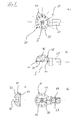
- FIG. 1 a bicycle according to the invention is partially shown, in which an inventive handlebar stem 1 and a seat post 3 according to the invention is provided with a pivot joint 5 according to the invention.
- the handlebar stem 1 is connected to a handlebar (not shown in detail), are coupled to the two gripping portions respectively via the pivot joint 5.
- FIG. 1 only one gripping portion 7 and a pivot joint 5 is shown.
- the seat post 3 is divided by a pivot joint 5 in a saddle remote, fixed pipe section and in a saddle near, pivoting pipe section, which allows different positions of the saddle 9.
- the pivot joint 5 can provide different pivotal positions for the respective gripping portion 7 and for the saddle 9, wherein the pivot joint is locked in the respective pivot position such that loading forces between the handlebar and the gripping portion 7 and the tube sections of the seat post up to 4 tons safely can be transmitted.
- pivot joint 5 As indicated in the introduction to the description.
- FIG. 2 is the pivot joint 5 according to the invention shown in a first embodiment.
- the pivot joint 5 according to the invention has as main components a first joint part 21 and a second joint part 23, which have an elongated arm extension 25, 27, to which a pipe or rod part of a frame structure (not shown) can be fastened.
- the first and second joint part 21, 23 each have a joint head half 29, 31, which is formed from a solid material.
- the arm extension 25, 27 and the respective Gelenkkopfliunn 29, 31 can be made of a piece of metal, in particular milled.
- Each condyle half 29, 31 defines a planar articulation surface 33, 35, which in the in FIG. 2 shown state each other and define the pivoting plane of the pivot joint 5.
- each a bore 37, 39 is formed, which are aligned with each other in the assembled state of the pivot joint, so that a rod-shaped carrier 41 can extend through the bores 37, 39 therethrough.
- the central axis of the bores 37, 39 define the pivot axis S of the pivot joint.
- a prestressed helical spring 47 is provided, the bias of which presses the second joint part 23 against the first joint part 21.
- An actuating lever 51 is screwed onto the end of the driver 41 opposite the driver head 45, a buffer washer 53 made of an elastomer material being arranged between the actuating lever 51 and the outside of the second articulated component 23.
- the driver 41 and in particular the driver head 45 is displaced depending on the depending on the thread pitch towards the actuating lever 51, whereby the joint parts 21, 23 can be braced against each other.
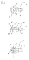
- the execution of the pivot joint 5 according to FIG. 3 differs from the design according to FIG. 2 in that instead of the rotary lever 51, a rotary ring 61 is used and that the driver head 45 is aligned with its longitudinal direction in the longitudinal direction of the arm extensions 25, 27.
- a recess 59 is formed on the torsion-side outer side of the joint head half 31 of the second joint part 23 in the region of the bore 39, in which complementary form the Pufferbeilagancy 53 is fitted.
- the driver 41 has next to the driver head 45, which has a part-spherical outer side 63, a bridging rod 65 which is made together with the driver head 45 in one piece.
- the bridging rod 65 has at the end facing away from the driver head 45 an external thread 67 on which the actuating lever 51 can be screwed.
- a hole 68 is provided which is intended to serve to receive a safety spindle against unintentional turning of the actuating lever 51.
- FIGS. 5a-d the second joint part 23 is shown in detail.
- An arm of a frame structure can be connected to the arm extension 27, wherein the arm of the arm structure can also be formed integrally with the arm extension 27.
- the arm extension 27 may have a threaded bore 69, via which the joint part 23 with one arm of the frame structure (not shown) is firmly screwed.
- an elongated recesses 75 is formed, in which the driver head 45 is retractable complementary shape, when the operating lever 51 is turned correspondingly and the driver 41, the second joint part 23 moves on the first joint part 21 mitikides.
- the outer side 63 of the driver head 45 forms an approximately hemispherical outer side 75 for the condyle 31 of the second joint part 23rd
- the receptacle 75 has a significantly larger section measurement than the bore 39, which ensures that the driver head 45 can take the joint part 23.
- the condyle 31 has at its joint surface 35 a plurality of blind holes 71 which lie on a circular path concentric to the pivot axis S of the pivot joint 5.
- the formed on the joint surface 35 twelve blind holes 71 serve to define the pivotal positions of the pivot joint 5 stationary and thus determine locking positions.
- a latching mechanism between the first and the second hinge part 21, 23 is realized with the help of blind holes and with the help of lugs that are complementary in shape to the holes formed and can be arranged on the articular surface 33 of the condyle 29 of the first joint part 21.
- the joint part 21 like the second joint part 23, has a threaded internal bore (not shown in any more detail) on the arm extension 25 in order to fasten the first joint part 21 to a skeleton arm structure (not shown). It is clear that the arm extension 25 can also be formed integrally with the arm of the arm structure.
- pins (not shown) are pressed, which form the lugs, which cooperate detent with the blind holes 71 in the second hinge part 23. It is clear that the lugs can also be formed integrally with the condyle 29.
- the bore 37 extends through which the bridging rod 65 of the driver 41 extends.
- a buffer shim receptacle 85 is formed in the region of the bore, in which the sheath washer 53 is securely held. In this way, the Pufferbeilageinflammatory 53 does not shift during the actuation of the actuating lever 51st
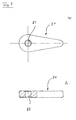
- the actuating lever 51 is shown in detail, which comprises at its wide portion a threaded hole 87 which cooperates with the external thread 67 of the bridging bar 65 of the driver 41 to brace over the driver 41, the hinge parts against each other when a pin positively in the pin holder 81st is included.
Landscapes
- Engineering & Computer Science (AREA)
- Mechanical Engineering (AREA)
- Pivots And Pivotal Connections (AREA)
Applications Claiming Priority (1)
| Application Number | Priority Date | Filing Date | Title |
|---|---|---|---|
| DE200810045045 DE102008045045A1 (de) | 2008-08-29 | 2008-08-29 | Schwenkgelenk für zwei miteinander zu koppelnde Bauteile |
Publications (1)
| Publication Number | Publication Date |
|---|---|
| EP2159151A1 true EP2159151A1 (fr) | 2010-03-03 |
Family
ID=41055351
Family Applications (1)
| Application Number | Title | Priority Date | Filing Date |
|---|---|---|---|
| EP20090010631 Withdrawn EP2159151A1 (fr) | 2008-08-29 | 2009-08-18 | Articulation de vélo pour un guidon et une tige de selle |
Country Status (2)
| Country | Link |
|---|---|
| EP (1) | EP2159151A1 (fr) |
| DE (1) | DE102008045045A1 (fr) |
Citations (3)
| Publication number | Priority date | Publication date | Assignee | Title |
|---|---|---|---|---|
| CH225697A (de) | 1942-10-01 | 1943-02-15 | Ohno Willy | Verstellbare Lenkstange, insbesondere für Fahrräder. |
| DE10216888A1 (de) | 2002-04-17 | 2003-11-06 | Selt Hermann Josef | Verstellbarer Zusatzgriff für Zweiradlenker |
| DE202004020002U1 (de) | 2004-03-09 | 2005-05-12 | Hsin Lung Accessories Co., Ltd, Hu Kou Hsiang | Verstellvorrichtung eines Fahrradlenkers |
Family Cites Families (1)
| Publication number | Priority date | Publication date | Assignee | Title |
|---|---|---|---|---|
| DE10155889B4 (de) | 2001-11-14 | 2004-12-02 | Alfred Karl Benedikt | Lenker für Fortbewegungsmittel, wie Fahrräder, Roller oder dergleichen |
-
2008
- 2008-08-29 DE DE200810045045 patent/DE102008045045A1/de not_active Withdrawn
-
2009
- 2009-08-18 EP EP20090010631 patent/EP2159151A1/fr not_active Withdrawn
Patent Citations (3)
| Publication number | Priority date | Publication date | Assignee | Title |
|---|---|---|---|---|
| CH225697A (de) | 1942-10-01 | 1943-02-15 | Ohno Willy | Verstellbare Lenkstange, insbesondere für Fahrräder. |
| DE10216888A1 (de) | 2002-04-17 | 2003-11-06 | Selt Hermann Josef | Verstellbarer Zusatzgriff für Zweiradlenker |
| DE202004020002U1 (de) | 2004-03-09 | 2005-05-12 | Hsin Lung Accessories Co., Ltd, Hu Kou Hsiang | Verstellvorrichtung eines Fahrradlenkers |
Also Published As
| Publication number | Publication date |
|---|---|
| DE102008045045A1 (de) | 2010-03-04 |
Similar Documents
| Publication | Publication Date | Title |
|---|---|---|
| EP2594473A1 (fr) | Dispositif à dérailleur pour un agencement de vitesses de vélo, notamment dispositif à dérailleur arrière | |
| DE1680556C2 (de) | Zerlegbarer Fahrradrahmen | |
| DE102010026691A1 (de) | Lenksäule für ein Fahrzeug | |
| EP2308749A1 (fr) | Potence de guidon pour un guidon de vélo | |
| DE202023104397U1 (de) | Lenkervorbau | |
| DE2854305A1 (de) | Zusammenklappbarer anhaenger fuer kraftfahrzeuge | |
| WO2007088002A1 (fr) | Bipode pour arme | |
| DE4325655A1 (de) | Selbsttätig sperrendes Gelenk, insbesondere Orthesengelenk | |
| EP3138738B1 (fr) | Dispositif de fixation de velo | |
| DE9013266U1 (de) | Zweirad mit einem höhenverstellbaren Sattel | |
| DE102009047821B4 (de) | Gleitbrettbindung mit Montagedeckel | |
| EP3800143A1 (fr) | Dispositif de positionnement précis d'une palette de transport | |
| DE102008045045A1 (de) | Schwenkgelenk für zwei miteinander zu koppelnde Bauteile | |
| DE102016217867A1 (de) | Transportvorrichtung für Gepäck und Verfahren zum Transport eines Gepäckstücks | |
| DE202023104401U1 (de) | Lenkervorbau | |
| DE102021125710B3 (de) | Kapp- und Zugsäge | |
| DE102009047820B4 (de) | Skibindung mit Hohlachse oder -welle | |
| DE10244277C1 (de) | Vorrichtung zur Einstellung der Beinspreizung eines Holzstativs, insbesondere eines Dreibeinstativs | |
| EP3868636A1 (fr) | Trottinette | |
| DE102009043802A1 (de) | Skibindung mit Gerippestruktur | |
| EP2329864B1 (fr) | Fixation de ski dotée d'une structure en cage | |
| DE102013108488A1 (de) | Faltrad | |
| EP2528804A1 (fr) | Tige de selle | |
| EP3786008B1 (fr) | Support | |
| WO2006097000A1 (fr) | Deux-roues a nacelle laterale |
Legal Events
| Date | Code | Title | Description |
|---|---|---|---|
| PUAI | Public reference made under article 153(3) epc to a published international application that has entered the european phase |
Free format text: ORIGINAL CODE: 0009012 |
|
| AK | Designated contracting states |
Kind code of ref document: A1 Designated state(s): AT BE BG CH CY CZ DE DK EE ES FI FR GB GR HR HU IE IS IT LI LT LU LV MC MK MT NL NO PL PT RO SE SI SK SM TR |
|
| AX | Request for extension of the european patent |
Extension state: AL BA RS |
|
| 17P | Request for examination filed |
Effective date: 20100817 |
|
| 17Q | First examination report despatched |
Effective date: 20130103 |
|
| GRAP | Despatch of communication of intention to grant a patent |
Free format text: ORIGINAL CODE: EPIDOSNIGR1 |
|
| RIC1 | Information provided on ipc code assigned before grant |
Ipc: F16C 11/04 20060101AFI20150414BHEP Ipc: B62J 1/08 20060101ALI20150414BHEP Ipc: B62K 21/16 20060101ALI20150414BHEP |
|
| INTG | Intention to grant announced |
Effective date: 20150506 |
|
| STAA | Information on the status of an ep patent application or granted ep patent |
Free format text: STATUS: THE APPLICATION IS DEEMED TO BE WITHDRAWN |
|
| 18D | Application deemed to be withdrawn |
Effective date: 20150917 |