EP2159189A1 - Revêtement d'assise pour selle de cheval - Google Patents
Revêtement d'assise pour selle de cheval Download PDFInfo
- Publication number
- EP2159189A1 EP2159189A1 EP08015332A EP08015332A EP2159189A1 EP 2159189 A1 EP2159189 A1 EP 2159189A1 EP 08015332 A EP08015332 A EP 08015332A EP 08015332 A EP08015332 A EP 08015332A EP 2159189 A1 EP2159189 A1 EP 2159189A1
- Authority
- EP
- European Patent Office
- Prior art keywords
- saddle
- saddle tree
- chamber
- seat
- tree
- Prior art date
- Legal status (The legal status is an assumption and is not a legal conclusion. Google has not performed a legal analysis and makes no representation as to the accuracy of the status listed.)
- Withdrawn
Links
- 230000008719 thickening Effects 0.000 claims abstract description 12
- 210000000988 bone and bone Anatomy 0.000 claims abstract 2
- XEEYBQQBJWHFJM-UHFFFAOYSA-N Iron Chemical compound [Fe] XEEYBQQBJWHFJM-UHFFFAOYSA-N 0.000 claims description 41
- 238000013016 damping Methods 0.000 claims description 23
- 229910052742 iron Inorganic materials 0.000 claims description 20
- 210000001217 buttock Anatomy 0.000 claims description 8
- 230000000087 stabilizing effect Effects 0.000 claims description 2
- 230000000284 resting effect Effects 0.000 claims 2
- 210000002105 tongue Anatomy 0.000 description 38
- 229910000831 Steel Inorganic materials 0.000 description 12
- 239000010959 steel Substances 0.000 description 12
- 239000000463 material Substances 0.000 description 11
- 238000005452 bending Methods 0.000 description 7
- 210000001624 hip Anatomy 0.000 description 7
- 241001465754 Metazoa Species 0.000 description 6
- 241001417534 Lutjanidae Species 0.000 description 5
- 239000002184 metal Substances 0.000 description 5
- 229910052751 metal Inorganic materials 0.000 description 5
- 239000003365 glass fiber Substances 0.000 description 4
- 239000004743 Polypropylene Substances 0.000 description 3
- 239000011152 fibreglass Substances 0.000 description 3
- 239000010985 leather Substances 0.000 description 3
- 239000004033 plastic Substances 0.000 description 3
- 229920003023 plastic Polymers 0.000 description 3
- -1 polypropylene Polymers 0.000 description 3
- 229920001155 polypropylene Polymers 0.000 description 3
- 229910000746 Structural steel Inorganic materials 0.000 description 2
- 206010052428 Wound Diseases 0.000 description 2
- 208000027418 Wounds and injury Diseases 0.000 description 2
- 230000006835 compression Effects 0.000 description 2
- 238000007906 compression Methods 0.000 description 2
- 239000006063 cullet Substances 0.000 description 2
- 239000006260 foam Substances 0.000 description 2
- 238000004519 manufacturing process Methods 0.000 description 2
- 239000004814 polyurethane Substances 0.000 description 2
- 210000003689 pubic bone Anatomy 0.000 description 2
- 239000012858 resilient material Substances 0.000 description 2
- 241000283074 Equus asinus Species 0.000 description 1
- 229920005830 Polyurethane Foam Polymers 0.000 description 1
- 239000007799 cork Substances 0.000 description 1
- 230000001419 dependent effect Effects 0.000 description 1
- 230000001771 impaired effect Effects 0.000 description 1
- 238000003801 milling Methods 0.000 description 1
- 239000002023 wood Substances 0.000 description 1
Images


Classifications
-
- B—PERFORMING OPERATIONS; TRANSPORTING
- B68—SADDLERY; UPHOLSTERY
- B68C—SADDLES; STIRRUPS
- B68C1/00—Saddling equipment for riding- or pack-animals
- B68C1/12—Bottom pads for saddles; Saddle cloths
- B68C1/126—Saddle covers or similar, e.g. to be placed between rider and saddle
-
- B—PERFORMING OPERATIONS; TRANSPORTING
- B68—SADDLERY; UPHOLSTERY
- B68C—SADDLES; STIRRUPS
- B68C1/00—Saddling equipment for riding- or pack-animals
- B68C1/02—Saddles
- B68C1/08—Saddles with pneumatic pads
Definitions
- the invention relates to a seat pad for padding a seat of a saddle and a saddle with such a seat pad.
- a foam such as polyurethane (PU) can be used for such a seat cushion.
- the seat comfort of the saddle is indeed improved by the known seat covers, however, the improvement achieved - especially in long rides - not considered sufficient.
- the invention is based on the object to improve a seat cushion for a saddle so that the comfort is significantly increased, and to provide a riding saddle with such a seat cushion.
- the object is achieved by a seat pad for padding a seat a saddle, with a saddle tree side to rest on a saddle tree.
- the seat cushion is characterized by a chamber open towards the side of the saddle tree for forming an air cushion under the buttocks of a riding person.
- the invention is based on the finding that the damping of the seat cushions according to the prior art for a given material depends on the thickness of the support and for a given thickness of the seat cushion and also predetermined material damping can not be adjusted.
- the invention is based on the idea to adjust the damping of the seat cushion by an air cushion. This allows adjustment of the damping at the same thickness and the same material of the support.
- a seat cushion according to the invention is, for example, directly, placed on the saddle tree a saddle and optionally glued.
- the air in the open to the saddle tree side chamber is initially compressed under load, such as by a seated riding person. If the chamber is at least largely closed tightly with the saddle tree, it forms at a certain compression, at least temporarily, a balance; the volume of the air cushion is then at least largely stable. If the chamber is not hermetically sealed to the outside, of course, air can escape, but also re-flow when the load is reduced.
- Any riding saddle can be made particularly comfortable with a seat cushion according to the invention.
- the damping can be adjusted.
- the exact geometry of the saddle tree or saddle plays no role, as long as the chamber can be at least partially sealed by the saddle tree itself or additional material between the saddle tree and seat cushion.
- the seat cushion according to the invention is made with PU foam.
- the shape of the chamber can be chosen comparatively freely, since the compression of the air takes place everywhere in the chamber substantially at the same time.
- the seat of the saddle is usually located between the waist and the rear edge of the saddle tree. Accordingly, it is preferable to design the seat pad such that the chamber or chambers come to lie between the waist and the rear edge of the saddle tree, ie towards the rear pommel.
- the seat cushion has two open to the saddle tree side chambers, which are each arranged under a buttock of the rider.
- the centers of these chambers are about 10 cm to 13 cm apart.
- the notifying party has determined through extensive testing that this distance is appropriate for most people of European descent.
- the buttocks of women are on average about 1 cm farther apart than the buttocks of men, but this can easily be taken into account by the width of the chambers.
- Seat pads are usually equipped with thickening, in particular so that the thickening or thickening of the full saddle between the waist of the saddle tree and its rear edge are.
- chambers according to the invention are arranged in such thickenings.
- each of the chambers has one, possibly rounded, rectangular basic shape. Accordingly, the air cushioning does not need to be tailored exactly to a specific person, because there is a margin for each of the chambers in the longitudinal direction and in the width direction.
- each of the chambers is between 2 cm and 5 cm long and between 1 cm and 3 cm wide.
- the longitudinal direction of each of the chambers is aligned along the longitudinal direction of the saddle tree.
- the object is also achieved by a saddle with a saddle tree and a seat cover according to the invention.
- the seat cover is placed on the saddle tree, possibly over intermediate material, so that an air exchange between the chamber or the chambers and their surroundings is braked by the support on the saddle tree.
- Saddle trees serve as a core or as a framework for a saddle to rest on the back of a riding or pack animal, such as a horse, a donkey or a pony; accordingly one speaks of a riding saddle or a transport saddle.
- the air exchange is slowed down by the contact of the chamber edges with the saddle tree.
- the seat pad is glued to the saddle tree.
- the seat cushion can be held so well and an air flow between the chamber and the environment can be prevented.
- the chambers are even hermetically sealed.
- the saddle tree has a chamber curvature for forming the chamber width of the saddle and a gullet iron for stabilizing the chamber curvature, which runs transversely to the length of the saddle tree along the chamber curvature, wherein the gullet iron is arranged at the top of the saddle tree.
- chamber curvature On their front side, that is to say on the side facing the head of the animal, saddles usually have the so-called chamber curvature. This serves to record the withers of the animal. If the withers are tall and narrow, the vaulting of the chamber must be high and narrow; if the withers are low and broad, the opposite is true.
- the width of the chamber curvature is also referred to as chamber width.
- the saddle tree as the framework of a saddle determined by its design, the chamber curvature and thus the chamber width of the saddle.
- the corresponding curvature of the saddle tree is therefore also referred to here as chamber curvature.
- the chamber width of a saddle is not necessary fix. It is known to adapt these by subsequent deformation individually to the animals.
- the saddle tree as a whole is exposed to great mechanical loads, the chamber buckling mainly spreading forces. Therefore, below the saddle tree, so on the bearing side, often a frame attached, which extends over a majority of the length and width of the saddle tree.
- the front section of such a frame, the so-called gullet supports from below the chamber vault.
- the gullet itself is preferably designed band-shaped over a large part of its length. It is thereby, also over a large part of its length, oriented transversely to the length of the saddle tree, so, with applied saddle, across the spine of the riding or Packtieres. The shape is adapted to the chamber curvature of the saddle tree.
- the gullet iron thus counteracts a spreading of the chamber curvature and keeps this burden of -.
- B. made of wood or plastic - body of the saddle tree largely far away.
- Gullets or the entire frame are usually made of metal, they can be made in particular of steel.
- the mechanical load of the gullet iron can be immense.
- the maximum possible thickness of the cullet is limited because otherwise it would stick out of the support side and injure the animal. Therefore, high strength requirements must be placed on the material of the gullet iron.
- Special steels are used to meet these material requirements. Corresponding steels are expensive and, if more disadvantageous, may not be available at will.
- This aspect is based on the additional idea that a gullet iron on the one hand does not have to be integrated into a frame and on the other hand can sufficiently support the saddle tree, if it is not arranged on the support side, but on the side facing away from the support side top of the saddle tree. Again, the gullet can counteract a spread of chamber vault.
- an overhead gullet can be easily varied in thickness, because there is no limit to the top - the seat for a riding person is located behind the chamber vault.
- the flexural rigidity increases cubically with the strength; due to this relationship, the required flexural rigidity can be easily adjusted. Also, a less resilient material for the saddle tree body can be used if only the top arranged gullet iron is designed sufficiently thick.
- the chamber width can be adjusted more easily in the case of corresponding saddle trees.
- the chamber width is adjusted by bending the chamber curvature.
- the saddle tree is clamped in a suitably designed vice and possibly facilitates bending with a heat source.
- the saddle trees of the prior art must be paid much attention to the orientation of the saddle tree when inserting, since the gullet is otherwise easily warped.
- the force distribution succeeds more uniformly, accordingly, the gullets do not distort so easily and the adjustment of the chamber width can also be made more accurately.
- the chamber width can thus be set easier than before and thus also locally, for example at a dealer; Submitting to the manufacturer is largely unnecessary.
- corresponding gullets are preferably not integrated into a frame.
- Said gullet iron run transversely to the longitudinal direction of the saddle tree; accordingly, one end of the cork blade is on the left and one end of the cullet is on the right of the center line along the longitudinal direction of the saddle tree. It is preferred to provide in each case a stirrup-belt holder in the region of these ends of the gullet iron. Ideally, these are integrally formed from the gullet iron.
- stirrup-belt holder As an alternative to the one-piece design of the stirrup-belt holder from the gullet iron, it is preferable to make the stirrup-belt holder exchangeable, for example in order to respond to customer requests.
- the stirrup-belt holders can be attached to the saddle tree or to the gullet by riveting or screwing.
- the stirrup-belt holder has a crash spring, such as a snapper; This applies both to the one-piece and the interchangeable design of the stirrup-belt holder.
- the stirrup-belt holder may be surrounded by a sleeve.
- connection between gullet and saddle tree serves only to fix the gullet.
- the gullet is therefore only riveted to the saddle tree. This is structurally very simple.
- a lower gullet may be located at the bottom of the chamber vault of the saddle tree, with or without being bound into a frame.
- Saddle trees are usually waisted, so that the vault on the left and right each forms a wing. It is preferred to cut the chamber vault between the two wings from the edge of the saddle tree. This can be done approximately from the front edge of the saddle tree, preferably centrally in the apex region, ie in the region of the greatest curvature of the curvature, and along the center line. Such cuts facilitate the bending of the saddle tree for adjusting the chamber width. Particularly advantageous are two parallel cuts, which extend beyond the gullet iron to a maximum of the gullet iron, whereby a sufficient deformability is ensured, however, the bending stiffness is not impaired too much.
- the seat surface of the saddle tree has an incision with a profile such that a more flexible tongue is formed, which extends in a central region of the seat surface.
- the damping can be adjusted during manufacture, cf. DE 20 2007 006 992 U1 ,
- the damping can be adjusted by the design of the tongue alone only to a limited extent.
- the areal extent of the tongue and the achieved damping interact with each other.
- a large tongue requires soft cushioning.
- an additional damping element is preferably used. This is attached to the tongue to the saddle tree and can thus dampen the flexibility of the tongue. In particular, so large tongues can be realized with a tight damping.
- the damping element may be, for example, a steel spring which is fastened to the underside, that is to say the support side, of the saddle tree in contact with the tongue.
- the steel spring may be attached to the saddle tree at one or two points, for example via a screw connection, as known from ski boots for attachment to the shell.
- a particularly preferred damping element, a belt, is presented below.
- the saddle tree itself may also consist of a metal or a plastic, in particular a glass fiber reinforced plastic, ideally made of 2% glass fiber reinforced polypropylene (PPH).
- a metal or a plastic in particular a glass fiber reinforced plastic, ideally made of 2% glass fiber reinforced polypropylene (PPH).
- the incision can be realized in any way, such as milling.
- the tongue is preferably disposed in the saddle tree below the seating surface of the saddle in a central region thereof. It is preferred if the incision for forming the tongue is arranged completely in the surface of the saddle tree, thus representing no incision from the edge.
- the damping element is fastened to the saddle tree with two fasteners, the tongue lying between these fastenings. This may be about the two attachments on the underside of the saddle tree or even one of the fasteners on the top and the other at the bottom of the saddle tree.
- the damping element is guided through the incision, which is preferably arranged between at least two fastenings of the damping element.
- a first of the fasteners on the support side of the saddle tree and the second of the fasteners on the seat side of the saddle tree is arranged.
- the damping element is ideally with the first attachment to the support side in the rear of the saddle tree, ie behind the saddle, attached, for example.
- the damping element is ideally with the first attachment to the support side in the rear of the saddle tree, ie behind the saddle, attached, for example.
- the rear edge of the saddle tree passed through the incision and with the second attachment to the top of the saddle tree, in front of the tongue, thus on the foreland side, attached.
- a bending of the tongue downwards can be counteracted particularly well.
- the saddle-tree-side attachment is preferably arranged in front of the tongue and the seat-side attachment preferably behind the tongue.
- the damping element is a, in particular elastic, belt.
- a belt as it is known from the production of upholstered furniture with spring core, a so-called padded belt.
- a spring in particular a steel spring, may be preferred.
- the incision preferably has the shape of a, in particular rounded, "V".
- the tip of the "V” preferably points to the front; so the pubic bone can be relieved particularly well.
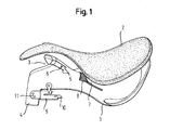
- Fig. 1 shows - with some supervision - a saddle tree 1 from the side. Above the saddle tree 1, a seat pad 2 is shown. Seat cover 2 and saddle tree 1 lie, except for their distance, to each other, as in a complete saddle (not shown).
- the saddle tree 1 is made of polypropylene (PPH) with 2% glass fibers.
- the seat cover 2 is made of polyurethane (PU) foam.
- the saddle tree 1 forms at its front end, left in the figure, a chamber bulge 3 for receiving the withers of a mount.
- the Kammervölbung 3 runs left and right, seen from the center line of the saddle tree in the longitudinal direction, in each case a wing 4.
- two parallel cuts 5 are shown, which begin at the front end of the saddle tree and extend a few centimeters substantially parallel to the center line in the saddle tree 1 in. These two incisions 5 facilitate a deformation of gullets (see. Fig. 2 and 4 ) for adjusting the chamber width.
- a rivet 6 is arranged for fixing an additional head iron (not shown; Fig. 2 ) below the chamber vault 3.
- the seat support 2 is placed on the saddle tree 1, wherein between the seat cover 2 and the saddle tree 1 on the chamber curvature 3 a gullet iron (see. Fig. 4 ) is attached.
- a flexible tongue 7 is shown to increase the seating comfort.
- the tongue 7 is realized by a rounded "V" shaped cut-out in the saddle tree (better to see in FIG Fig. 2 ).
- the tongue 7 is arranged so that the tip of the "V” points to the chamber curvature and is approximately equal to the waist of the saddle tree and the broad side of the "V” is approximately equal to the rear maximum width of the saddle tree, so that when riding the Pubic bone is relieved.
- An elastic padded belt 8 is used for damping the flexible tongue 7.
- the padded belt 8 is first mounted on top of the saddle tree 1, in front of the tongue 7. Next, the padded belt 8 is guided by the cutout under the tongue 7 and also attached to the bottom of the saddle tree 1 (see. Fig. 2 ).
- stirrup-belt holder 9 is releasably secured, here via a riveting 11, for example. But also via a screw (not shown). So that a stirrup leather (not shown) does not accidentally slip out of the stirrup leather holder 9, it has a snap closure 10, or snapper for short. In the horizontal orientation shown, the snapper 10 readily allows a stirrup belt to be inserted into the stirrup-belt holder 9. If the snap-action catcher 10 points upward, it will resist the sliding out of the stirrup-belt.
- the stirrup-belt holder 9 may be surrounded by a sleeve (not shown).
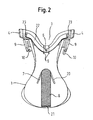
- Fig. 2 shows the saddle tree Fig. 1 from underneath.
- the upholstery belt 8 is guided by the "V" -shaped and completely in the surface of the saddle tree 1 cutout 20, while supporting the tongue 7 from below and is attached 21 in the rear of the saddle tree.
- a steel spring (not shown) may be attached to the underside of the saddle tree 1 in contact with the tongue 7.
- the steel spring for example, is fastened in front of and behind the tongue 7. Possibly. It is even enough to fasten the steel spring at just one point.
- the additional lower head iron 22 made of steel, which in conjunction with an upper gullet iron (see. Fig. 4 ) the chamber vault 3 supports.
- the lower gullet 22 is fixed via a riveting 6 and 23 on the saddle tree 1.
- Fig. 3 shows the saddle tree 1 from the FIGS. 1 and 2 in a top view. Here you can see well the arrangement of the tongue 7, and that the padded belt 8 is secured 30 before the tongue 7.
- Fig. 4 shows the front part of another saddle tree 1, which also has a chamber curvature 3 and 4 wings.
- this saddle tree 1 consists of PPH with 2% glass fibers.
- a seat cover 2 as in Fig. 1 is shown, is folded away in the front area to reveal the view of a steel iron 41 steel.
- This gullet 41 is disposed on the chamber curvature 3 and counteracts a spreading of the same.
- the gullet 41 extends over a large part of its length band-shaped transversely to the length of the saddle tree 1 at the chamber vault 3 along.
- a stirrup belt holder 9 is formed integrally with snapper 10.
- the overhead chisel 41 is fixed to the saddle tree 1 via rivets 42.
- the head 41 is made of common conventional structural steel and has a thickness in the range of 1 mm to 10 mm.
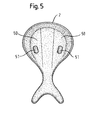
- Fig. 5 is the seat cushion 2 from the FIGS. 1 and 4 shown from below. Between the waist and the rear end, the seat cushion 2 has two substantially parallel thickenings 50 in the longitudinal direction. In the front region of these thickenings 50, ie between the waist and the maximum width of the seat cushion 2, a downwardly open, rounded rectangular chamber 51 is introduced into each of the thickenings 50.
- the chambers 51 are arranged so that they usually come to lie below the buttocks of a riding person in a full saddle.
- the chambers are about 4 cm long and 2.5 cm wide; their centers are about 12 cm apart.
- the seat cover 2 is glued to one of the saddle trees 1 shown above.
- the air cushion then contained in the chambers 51 increase the seating comfort.
Landscapes
- Engineering & Computer Science (AREA)
- Mechanical Engineering (AREA)
- Mattresses And Other Support Structures For Chairs And Beds (AREA)
Priority Applications (1)
| Application Number | Priority Date | Filing Date | Title |
|---|---|---|---|
| EP08015332A EP2159189A1 (fr) | 2008-08-29 | 2008-08-29 | Revêtement d'assise pour selle de cheval |
Applications Claiming Priority (1)
| Application Number | Priority Date | Filing Date | Title |
|---|---|---|---|
| EP08015332A EP2159189A1 (fr) | 2008-08-29 | 2008-08-29 | Revêtement d'assise pour selle de cheval |
Publications (1)
| Publication Number | Publication Date |
|---|---|
| EP2159189A1 true EP2159189A1 (fr) | 2010-03-03 |
Family
ID=40260802
Family Applications (1)
| Application Number | Title | Priority Date | Filing Date |
|---|---|---|---|
| EP08015332A Withdrawn EP2159189A1 (fr) | 2008-08-29 | 2008-08-29 | Revêtement d'assise pour selle de cheval |
Country Status (1)
| Country | Link |
|---|---|
| EP (1) | EP2159189A1 (fr) |
Cited By (1)
| Publication number | Priority date | Publication date | Assignee | Title |
|---|---|---|---|---|
| GB2501201A (en) * | 2009-09-02 | 2013-10-16 | Total Saddle Solutions Ltd | Saddle with a seat |
Citations (7)
| Publication number | Priority date | Publication date | Assignee | Title |
|---|---|---|---|---|
| DE9411491U1 (de) * | 1994-07-15 | 1994-09-29 | Georg Kieffer Sattlerwarenfabrik GmbH, 81929 München | Sattelpolster zum Einbau in Reitsättel |
| US5517808A (en) * | 1994-12-06 | 1996-05-21 | Schleese; Jochen | Saddle tree |
| DE20107504U1 (de) * | 2001-05-02 | 2002-06-20 | Bauer, Anton, 90602 Pyrbaum | Reitsattel mit einem Sattelbaum |
| US6434916B1 (en) * | 2000-04-26 | 2002-08-20 | Steven C. Tucker | Shock absorbing anatomically sculptured saddle seat |
| FR2885614A1 (fr) * | 2005-05-13 | 2006-11-17 | Arconnerie Soc Par Actions Sim | Arcon pour selle d'equitation, procede de fabrication d'une selle, moyen utilise et selle realisee |
| DE202007006992U1 (de) | 2007-05-15 | 2007-08-02 | Georg Kieffer Sattlerwarenfabrik Gmbh | Schwingungsdämpfungssystem bei Sattelbäumen |
| DE202007010745U1 (de) * | 2007-08-02 | 2007-10-25 | Georg Kieffer Sattlerwarenfabrik Gmbh | Einstellbares Schwingungsdämpfungssystem für Reitsattelbäume |
-
2008
- 2008-08-29 EP EP08015332A patent/EP2159189A1/fr not_active Withdrawn
Patent Citations (7)
| Publication number | Priority date | Publication date | Assignee | Title |
|---|---|---|---|---|
| DE9411491U1 (de) * | 1994-07-15 | 1994-09-29 | Georg Kieffer Sattlerwarenfabrik GmbH, 81929 München | Sattelpolster zum Einbau in Reitsättel |
| US5517808A (en) * | 1994-12-06 | 1996-05-21 | Schleese; Jochen | Saddle tree |
| US6434916B1 (en) * | 2000-04-26 | 2002-08-20 | Steven C. Tucker | Shock absorbing anatomically sculptured saddle seat |
| DE20107504U1 (de) * | 2001-05-02 | 2002-06-20 | Bauer, Anton, 90602 Pyrbaum | Reitsattel mit einem Sattelbaum |
| FR2885614A1 (fr) * | 2005-05-13 | 2006-11-17 | Arconnerie Soc Par Actions Sim | Arcon pour selle d'equitation, procede de fabrication d'une selle, moyen utilise et selle realisee |
| DE202007006992U1 (de) | 2007-05-15 | 2007-08-02 | Georg Kieffer Sattlerwarenfabrik Gmbh | Schwingungsdämpfungssystem bei Sattelbäumen |
| DE202007010745U1 (de) * | 2007-08-02 | 2007-10-25 | Georg Kieffer Sattlerwarenfabrik Gmbh | Einstellbares Schwingungsdämpfungssystem für Reitsattelbäume |
Cited By (2)
| Publication number | Priority date | Publication date | Assignee | Title |
|---|---|---|---|---|
| GB2501201A (en) * | 2009-09-02 | 2013-10-16 | Total Saddle Solutions Ltd | Saddle with a seat |
| GB2501201B (en) * | 2009-09-02 | 2014-02-26 | Total Saddle Solutions Ltd | Improvements in or relating to saddles |
Similar Documents
| Publication | Publication Date | Title |
|---|---|---|
| EP2660189B1 (fr) | Dispositif pour un revêtement d'assise d'une monture ou d'un animal de transport | |
| DE1554084B2 (de) | Sitz, insbesondere Kraftfahrzeugsitz | |
| WO1993004892A1 (fr) | Partie siege d'un siege de vehicule | |
| CH662257A5 (de) | Arbeitsstuhl. | |
| DE102017123727A1 (de) | Fahrradsattel | |
| EP2159187A1 (fr) | Arçon de selle doté d'une arcade | |
| DE202012104731U1 (de) | Sattel | |
| EP2159188A1 (fr) | Arçon de selle doté d'une languette flexible | |
| DE102016009753A1 (de) | Rückentrage und Verlängerungsplatte für eine Rückentrage | |
| EP2159189A1 (fr) | Revêtement d'assise pour selle de cheval | |
| EP1103517B1 (fr) | Arçon de selle muni d'éléments porteurs élastiques | |
| EP0589071B1 (fr) | Dispositif pour retenir un passager de petite taille à un siège de véhicule équipé d'une ceinture de sécurité | |
| DE202010011046U1 (de) | Sattelpad | |
| DE102012106008A1 (de) | Vorrichtung für eine Sitzauflage eines Reit- oder Transporttieres | |
| DE4414789C2 (de) | Sattel | |
| EP1752414B1 (fr) | Tapis de selle avec un dispositif à ressort à lame pour la stabilisation et la répartition de pression | |
| EP3034459B1 (fr) | Selle | |
| DE102012025754A1 (de) | Vorrichtung für eine Sitzauflage eines Reit- oder Transporttieres | |
| DE10029843B4 (de) | Fahrzeugsitz, insbesondere Kart-Sitz | |
| WO2022078879A1 (fr) | Coussin de selle | |
| EP2886509A1 (fr) | Tapis de monte à cru destiné à être appliqué sur une monture | |
| DE102017104790B4 (de) | Sattel für Reittiere | |
| DE102011000084A1 (de) | Rückenstütze | |
| DE102020006800A1 (de) | Sattel für Reittiere mit Filzbaum und Pausche | |
| EP0756266A2 (fr) | Dispositif porteur pour réceptacles d'instruments |
Legal Events
| Date | Code | Title | Description |
|---|---|---|---|
| PUAI | Public reference made under article 153(3) epc to a published international application that has entered the european phase |
Free format text: ORIGINAL CODE: 0009012 |
|
| AK | Designated contracting states |
Kind code of ref document: A1 Designated state(s): AT BE BG CH CY CZ DE DK EE ES FI FR GB GR HR HU IE IS IT LI LT LU LV MC MT NL NO PL PT RO SE SI SK TR |
|
| AX | Request for extension of the european patent |
Extension state: AL BA MK RS |
|
| STAA | Information on the status of an ep patent application or granted ep patent |
Free format text: STATUS: THE APPLICATION HAS BEEN WITHDRAWN |
|
| 18W | Application withdrawn |
Effective date: 20100610 |