EP2159326A2 - Système de retenue de véhicule - Google Patents
Système de retenue de véhicule Download PDFInfo
- Publication number
- EP2159326A2 EP2159326A2 EP09010424A EP09010424A EP2159326A2 EP 2159326 A2 EP2159326 A2 EP 2159326A2 EP 09010424 A EP09010424 A EP 09010424A EP 09010424 A EP09010424 A EP 09010424A EP 2159326 A2 EP2159326 A2 EP 2159326A2
- Authority
- EP
- European Patent Office
- Prior art keywords
- restraint system
- vehicle restraint
- guard rails
- reinforcing profiles
- tilting elements
- Prior art date
- Legal status (The legal status is an assumption and is not a legal conclusion. Google has not performed a legal analysis and makes no representation as to the accuracy of the status listed.)
- Granted
Links
Images


Classifications
-
- E—FIXED CONSTRUCTIONS
- E01—CONSTRUCTION OF ROADS, RAILWAYS, OR BRIDGES
- E01F—ADDITIONAL WORK, SUCH AS EQUIPPING ROADS OR THE CONSTRUCTION OF PLATFORMS, HELICOPTER LANDING STAGES, SIGNS, SNOW FENCES, OR THE LIKE
- E01F15/00—Safety arrangements for slowing, redirecting or stopping errant vehicles, e.g. guard posts or bollards; Arrangements for reducing damage to roadside structures due to vehicular impact
- E01F15/02—Continuous barriers extending along roads or between traffic lanes
- E01F15/04—Continuous barriers extending along roads or between traffic lanes essentially made of longitudinal beams or rigid strips supported above ground at spaced points
- E01F15/0407—Metal rails
- E01F15/0438—Spacers between rails and posts, e.g. energy-absorbing means
-
- E—FIXED CONSTRUCTIONS
- E01—CONSTRUCTION OF ROADS, RAILWAYS, OR BRIDGES
- E01F—ADDITIONAL WORK, SUCH AS EQUIPPING ROADS OR THE CONSTRUCTION OF PLATFORMS, HELICOPTER LANDING STAGES, SIGNS, SNOW FENCES, OR THE LIKE
- E01F15/00—Safety arrangements for slowing, redirecting or stopping errant vehicles, e.g. guard posts or bollards; Arrangements for reducing damage to roadside structures due to vehicular impact
- E01F15/02—Continuous barriers extending along roads or between traffic lanes
- E01F15/04—Continuous barriers extending along roads or between traffic lanes essentially made of longitudinal beams or rigid strips supported above ground at spaced points
- E01F15/0407—Metal rails
- E01F15/0423—Details of rails
Definitions
- the invention relates to a vehicle restraint system according to the features in the preamble of claim 1.
- Such a vehicle restraint system is used in the DE 1 784 602 A disclosed.
- W-shaped guard rails are releasably connected to a protective barrier strand in cross-section.
- the guard rails are coupled via fixing screws with two opposing front panels having box-like spacer brackets, which in turn are fastened by means of predetermined breaking screws to vertical posts.
- the tilting elements have over more than half the height of the guardrails reaching, in the horizontal direction flexible web on. They therefore behave like joints when a vehicle collides.
- the crash barriers should be able to be pressed back on a greater length, without the vehicle breaks through the crash barriers.
- the invention is - based on the prior art - the object to provide an incorporated into the coupling region between a guard rail and a distance console of a vehicle restraint tilting element which prevents a catapult-like throwing away a distance console when a vehicle gets under the guard rail and a post contacted.
- the tilting elements interspersed by the fixing screws and releasably integrated between the spacer brackets and the guardrails are now configured disk-like and have central recesses and, on the sides facing the guardrails, in each case a vertically extending bead are provided laterally of the beads in the direction of the distance brackets inclined inclined surfaces.
- the tilting elements can be provided directly between the protective planks facing outer surfaces of the end plates of the distance brackets and the outer facing sides of the floors of the guard rails.
- the tilting elements expediently receive a diameter which corresponds approximately to the height of the guardrails facing front plates of the distance brackets. This height is also approximated to the width of the outsides of the floors of the crash barrier.
- the beads in cooperation with the inclined surfaces, form supports by means of which, in the event of a vehicle collision, the distance brackets can roll off to the side in the sense of limited compliance.
- the tilting elements are set flat on the distance brackets.
- the side of the beads provided inclined surfaces support a directional rolling behavior of the distance brackets.
- the inclined surfaces may be flat or convex.
- the measures according to the invention can not be prevented after destroying the predetermined breaking screw between a post and a distance console, that the impacting vehicle also contacts the distance console, however, due to the tilting element, the distance bracket to avoid the vertical pivot axis laterally.
- This flexibility behavior of the spacer bracket significantly reduces the tensile force, which tends to destroy the fixing screw and thus tear off the spacer bracket and wegzuschleudern the guard rail.
- the fixing screw in the coupling region is made high-strength, which thus already creates a considerable resistance against destruction and connects the distance bracket further with the protective barrier strand.
- the tilting elements may be configured on the sides facing away from the beads to form recesses lattice-like.
- the lattice-like configuration is formed by intersecting ribs which, with the formation of diamond-shaped recesses, partially tangent to an inner annular collar delimiting the central recess in the tilting elements and open into a circumferentially closed outer annular collar.
- the recesses may be formed as recesses or as the tilting elements on the entire thickness at least next to the beads passing through openings.
- the tilting elements are made of plastic.
- the tilting elements are made of polyurethane.
- a suitable material for the tilting elements has a hardness between 40 Shore and 80 Shore.
- the tilting elements are formed from a UV and weather-resistant material.
- the invention proves - as explained above - in principle already then advantageous if the cross-sectionally W-shaped protective barriers are connected to the integration of the tilting elements directly to the spacer brackets.
- the reinforcing profiles have a trapezoidal design of webs and adjoining diverging legs. These legs surround the legs of the guard rails and are connected to these.
- End sides of the legs are preferably beveled flanges provided which are applied to the post facing the inner surfaces of the outer limbs of the guard rails and connected thereto.
- the legs of the crash barrier and the reinforcement profiles are then at a distance from each other. Spacers are provided between the floors of the crash barriers and the webs of the reinforcing profiles. These can consist of a suitable plastic.
- the flanges of the reinforcing profiles are in this case facing away from each other and facing the posts.
- the fixing screws also enforce the spacers and the webs of the reinforcing profiles.
- the webs of the reinforcing profiles are expediently provided with longitudinal slots.
- the spacers between the floors of the crash barriers and the webs of the reinforcing profiles can be equipped with slots and additional round holes.
- the slots are used to pass the fixing and coupling screws, while the round holes are used for the passage of mounting aids in the form of round rods.
- the spacers can also be designed like a disk and be provided with triangular openings, with a corner of each opening facing upward. In these triangular openings, the slots and round holes of the basic design of the spacers are then to some extent summarized.
- a strip-like spacer is used according to the invention where two guard rails are to be connected to each other and to a post.
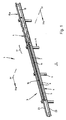
- FIGS. 1 . 2 . 4 and 7 is denoted by 1 a vehicle restraint system, which is set up at the edge of road 2, in particular motor vehicles, (lanes).
- a vehicle restraint system which is set up at the edge of road 2, in particular motor vehicles, (lanes).
- the vehicle restraint system 1 initially comprises a guard rail 3 of releasably interconnected, in cross-section W-shaped steel crash barriers 4.
- FIGS. 1 . 3 and 4 can be seen extending at each guardrail 4 of a largely rectilinear and in the application shown vertically extending bottom 5 of two mutually divergent inner leg 6, followed by two also mutually divergent outer leg 7.
- the outer leg 7 is followed by short bends 8.
- the outer legs 7 point in the direction of steel posts 9, which are rammed into the ground 10.
- the posts 9 have a C-shaped cross section in the embodiment, wherein the open side of the cross section faces away from the protective barrier strand 3 ( Figures 2 . 5 . 6 and 7 ).
- FIG. 3 still recognize that in the floors 5 of the guard rails 4 are provided at a distance from each other slots 14.
- the vehicle restraint system 1 further comprises in cross-section trapezoidal steel reinforcement profiles 15 (FIG. FIG. 10 ), 15a ( FIGS. 1 to 7 and 11 ), which are shot against each other and releasably connected together in the overlapping zones 16.
- a short length region 18 is bent, namely by the thickness of the material of the reinforcing profiles 15, 15a (FIG. FIG. 3 ).
- the end of the adjacent reinforcing profile 15, 15a can be coupled to the bent-over longitudinal section 18, so that the surfaces of all the reinforcing profiles 15, 15a facing away from the posts 9 lie in the same planes.
- the reinforcing profiles 15, 15a are detachably connected to each other via holes 20 provided in their webs 19 and via bores 22 provided in the webs 19 of diverging legs 22 by means of not-illustrated fillister head bolts and nuts. End of the legs 21 of the reinforcing profiles 15a close to each other and facing away from the post 9 flanges 23 at.
- a disc-like spacers 24 may be provided ( FIGS. 4 and 5 ). These have slots 25 and in the installation situation above the slots 25 round holes 26.
- the spacers 24 may consist of a suitable plastic.
- FIG. 12 can the spacers 24a but also have triangular openings 27, wherein in the installation situation, a corner 28 of the openings 27 is directed upward.
- tab-like spacer 24b is used at the end of the guard rails 4.
- reinforcing profiles 15, 15a in the area between two posts. 9 overlap while the guard rails 4 overlap in the area of a post 9.
- the tab-like spacers 24b at the ends of round holes 29 and in the central region triangular openings 30, in which a corner 31 is directed upward in the installation situation.
- the function of the triangular openings 27, 30 in the spacers 24a, 24b according to the FIGS. 12 and 13 corresponds to the functions of the elongated holes 25 and the round holes 26 in the spacers 24 according to the FIG. 5 ,
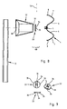
- FIGS. 4 . 6 and 8 to 11 is in the coupling regions KB between the webs 19 of the reinforcing profiles 15, 15a and box-like spacer brackets 32 each arranged a disc-like tilting member 33 made of polyurethane.
- the diameter of the tilting elements 33 corresponds approximately to the height of the posts 9 facing away from end plates 37 of the spacer brackets 32.
- Each tilting element 33 has a vertically in the installed position extending bead 34, which forms a vertical pivot axis SA.
- the bead 34 is adjoined laterally by two inclined oblique surfaces 35 sloping towards the distance bracket 32.
- the possibly rounded bead 34 is penetrated by a central recess 36.
- the tilting element 33 is connected via the side facing away from the bead 34 surface with the face plate 37.
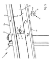
- the distance brackets 32 are trapezoidal in both the plan view and in the side view. They each consist of two U-shaped folded and then welded together steel sheets. As a result, the aforementioned end plates 37 and further end plates 38 are formed, in which the posts 9 facing away from end plates 37 oblong rectangular and the posts 9 facing end plates 38 are designed vertically rectangular.
- the distance brackets 32 are on the vertically aligned end plates 38 and not illustrated in detail by means of in the FIG. 4 in dotted lines Line guide shown predetermined breaking screws 39 connected to the upper ends of the post 9.
- FIG. 5 In the post 9 facing away from the end plates 37 of the spacer brackets 32 two adjacent holes 40, 41 are provided ( Figures 5 and 6 ).
- the one bore 40 serves to define the reinforcing profiles 15, 15a on the spacer brackets 32.
- one of the FIG. 5 recognizable coupling screw 42 inserted through a hole in a tab 43 which abuts the side facing away from the post 9 of the web 19 of the reinforcing profile 15, 15a, then through a slot 44 in the web 19 and finally through the bore 40 in the face plate 37 of the spacer console 32nd guided.
- a nut 45 FIG. FIG. 7
- the other hole 41 in the end plate 37 of the spacer console 32 serves to establish the guard rails 4 to the spacer brackets 32.
- a turned on the shank of the fixing screw 46 nut 47 then connects the parts together.
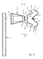
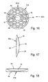
- FIGS. 14 to 18 another embodiment of a disc-like tilting element 33a is shown. Its general contour corresponds to that of the tilting element 33 according to FIGS FIGS. 4 . 6 and 8 to 11 , That is, it has a bead 34, two lateral inclined surfaces 35 and a central recess 36.
- the bead 34 may be flat or curved.
- the inclined surfaces 35 may also be flat or convex.
- the tilting element 33a is configured on the side 48 facing away from the bead 34 to form diamond-shaped recesses 49 in the manner of a lattice.
- This configuration is formed by intersecting ribs 50.
- the width of the ribs 50 is narrower than the width of the recesses 49 between two mutually parallel ribs 50.
- the ribs 50 partially tangent to the central recess 36 defining inner annular collar 51 and open into a circumferentially closed outer annular collar 52nd
- Figures 14 and 16 can the recesses 49 at least in the region of the inclined surfaces 35 adjacent to the bead 34 in contrast to the embodiment of the FIG. 15 be designed as a continuous openings.
Landscapes
- Engineering & Computer Science (AREA)
- Architecture (AREA)
- Civil Engineering (AREA)
- Structural Engineering (AREA)
- Refuge Islands, Traffic Blockers, Or Guard Fence (AREA)
- Fittings On The Vehicle Exterior For Carrying Loads, And Devices For Holding Or Mounting Articles (AREA)
Applications Claiming Priority (1)
| Application Number | Priority Date | Filing Date | Title |
|---|---|---|---|
| DE200810039850 DE102008039850B3 (de) | 2008-08-27 | 2008-08-27 | Fahrzeugrückhaltesystem |
Publications (3)
| Publication Number | Publication Date |
|---|---|
| EP2159326A2 true EP2159326A2 (fr) | 2010-03-03 |
| EP2159326A3 EP2159326A3 (fr) | 2013-02-27 |
| EP2159326B1 EP2159326B1 (fr) | 2013-10-23 |
Family
ID=41381655
Family Applications (1)
| Application Number | Title | Priority Date | Filing Date |
|---|---|---|---|
| EP20090010424 Active EP2159326B1 (fr) | 2008-08-27 | 2009-08-13 | Système de retenue de véhicule |
Country Status (2)
| Country | Link |
|---|---|
| EP (1) | EP2159326B1 (fr) |
| DE (1) | DE102008039850B3 (fr) |
Cited By (2)
| Publication number | Priority date | Publication date | Assignee | Title |
|---|---|---|---|---|
| US20180282957A1 (en) * | 2015-04-02 | 2018-10-04 | Arcelormittal | Spacer for Road Safety Barrier |
| IT201900024988A1 (it) * | 2019-12-20 | 2021-06-20 | Tsl Engineering Soc A Responsabilita Limitata | Dispositivo di fissaggio per barriere stradali di sicurezza |
Families Citing this family (2)
| Publication number | Priority date | Publication date | Assignee | Title |
|---|---|---|---|---|
| DE102014107874A1 (de) | 2014-06-04 | 2015-12-17 | SGGT Straßenausstattungen GmbH | Fahrzeugrückhaltesystem |
| EP4686785A1 (fr) | 2024-07-30 | 2026-02-04 | Meiser Straßenausstattung GmbH | Système de retenue de véhicule |
Citations (2)
| Publication number | Priority date | Publication date | Assignee | Title |
|---|---|---|---|---|
| DE1784602A1 (de) | 1967-08-29 | 1971-09-02 | Vmw Ranshofen Berndorf Ag | Befestigung fuer Leitvorrichtungen,insbesondere Strassenleitschienen fuer Mittelstreifen |
| EP1908882A1 (fr) | 2006-09-29 | 2008-04-09 | SPIG Schutzplanken-Produktions-Gesellschaft mbH & Co.KG | Agencement de profilés de protection |
Family Cites Families (5)
| Publication number | Priority date | Publication date | Assignee | Title |
|---|---|---|---|---|
| US2438991A (en) * | 1942-01-02 | 1948-04-06 | Eugene V Camp | Highway traffic guard |
| AT207878B (de) * | 1958-08-23 | 1960-03-10 | Semperit Ag | Elastische Befestigung von Leitschienen für Fahrbahnbegrenzungen |
| DE1959004A1 (de) * | 1969-11-25 | 1971-05-27 | Josef Wertmann | Vorrichtung zur Befestigung einer Strassenleitplanke an einem Pfosten |
| US5195727A (en) * | 1992-03-18 | 1993-03-23 | Liao Wan Ming | Tubular shock-absorbing device for a rail |
| DE102004039792B4 (de) * | 2004-08-16 | 2007-01-11 | Spig Schutzplanken-Produktions-Gesellschaft Mbh & Co. Kg | Leitschwellenanordnung |
-
2008
- 2008-08-27 DE DE200810039850 patent/DE102008039850B3/de not_active Expired - Fee Related
-
2009
- 2009-08-13 EP EP20090010424 patent/EP2159326B1/fr active Active
Patent Citations (2)
| Publication number | Priority date | Publication date | Assignee | Title |
|---|---|---|---|---|
| DE1784602A1 (de) | 1967-08-29 | 1971-09-02 | Vmw Ranshofen Berndorf Ag | Befestigung fuer Leitvorrichtungen,insbesondere Strassenleitschienen fuer Mittelstreifen |
| EP1908882A1 (fr) | 2006-09-29 | 2008-04-09 | SPIG Schutzplanken-Produktions-Gesellschaft mbH & Co.KG | Agencement de profilés de protection |
Cited By (3)
| Publication number | Priority date | Publication date | Assignee | Title |
|---|---|---|---|---|
| US20180282957A1 (en) * | 2015-04-02 | 2018-10-04 | Arcelormittal | Spacer for Road Safety Barrier |
| US10648142B2 (en) * | 2015-04-02 | 2020-05-12 | Arcelormittal | Spacer for road safety barrier |
| IT201900024988A1 (it) * | 2019-12-20 | 2021-06-20 | Tsl Engineering Soc A Responsabilita Limitata | Dispositivo di fissaggio per barriere stradali di sicurezza |
Also Published As
| Publication number | Publication date |
|---|---|
| DE102008039850B3 (de) | 2010-03-25 |
| EP2159326B1 (fr) | 2013-10-23 |
| EP2159326A3 (fr) | 2013-02-27 |
Similar Documents
| Publication | Publication Date | Title |
|---|---|---|
| DE69832599T2 (de) | Leitplankenpfosten mit sollbruchstelle für schienenende | |
| DE3640821C1 (en) | Protective barrier arrangement | |
| EP2455546B1 (fr) | Agencement de poteau pour une construction de glissière de sécurité et construction de glissière de sécurité pour sécuriser des bandes de roulement sur des chantiers | |
| EP2159326B1 (fr) | Système de retenue de véhicule | |
| EP2148008B1 (fr) | Dispositif de glissière de sécurité | |
| EP2333159B1 (fr) | Glissière de sécurité | |
| DE202012104881U1 (de) | Barriereelement und Barriere aus zumindest zwei miteinander verbundenen Barriereelementen | |
| EP3827128B1 (fr) | Système de retenue de véhicule avec montant | |
| EP1926859B1 (fr) | Barriere de protection en madriers | |
| DE102005020917A1 (de) | Schutzplankenanordnung | |
| DE102008039849B3 (de) | Fahrzeugrückhaltesystem | |
| DE102007063511B4 (de) | Schutzeinrichtung an Verkehrswegen | |
| EP1816263A1 (fr) | Dispositif de guidage routier | |
| EP3363950B1 (fr) | Système de retenue de véhicule | |
| DE202010000658U1 (de) | Schutzplankenanordnung | |
| DE202007017491U1 (de) | Schutzplankenanordnung | |
| EP1626126B1 (fr) | Glissière de sécurité routière | |
| DE102011055960A1 (de) | Fahrzeugrückhaltesystem | |
| DE102008039851B4 (de) | Fahrzeugrückhaltesystem | |
| EP1640504A1 (fr) | Disposition de barrière routière | |
| DE102011100183A1 (de) | Fahrzeugrückhaltesystem mit verbessertemDeformationsverhalten | |
| EP2952630B1 (fr) | Système de retenue de véhicule | |
| EP4686785A1 (fr) | Système de retenue de véhicule | |
| DE102009044721B4 (de) | Schutzplanksystem zur Absicherung von Gefahrenstellen durch Objekte am Fahrbahnrand | |
| DE1199306B (de) | Befestigung der Holme von Strassenrand-leitplanken |
Legal Events
| Date | Code | Title | Description |
|---|---|---|---|
| PUAI | Public reference made under article 153(3) epc to a published international application that has entered the european phase |
Free format text: ORIGINAL CODE: 0009012 |
|
| AK | Designated contracting states |
Kind code of ref document: A2 Designated state(s): AT BE BG CH CY CZ DE DK EE ES FI FR GB GR HR HU IE IS IT LI LT LU LV MC MK MT NL NO PL PT RO SE SI SK SM TR |
|
| AX | Request for extension of the european patent |
Extension state: AL BA RS |
|
| PUAL | Search report despatched |
Free format text: ORIGINAL CODE: 0009013 |
|
| AK | Designated contracting states |
Kind code of ref document: A3 Designated state(s): AT BE BG CH CY CZ DE DK EE ES FI FR GB GR HR HU IE IS IT LI LT LU LV MC MK MT NL NO PL PT RO SE SI SK SM TR |
|
| AX | Request for extension of the european patent |
Extension state: AL BA RS |
|
| RIC1 | Information provided on ipc code assigned before grant |
Ipc: E01F 15/04 20060101AFI20130124BHEP |
|
| 17P | Request for examination filed |
Effective date: 20130208 |
|
| GRAP | Despatch of communication of intention to grant a patent |
Free format text: ORIGINAL CODE: EPIDOSNIGR1 |
|
| INTG | Intention to grant announced |
Effective date: 20130619 |
|
| GRAS | Grant fee paid |
Free format text: ORIGINAL CODE: EPIDOSNIGR3 |
|
| GRAA | (expected) grant |
Free format text: ORIGINAL CODE: 0009210 |
|
| AK | Designated contracting states |
Kind code of ref document: B1 Designated state(s): AT BE BG CH CY CZ DE DK EE ES FI FR GB GR HR HU IE IS IT LI LT LU LV MC MK MT NL NO PL PT RO SE SI SK SM TR |
|
| REG | Reference to a national code |
Ref country code: GB Ref legal event code: FG4D Free format text: NOT ENGLISH |
|
| REG | Reference to a national code |
Ref country code: CH Ref legal event code: EP |
|
| REG | Reference to a national code |
Ref country code: AT Ref legal event code: REF Ref document number: 637689 Country of ref document: AT Kind code of ref document: T Effective date: 20131115 |
|
| REG | Reference to a national code |
Ref country code: IE Ref legal event code: FG4D Free format text: LANGUAGE OF EP DOCUMENT: GERMAN |
|
| REG | Reference to a national code |
Ref country code: DE Ref legal event code: R096 Ref document number: 502009008208 Country of ref document: DE Effective date: 20131219 |
|
| REG | Reference to a national code |
Ref country code: NL Ref legal event code: VDEP Effective date: 20131023 |
|
| REG | Reference to a national code |
Ref country code: LT Ref legal event code: MG4D |
|
| PG25 | Lapsed in a contracting state [announced via postgrant information from national office to epo] |
Ref country code: NO Free format text: LAPSE BECAUSE OF FAILURE TO SUBMIT A TRANSLATION OF THE DESCRIPTION OR TO PAY THE FEE WITHIN THE PRESCRIBED TIME-LIMIT Effective date: 20140123 Ref country code: NL Free format text: LAPSE BECAUSE OF FAILURE TO SUBMIT A TRANSLATION OF THE DESCRIPTION OR TO PAY THE FEE WITHIN THE PRESCRIBED TIME-LIMIT Effective date: 20131023 Ref country code: SE Free format text: LAPSE BECAUSE OF FAILURE TO SUBMIT A TRANSLATION OF THE DESCRIPTION OR TO PAY THE FEE WITHIN THE PRESCRIBED TIME-LIMIT Effective date: 20131023 Ref country code: FI Free format text: LAPSE BECAUSE OF FAILURE TO SUBMIT A TRANSLATION OF THE DESCRIPTION OR TO PAY THE FEE WITHIN THE PRESCRIBED TIME-LIMIT Effective date: 20131023 Ref country code: IS Free format text: LAPSE BECAUSE OF FAILURE TO SUBMIT A TRANSLATION OF THE DESCRIPTION OR TO PAY THE FEE WITHIN THE PRESCRIBED TIME-LIMIT Effective date: 20140223 Ref country code: HR Free format text: LAPSE BECAUSE OF FAILURE TO SUBMIT A TRANSLATION OF THE DESCRIPTION OR TO PAY THE FEE WITHIN THE PRESCRIBED TIME-LIMIT Effective date: 20131023 Ref country code: LT Free format text: LAPSE BECAUSE OF FAILURE TO SUBMIT A TRANSLATION OF THE DESCRIPTION OR TO PAY THE FEE WITHIN THE PRESCRIBED TIME-LIMIT Effective date: 20131023 |
|
| PG25 | Lapsed in a contracting state [announced via postgrant information from national office to epo] |
Ref country code: ES Free format text: LAPSE BECAUSE OF FAILURE TO SUBMIT A TRANSLATION OF THE DESCRIPTION OR TO PAY THE FEE WITHIN THE PRESCRIBED TIME-LIMIT Effective date: 20131023 Ref country code: LV Free format text: LAPSE BECAUSE OF FAILURE TO SUBMIT A TRANSLATION OF THE DESCRIPTION OR TO PAY THE FEE WITHIN THE PRESCRIBED TIME-LIMIT Effective date: 20131023 Ref country code: CY Free format text: LAPSE BECAUSE OF FAILURE TO SUBMIT A TRANSLATION OF THE DESCRIPTION OR TO PAY THE FEE WITHIN THE PRESCRIBED TIME-LIMIT Effective date: 20131023 |
|
| PG25 | Lapsed in a contracting state [announced via postgrant information from national office to epo] |
Ref country code: PT Free format text: LAPSE BECAUSE OF FAILURE TO SUBMIT A TRANSLATION OF THE DESCRIPTION OR TO PAY THE FEE WITHIN THE PRESCRIBED TIME-LIMIT Effective date: 20140224 |
|
| REG | Reference to a national code |
Ref country code: DE Ref legal event code: R097 Ref document number: 502009008208 Country of ref document: DE |
|
| PG25 | Lapsed in a contracting state [announced via postgrant information from national office to epo] |
Ref country code: EE Free format text: LAPSE BECAUSE OF FAILURE TO SUBMIT A TRANSLATION OF THE DESCRIPTION OR TO PAY THE FEE WITHIN THE PRESCRIBED TIME-LIMIT Effective date: 20131023 |
|
| PG25 | Lapsed in a contracting state [announced via postgrant information from national office to epo] |
Ref country code: PL Free format text: LAPSE BECAUSE OF FAILURE TO SUBMIT A TRANSLATION OF THE DESCRIPTION OR TO PAY THE FEE WITHIN THE PRESCRIBED TIME-LIMIT Effective date: 20131023 Ref country code: CZ Free format text: LAPSE BECAUSE OF FAILURE TO SUBMIT A TRANSLATION OF THE DESCRIPTION OR TO PAY THE FEE WITHIN THE PRESCRIBED TIME-LIMIT Effective date: 20131023 Ref country code: IT Free format text: LAPSE BECAUSE OF FAILURE TO SUBMIT A TRANSLATION OF THE DESCRIPTION OR TO PAY THE FEE WITHIN THE PRESCRIBED TIME-LIMIT Effective date: 20131023 Ref country code: SK Free format text: LAPSE BECAUSE OF FAILURE TO SUBMIT A TRANSLATION OF THE DESCRIPTION OR TO PAY THE FEE WITHIN THE PRESCRIBED TIME-LIMIT Effective date: 20131023 Ref country code: RO Free format text: LAPSE BECAUSE OF FAILURE TO SUBMIT A TRANSLATION OF THE DESCRIPTION OR TO PAY THE FEE WITHIN THE PRESCRIBED TIME-LIMIT Effective date: 20131023 |
|
| PLBE | No opposition filed within time limit |
Free format text: ORIGINAL CODE: 0009261 |
|
| STAA | Information on the status of an ep patent application or granted ep patent |
Free format text: STATUS: NO OPPOSITION FILED WITHIN TIME LIMIT |
|
| PG25 | Lapsed in a contracting state [announced via postgrant information from national office to epo] |
Ref country code: DK Free format text: LAPSE BECAUSE OF FAILURE TO SUBMIT A TRANSLATION OF THE DESCRIPTION OR TO PAY THE FEE WITHIN THE PRESCRIBED TIME-LIMIT Effective date: 20131023 |
|
| 26N | No opposition filed |
Effective date: 20140724 |
|
| REG | Reference to a national code |
Ref country code: DE Ref legal event code: R097 Ref document number: 502009008208 Country of ref document: DE Effective date: 20140724 |
|
| PG25 | Lapsed in a contracting state [announced via postgrant information from national office to epo] |
Ref country code: SI Free format text: LAPSE BECAUSE OF FAILURE TO SUBMIT A TRANSLATION OF THE DESCRIPTION OR TO PAY THE FEE WITHIN THE PRESCRIBED TIME-LIMIT Effective date: 20131023 |
|
| PG25 | Lapsed in a contracting state [announced via postgrant information from national office to epo] |
Ref country code: MC Free format text: LAPSE BECAUSE OF FAILURE TO SUBMIT A TRANSLATION OF THE DESCRIPTION OR TO PAY THE FEE WITHIN THE PRESCRIBED TIME-LIMIT Effective date: 20131023 Ref country code: LU Free format text: LAPSE BECAUSE OF FAILURE TO SUBMIT A TRANSLATION OF THE DESCRIPTION OR TO PAY THE FEE WITHIN THE PRESCRIBED TIME-LIMIT Effective date: 20140813 |
|
| REG | Reference to a national code |
Ref country code: CH Ref legal event code: PL |
|
| GBPC | Gb: european patent ceased through non-payment of renewal fee |
Effective date: 20140813 |
|
| PG25 | Lapsed in a contracting state [announced via postgrant information from national office to epo] |
Ref country code: LI Free format text: LAPSE BECAUSE OF NON-PAYMENT OF DUE FEES Effective date: 20140831 Ref country code: CH Free format text: LAPSE BECAUSE OF NON-PAYMENT OF DUE FEES Effective date: 20140831 |
|
| REG | Reference to a national code |
Ref country code: IE Ref legal event code: MM4A |
|
| PG25 | Lapsed in a contracting state [announced via postgrant information from national office to epo] |
Ref country code: GB Free format text: LAPSE BECAUSE OF NON-PAYMENT OF DUE FEES Effective date: 20140813 |
|
| PG25 | Lapsed in a contracting state [announced via postgrant information from national office to epo] |
Ref country code: IE Free format text: LAPSE BECAUSE OF NON-PAYMENT OF DUE FEES Effective date: 20140813 |
|
| REG | Reference to a national code |
Ref country code: AT Ref legal event code: MM01 Ref document number: 637689 Country of ref document: AT Kind code of ref document: T Effective date: 20140813 |
|
| PG25 | Lapsed in a contracting state [announced via postgrant information from national office to epo] |
Ref country code: AT Free format text: LAPSE BECAUSE OF NON-PAYMENT OF DUE FEES Effective date: 20140813 |
|
| PG25 | Lapsed in a contracting state [announced via postgrant information from national office to epo] |
Ref country code: SM Free format text: LAPSE BECAUSE OF FAILURE TO SUBMIT A TRANSLATION OF THE DESCRIPTION OR TO PAY THE FEE WITHIN THE PRESCRIBED TIME-LIMIT Effective date: 20131023 |
|
| PG25 | Lapsed in a contracting state [announced via postgrant information from national office to epo] |
Ref country code: GR Free format text: LAPSE BECAUSE OF FAILURE TO SUBMIT A TRANSLATION OF THE DESCRIPTION OR TO PAY THE FEE WITHIN THE PRESCRIBED TIME-LIMIT Effective date: 20140124 Ref country code: MT Free format text: LAPSE BECAUSE OF FAILURE TO SUBMIT A TRANSLATION OF THE DESCRIPTION OR TO PAY THE FEE WITHIN THE PRESCRIBED TIME-LIMIT Effective date: 20131023 Ref country code: BG Free format text: LAPSE BECAUSE OF FAILURE TO SUBMIT A TRANSLATION OF THE DESCRIPTION OR TO PAY THE FEE WITHIN THE PRESCRIBED TIME-LIMIT Effective date: 20131023 |
|
| PG25 | Lapsed in a contracting state [announced via postgrant information from national office to epo] |
Ref country code: HU Free format text: LAPSE BECAUSE OF FAILURE TO SUBMIT A TRANSLATION OF THE DESCRIPTION OR TO PAY THE FEE WITHIN THE PRESCRIBED TIME-LIMIT; INVALID AB INITIO Effective date: 20090813 Ref country code: TR Free format text: LAPSE BECAUSE OF FAILURE TO SUBMIT A TRANSLATION OF THE DESCRIPTION OR TO PAY THE FEE WITHIN THE PRESCRIBED TIME-LIMIT Effective date: 20131023 |
|
| REG | Reference to a national code |
Ref country code: FR Ref legal event code: PLFP Year of fee payment: 8 |
|
| REG | Reference to a national code |
Ref country code: FR Ref legal event code: PLFP Year of fee payment: 9 |
|
| PG25 | Lapsed in a contracting state [announced via postgrant information from national office to epo] |
Ref country code: MK Free format text: LAPSE BECAUSE OF FAILURE TO SUBMIT A TRANSLATION OF THE DESCRIPTION OR TO PAY THE FEE WITHIN THE PRESCRIBED TIME-LIMIT Effective date: 20131023 |
|
| REG | Reference to a national code |
Ref country code: FR Ref legal event code: PLFP Year of fee payment: 10 |
|
| REG | Reference to a national code |
Ref country code: DE Ref legal event code: R082 Ref document number: 502009008208 Country of ref document: DE Representative=s name: BOCKERMANN KSOLL GRIEPENSTROH OSTERHOFF, DE Ref country code: DE Ref legal event code: R081 Ref document number: 502009008208 Country of ref document: DE Owner name: MEISER STRASSENAUSSTATTUNG GMBH, DE Free format text: FORMER OWNER: SPIG SCHUTZPLANKEN-PRODUKTIONS-GESELLSCHAFT MBH & CO KG, 66839 SCHMELZ, DE |
|
| REG | Reference to a national code |
Ref country code: BE Ref legal event code: HC Owner name: MEISER PRODUKTIONSGESELLSCHAFT MBH & CO. KG; DE Free format text: DETAILS ASSIGNMENT: CHANGE OF OWNER(S), CHANGEMENT DE NOM DU PROPRIETAIRE, NOM ET ADRESSE; FORMER OWNER NAME: SPIG SCHUTZPLANKEN-PRODUKTIONS-GESELLSCHAFT MBH & CO. KG Effective date: 20200916 Ref country code: BE Ref legal event code: PD Owner name: MEISER STRASSENAUSSTATTUNG GMBH; DE Free format text: DETAILS ASSIGNMENT: CHANGE OF OWNER(S), FUSION; FORMER OWNER NAME: MEISER PRODUKTIONSGESELLSCHAFT MBH & CO. KG Effective date: 20200916 |
|
| PGFP | Annual fee paid to national office [announced via postgrant information from national office to epo] |
Ref country code: DE Payment date: 20250826 Year of fee payment: 17 |
|
| PGFP | Annual fee paid to national office [announced via postgrant information from national office to epo] |
Ref country code: BE Payment date: 20250820 Year of fee payment: 17 |
|
| PGFP | Annual fee paid to national office [announced via postgrant information from national office to epo] |
Ref country code: FR Payment date: 20250829 Year of fee payment: 17 |