EP2159331A1 - Schleusenrolltor und Schleuse mit einem derartigen Schleusentor - Google Patents
Schleusenrolltor und Schleuse mit einem derartigen Schleusentor Download PDFInfo
- Publication number
- EP2159331A1 EP2159331A1 EP09168794A EP09168794A EP2159331A1 EP 2159331 A1 EP2159331 A1 EP 2159331A1 EP 09168794 A EP09168794 A EP 09168794A EP 09168794 A EP09168794 A EP 09168794A EP 2159331 A1 EP2159331 A1 EP 2159331A1
- Authority
- EP
- European Patent Office
- Prior art keywords
- lock
- masonry
- space
- face
- gate
- Prior art date
- Legal status (The legal status is an assumption and is not a legal conclusion. Google has not performed a legal analysis and makes no representation as to the accuracy of the status listed.)
- Granted
Links
Images







Classifications
-
- E—FIXED CONSTRUCTIONS
- E02—HYDRAULIC ENGINEERING; FOUNDATIONS; SOIL SHIFTING
- E02B—HYDRAULIC ENGINEERING
- E02B7/00—Barrages or weirs; Layout, construction, methods of, or devices for, making same
- E02B7/20—Movable barrages; Lock or dry-dock gates
- E02B7/54—Sealings for gates
-
- E—FIXED CONSTRUCTIONS
- E02—HYDRAULIC ENGINEERING; FOUNDATIONS; SOIL SHIFTING
- E02B—HYDRAULIC ENGINEERING
- E02B7/00—Barrages or weirs; Layout, construction, methods of, or devices for, making same
- E02B7/20—Movable barrages; Lock or dry-dock gates
- E02B7/38—Rolling gates or gates moving horizontally in their own plane, e.g. by sliding
Definitions
- the present invention relates to rolling lock gates.
- it relates to a rolling lock gate comprising an inflatable seal.
- Lock gates are used in the river to separate two reaches at different levels, and in this case the lock gates are used in pairs, a pair of doors flanking an airlock whose water level is variable and controlled .
- Such gates are also used to close access to a harbor basin, either to maintain the pool at a constant level, regardless of the tides, or to use such a basin as a shipyard, the basin being then drained and isolated from the sea. sea.
- leaf lock gates for small or medium sized lock gates, and it is known in the art to use gates for large doors. rolling locks.
- the present invention is intended in particular to improve the rolling lock doors.
- a lock gate rolling wheel of the kind in question is characterized in that said lock gate comprises at least one inflatable seal integral with the door and located at least along a lower edge of one of the main faces.
- the raceway located under the rolling lock gate can be isolated during long periods of closure of the rolling lock gate and thus prevents the raceway from filling with sludge and / or of detritus, especially with the tides.
- the invention relates to a lock comprising a lock masonry, and a rolling lock gate as described above, in which the lock masonry comprises at least a first bearing, located in to the inflatable seal.
- the inflatable seal is inflatable and deflatable between an inflated state where it isolates the raceway of the first space, and a deflated state in which it isolates not the runway of the first space.
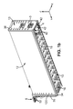
- the figures 1a and 1b represent a rolling lock gate 1 according to the invention.
- Said door comprises a rigid structure of parallelepipedal general shape, and has a first main face 11 and a second main face 12, these two main faces 11,12 being opposite and substantially parallel to each other.
- the rolling lock gate 1 according to the invention comprises an upper face 15, a lower face 10, a front end face 13 and a rear end face 14.
- Said lower faces 10, main 11.12 , front end 13, rear end 14, and upper 15 together define an interior door space 16.
- this interior door space 16 is preferably provided with multiple reinforcements and reinforcements 18 arranged in lattice, as illustrated in FIG. figure 1b .
- the axes of the Cartesian coordinate system are defined as follows: the Z axis is vertical and oriented upwards, the Y axis is parallel to the largest dimension (length) of the door, and the X axis is perpendicular to the two main faces 11,12.
- the rolling lock gate 1 contains in its lower part an access cavity 3, open downwards.
- This access cavity may preferably, as shown in FIG. figure 1b extend over a greater part of the length of the lower face, thus taking the general shape of a tunnel, notwithstanding the presence of lower reinforcements 18.
- the rolling lock gate 1 also contains a first sealing device 31, 32, 33 having a generally U-shaped shape open upwards, situated along the edges of the first main face 11, having a horizontal bottom portion 31, a front vertical portion 33 and a vertical portion rear 32.
- the rolling lock gate 1 according to the invention may also contain a second sealing device 34,35,36, also having a general shape of 'U' open upwards, located along edges of the second main face 12, having a horizontal lower portion 34, a front vertical portion 36 and a rearward vertical portion 35.
- first and second sealing devices 31 to 36 are preferably, but not exclusively made of wood, and have a rectangular section for example.
- the rolling lock gate 1 may also contain an inflatable seal 6, also having an overall shape of 'U' open upwards, located on the edges of the first main face 11
- the inflatable seal 6 is adjacent to the first seal 31,32,33 throughout the length thereof, and its dimensions along the Y and Z axes are slightly smaller than the dimensions of the first seal 31,32,33 along the Y and Z axes, so that the 'U' traveled by the inflatable seal fits just inside the 'U' that runs through the first seal 31,32 33.
- the inflatable seal 6 comprises a rigid portion fixed to the first main face, and a flexible portion, made for example based on rubber or flexible plastic.
- the rolling lock gate 1 moves by rolling along the Y axis by means of two rolling devices, a lower rolling device 4 and an upper rolling device 5.
- the lower rolling device 4 is provided with at least one first wheel 42 rolling on at least one lower rail 41 and the upper rolling device 5 is provided with at least one second wheel 52 rolling on at least one upper rail 51.
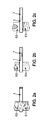
- the Figures 2a, 2b and 2c schematically illustrate certain configurations of a lock comprising a rolling lock gate 1 according to the invention, in particular in relation to a first space 81 which can be filled with liquid and with a second space 82 which can also be filled with liquid, the liquid in question being generally water, for example seawater or fresh water.
- the first space 81 is a stretch of water subject to a variable level, in this case it may be the sea or the ocean
- the second space 82 is a stretch of water having certain limits, such as a pool or an airlock.
- the rolling lock gate 1 is located in its withdrawal housing 7, and the two liquid spaces 81 and 82 are in direct communication, thus providing a free passage for ships that can pass from the first space 81 to the second space 82 , or conversely from the second to the first space.
- the lock gate is in a position called 'open'.
- the sluice gate is in a position called 'closed' in which it separates the two liquid spaces 81,82 from one another.
- the first liquid space 81 is subjected to a variable level, and is no longer in liquid communication with the second liquid space 82 which itself is subjected to a controlled level.
- the level of this second liquid space 82 can be kept constant in the case of a pond afloat, or even lowered or raised in the case of an airlock between two reaches as desired by the users of the lock. Since the means for controlling the level of the second liquid space 82 are known in the art, they will not be described in detail.
- the Figure 2c shows a particular use of a lock gate according to the invention.
- the second liquid space 82 is emptied of its liquid and hosts a construction site or ship repair.
- the second space thus dried makes it possible to build or to repair a ship, operation which can last a significant time like several months or years.
- the ship is simply returned to the water by allowing water to enter the second space 82 and then, when the liquid level of the second space 82 has reached the first space 81 level, it proceeds to the opening of the lock gate by moving to its recess housing 7, and the ship can thus join the first space 81, that is to say, to go to sea.
- the Figures 4a and 4b respectively present a section of the lock masonry alone, prior to the installation of the lock gate.
- the recess housing 7 of the door has a first wall 71, a bottom 72 and a second wall 73.
- the masonry of the lock comprises a first span 61,62,63 comprising a lower portion 61, a vertical portion before 63 and a rear vertical portion 62.
- the masonry of the lock comprises, where appropriate, a second span 64, 65, 66 comprising a lower portion 64, a vertical portion before 66 and a rear vertical portion 65.
- the masonry of the lock may include an auxiliary bearing 67,68,69 including a horizontal portion 67, a front vertical portion 69 and a rear vertical portion 68.
- the masonry comprises a raceway 2, located between said lower portions 61,64 of said first and second surfaces belonging to the masonry, for receiving at least one rail 41 on which rolls the lower rolling device 4 of the door of lock.
- This raceway 2 preferably comprises at least one other rail 41, and the rolling device 4 comprises at least one wheel 42, preferably two wheels 42 or four wheels 42 as shown in FIG. figure 1b .
- FIG 4a On the figure 4a is also visible at least one upper rail 51 located in the upper part of the wall 73 of the withdrawal housing. Furthermore, it is preferably a second upper rail 51 located in the upper part of the wall 71 of the withdrawal housing is visible on the figure 4b .
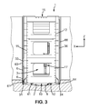
- the figure 3 shows a section of the rolling lock gate according to the invention, along the section line III of the figure 1a .
- the upper face 15 On the section are illustrated the upper face 15, the first main face 11 and the second main face 12, as well as the lower face 10.
- the front vertical portion 33 of the first sealing device is located vis-à-vis the vertical front portion 63 of the first span of the lock masonry.
- the lower portion 31 of the first sealing device is located vis-à-vis the lower portion 61 of the first range of the lock masonry.
- the vertical front portion 36 of the second sealing device is located opposite the vertical front portion 66 of the second span of the lock masonry.
- the lower portion 34 of the second sealing device is located vis-à-vis the lower portion 64 of the second range of the lock masonry.
- the horizontal and vertical portions 34,36 of the second sealing device are separated from the lower and vertical portions 64,66 of the second span of the lock masonry by a second functional clearance, which is substantially identical to the first one. functional play in the absence of forces exerted on the door 1 according to the direction X.
- the spacing between the rear vertical portions 62,65 respectively of the first and second span of the lock masonry is less than the corresponding gap between the vertical portions before 63,66 respectively of the first and second lands of the lock masonry, to allow a complete removal of the door 1 in the housing of withdrawal as this is represented on the Figures 2a .
- the figure 5 highlights the upper rolling device 5, provided with wheels 52, able to roll on the rails 51.
- the rear end of the lower rails 41 of the raceway 2 is visible.
- the figure 6 is a schematic sectional view, parallel to the YZ plane, along the line VI of the figure 5 , where it can be seen that the second sealing device 34,35,36, is in the form of a 'U' open top and of the same shape as the 'U' formed by the second masonry surface 64,65 , 66, so as to be able to press against each other continuously over the entire length of this U-shape, thereby providing the desired seal.
- the section also shows a portion 120 of the edge of the second main face, visible because the rear vertical portion 35 is projecting relative to the other portions of the second sealing device, and is somewhat offset to the X negative.
- the upper rail 51 is located in the upper part of the wall 73 of the door recess housing.
- the figure 7 is a partial top view of the front end of the rolling lock gate when the latter is pressed by the pressure (this pressure may be a liquid pressure P or a pressure generated by mechanical or hydraulic means) in the direction of the first range of masonry (towards positive X's).
- this pressure may be a liquid pressure P or a pressure generated by mechanical or hydraulic means
- the door is shifted from its neutral position in the X direction and its first main face 11 abuts on the first range of the masonry 61,62,63.
- This has the effect of sealingly isolating the first space 81 relative to the internal space 16 of the lock gate, the raceway 2 and the second space 82.
- the horizontal portion 31 before the first sealing device is pressed against the lower portion 61 of the first span of the lock masonry.
- the front and rear vertical portions 33, 32 of the first sealing device are respectively pressed against the front and rear vertical portions 63,62 of the first span of the lock masonry.
- the first main face 11 has a continuous surface inside the surface delimited by the 'U' formed by the first sealing device, so the water can not pass through the first main face 11.
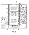
- the figure 8 is a sectional elevation of the rolling lock gate according to the invention, in the configuration shown in Fig 7 previously described.
- the door being pressed on its first main face 11 by the pressure P prevailing in the second space 82, greater than the pressure prevailing in the first space 81, the first sealing device 31,32,33 is pressed against the first bearing 61 , 62.63 of the lock masonry, thus providing a tight separation between the space 81 and the internal space 16 of the door 1.
- the second sealing device 34,35,36 being away from the second range of the masonry 64,65,66, and the functional clearance 26 passes water from the second space 82, this water filling the internal space 16 of the door, including the access cavity 3 in the lower part, and also the raceway 2.
- the water level inside the door is at the same level as the water in the second space 82.
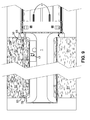
- the figure 9 is a view similar to the figure 5 , the door being pressed on its first main face 11 by pressure, with an auxiliary sealing device 37,38,39 in position.
- This auxiliary sealing device comprises a lower part 37, a rear vertical part 38, and a front vertical part 39 (which are also illustrated on FIG. figure 10 ).
- the lower portion 37 bears on the horizontal portion 67 of the auxiliary span of the lock masonry, the rear vertical portion 38 on the rear vertical portion 68 of the auxiliary span of the lock masonry, and the vertical front portion 39 door to the front vertical portion 69 of the auxiliary span of the lock masonry.
- These auxiliary sealing elements 37, 38, 39 cooperate with the portions 67, 68, 69 of the auxiliary surface of the masonry to seal the raceway 2 and the interior space 16 of the door 1 with respect to the second space 82.
- the recess housing 7, the internal space 16 of the door 1 and the access cavity 3 are sealingly insulated from the two bodies of water 81,82. This area can then be dewatered.
- a pumping device 19 (not detailed because known in the state of the art) is used: the water is taken from the withdrawal housing 7 until dry, as well as the access cavity 3 which is in fluid communication with said withdrawal housing 7.
- the access cavity 3 After the access cavity 3 has been emptied and dried, it is possible for a human to descend into said access cavity 3, taking a passage 17 provided for this purpose, located in the internal space 16 of the door 1, and which extends from the upper face 15 until to the access cavity 3, and comprising for example one or more stairs 17.
- the access cavity 3 being open downwards, the human intervener or workers can inspect the raceway 2, the or rails 41, which the rest of the time are inaccessible because immersed.
- the lower element 37 of the auxiliary sealing device can be mounted movably on the second main face 12 of the rolling door, for example pivoting about a horizontal axis of rotation 370.
- the lower member 37 is in the retracted position, raised against the second main face 12, parallel to it.
- the lower member 37 is in the active position, that is to say on the horizontal auxiliary bearing surface 67 of the masonry.
- the lower element 37 can be easily operated between the retracted position and the active position, and vice versa, and a difficult handling operation is avoided to bring the lower element 37 down to the bottom of the lock.
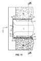
- the figure 11 is a partial view from above of the front end of the rolling lock gate 1, in a configuration different from the previous ones, the door being pressed this time on its second main face 12 by the pressure P which reigns in the first space 81 , greater than the pressure that reigns in space 82.
- the door is shifted from its neutral position in the direction of the negative X and its second main face 12 abuts on the second range of the masonry 64,65,66.
- This has the effect of sealingly isolating the second space 82 relative to the internal space 16 of the lock gate, the raceway 2 and at the first space 81.
- the horizontal portion 34 of the second sealing device is pressed against the lower portion 64 of the second range of the lock masonry.
- the front and rear vertical portions 36, 35 of the second sealing device are respectively pressed against the front and rear vertical portions 66, 65 of the second span of the lock masonry.
- the second main face 12 has a continuous surface inside the surface delimited by the 'U' formed by the second sealing device, so the water can not not pass through the second main face 12.
- the liquid level in the space 82 can be controlled by hydraulic means.
- the level can be lowered until this second space 82 is completely emptied. Indeed, if we want to build or repair a dry ship, we proceed to the drying of the second space 82 (as illustrated on the Figure 2c .
- the first sealing device 31, 32, 33 being remote from the first span of the masonry 61, 62,63, the water of the first space 81 can thus enter through this clearance in the interior space 16 of the door.
- the figure 12 is a sectional elevation of the rolling lock gate, the door being pressed against its second main face 12 by the pressure of the first space 81, and the second space having been dried as has been described in connection with the figure 11 .
- the lock gate remains pressed against the second masonry 64,65,66.
- a ship building site can last several months, and thus the lock gate will remain stationary in the position of the figure 12 all the time that will last the construction of the ship.
- the figure 12 also shows a lower cavity 8, bounded downwards by the race 2, upwards by the lower face 10 of the door 1, and on the sides by the lower portions 61,64 of the first and second spans of FIG. lock masonry. It is generally in this cavity that detritus and / or mud accumulate, which are then deposited on the raceway 2.
- the invention proposes the use of the inflatable seal 6, which can be inflated or deflated, and whose operation will be described below.
- the figure 13 is a view similar to figures 5 and 9 , the door being pressed this time on its second main face 12 by pressure.
- the inflatable seal 6 is in the state of rest, that is to say not inflated; on the other hand in the case illustrated on the figure 13 (and also on figures 14 and 16b ) the inflatable seal 6 is in the inflated position.
- the inflatable seal 6 extends in a direction opposite to the first main face 11, and over the entire length of the inflatable seal 6, it comes to bear on the first masonry bearing 61,62, 63.
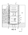
- the figure 14 is a view similar to the figure 12 , in which the inflatable seal is inflated, identical configuration to that just described for the figure 13 .
- the internal space 16 of the door 1, including the access cavity 3 located in the lower part, remain filled with water, but without communication with the first space 81.
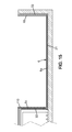
- the figure 15 is a schematic sectional view, parallel to the YZ plane, along line XV of the figure 13 , where it can be seen that the inflatable seal 6 extends continuously along the first masonry span by traversing a 'U' shape, and comprising a lower portion 6a, a front vertical portion 6b and a portion vertical rear 6c, so as to be pressed against the 'U' formed by the first masonry 61,32,63 range.
- the inflatable seal 6 is made in one piece, the lower part 6a being connected in continuity with the front vertical portion 6b respectively and with the rear vertical portion 6c.
- the first sealing device 31, 32, 33 is also in the form of a 'U' open top and of the same shape as the 'U' formed by the first masonry span 61, 32, 63 so as to be able to press one against the other in a continuous manner on any the length of this shape in 'U', thus providing the desired seal.
- the section also shows a portion 110 of the edge of the first main face, visible because the rear vertical portion 32 is projecting relative to the other portions of the first sealing device, and is somewhat offset to the X positive.
- FIGs 16a and 16b are detailed views showing a section of the inflatable seal 6, respectively in the deflated state ( figure 16a ), and inflated ( figure 16b ).
- the profile of the inflatable seal 6 comprises a base 94 parallel to the first main face 11, first and second lateral flanges 92, 93, extending perpendicularly to said base 94, and a flexible membrane portion 90, 91 which moves between a retracted position 90 if the inflatable seal 6 is deflated and a protruding position 91 if the inflatable seal 6 is inflated.
- the flexible membrane portion In the deflated state, the flexible membrane portion does not exceed the thickness defined by the lower portion of the first sealing device 31, whereas in the inflated state, the flexible membrane portion protrudes and bears against the lower portion 61 of the first masonry span, thus canceling the clearance 23 created by the fact that the door is pressed against the second masonry span.
- the sectional profile of the inflatable seal 6 which has just been described extends continuously over the entire length of said inflatable seal 6, thus defining an interior space 95 which extends all along the 'U' formed by the seal 6. Therefore, it is sufficient to connect this space 95 to an inflation device (not shown) for example at the upper end of the rear vertical portion 6c of the inflatable seal 6, so that it is it is possible to simultaneously inflate the assembly of the inflatable seal 6, or conversely to deflate it simultaneously.
- the inflatable seal 6 is equipped with a pressure sensor 96 which makes it possible to control the pressure prevailing in the inner space 95 of the inflatable seal 6, in particular so as to detect a potential leak.
- a second inflatable seal similar to the first, can be mounted on the second main face 12 of the door, with a geometry symmetrical with respect to the YZ plane.
- This second inflatable seal, mounted on the second main face 12, may be a complementary solution of the auxiliary sealing device 37,38,39 or even replace this same auxiliary sealing device 37,38,39 to avoid maneuvers to set up the latter.
Landscapes
- Engineering & Computer Science (AREA)
- Structural Engineering (AREA)
- General Engineering & Computer Science (AREA)
- Mechanical Engineering (AREA)
- Civil Engineering (AREA)
- Barrages (AREA)
- Specific Sealing Or Ventilating Devices For Doors And Windows (AREA)
- Special Wing (AREA)
Priority Applications (1)
| Application Number | Priority Date | Filing Date | Title |
|---|---|---|---|
| PL09168794T PL2159331T3 (pl) | 2008-09-02 | 2009-08-27 | Śluza z przesuwnymi wrotami |
Applications Claiming Priority (1)
| Application Number | Priority Date | Filing Date | Title |
|---|---|---|---|
| FR0855877A FR2935405B1 (fr) | 2008-09-02 | 2008-09-02 | Porte d'ecluse roulante avec joint gonflable et ecluse comprenant une telle porte |
Publications (2)
| Publication Number | Publication Date |
|---|---|
| EP2159331A1 true EP2159331A1 (de) | 2010-03-03 |
| EP2159331B1 EP2159331B1 (de) | 2013-08-14 |
Family
ID=40473515
Family Applications (1)
| Application Number | Title | Priority Date | Filing Date |
|---|---|---|---|
| EP09168794.7A Active EP2159331B1 (de) | 2008-09-02 | 2009-08-27 | Schleuse mit einem Rolltor |
Country Status (5)
| Country | Link |
|---|---|
| EP (1) | EP2159331B1 (de) |
| ES (1) | ES2431348T3 (de) |
| FR (1) | FR2935405B1 (de) |
| PL (1) | PL2159331T3 (de) |
| PT (1) | PT2159331E (de) |
Cited By (1)
| Publication number | Priority date | Publication date | Assignee | Title |
|---|---|---|---|---|
| CN111501686A (zh) * | 2019-01-30 | 2020-08-07 | 三久建材工业股份有限公司 | 油压旋摆式防水闸门控制装置 |
Citations (3)
| Publication number | Priority date | Publication date | Assignee | Title |
|---|---|---|---|---|
| FR1487282A (fr) * | 1966-07-22 | 1967-06-30 | C E Bell | Dispositif d'étanchéité pour une porte ou une paroi de retenue de fluide |
| DE3916558A1 (de) | 1989-01-20 | 1990-07-26 | Gewerk Eisenhuette Westfalia | Einrichtung zur absperrung einer wandoeffnung in schottwaenden, schutzdaemmen u. dgl. |
| EP1462574A2 (de) * | 2003-03-28 | 2004-09-29 | Horst Schmidt | Vorrichtung und Verfahren zum Abdichten einer Durchlassöffnung |
-
2008
- 2008-09-02 FR FR0855877A patent/FR2935405B1/fr active Active
-
2009
- 2009-08-27 PL PL09168794T patent/PL2159331T3/pl unknown
- 2009-08-27 ES ES09168794T patent/ES2431348T3/es active Active
- 2009-08-27 EP EP09168794.7A patent/EP2159331B1/de active Active
- 2009-08-27 PT PT91687947T patent/PT2159331E/pt unknown
Patent Citations (3)
| Publication number | Priority date | Publication date | Assignee | Title |
|---|---|---|---|---|
| FR1487282A (fr) * | 1966-07-22 | 1967-06-30 | C E Bell | Dispositif d'étanchéité pour une porte ou une paroi de retenue de fluide |
| DE3916558A1 (de) | 1989-01-20 | 1990-07-26 | Gewerk Eisenhuette Westfalia | Einrichtung zur absperrung einer wandoeffnung in schottwaenden, schutzdaemmen u. dgl. |
| EP1462574A2 (de) * | 2003-03-28 | 2004-09-29 | Horst Schmidt | Vorrichtung und Verfahren zum Abdichten einer Durchlassöffnung |
Cited By (1)
| Publication number | Priority date | Publication date | Assignee | Title |
|---|---|---|---|---|
| CN111501686A (zh) * | 2019-01-30 | 2020-08-07 | 三久建材工业股份有限公司 | 油压旋摆式防水闸门控制装置 |
Also Published As
| Publication number | Publication date |
|---|---|
| PT2159331E (pt) | 2013-10-21 |
| ES2431348T3 (es) | 2013-11-26 |
| FR2935405A1 (fr) | 2010-03-05 |
| PL2159331T3 (pl) | 2014-03-31 |
| FR2935405B1 (fr) | 2013-09-27 |
| EP2159331B1 (de) | 2013-08-14 |
Similar Documents
| Publication | Publication Date | Title |
|---|---|---|
| EP2159330B1 (de) | Schleusenrolltor und Schleuse mit einem derartigen Schleusentor | |
| CA2731070C (fr) | Support flottant comprenant un touret equipe de deux bouees d'amarrage de lignes d'ancrage et de conduites de liaison fond/surface | |
| EP1246991A1 (de) | Anpassbares abdichtsystem gegen hochwasser | |
| FR2976891A1 (fr) | Voiture de vehicule ferroviaire comprenant un systeme d'acces pour combler la lacune entre un nez de quai ferroviaire et un plancher de la voiture. | |
| FR2842234A1 (fr) | Barriere de protection escamotable disposee en peripherie du bassin d'une piscine | |
| EP2159331B1 (de) | Schleuse mit einem Rolltor | |
| WO2001086102A1 (fr) | Systeme d'etancheite contre toutes rentrees d'eau dans une construction | |
| FR2813624A1 (fr) | Profile de raccord et d'etancheite, dispositif de raccord, panneau a structure sandwich, et ensemble de facade, de cloison ou de couverture | |
| FR2981389A1 (fr) | Accessoire de type buse, destine a equiper un profile de menuiserie, pour l'ecoulement de l'eau susceptible de s'accumuler dans une chambre dudit profile | |
| EP1578661A1 (de) | Anlage zur gewinnung eines in mindestens einem querabschnitt dertanks eines gesunkenen schiffs enthaltenden verunreinigungsfluids | |
| EP0688904B1 (de) | Schleusentor | |
| EP2196601A1 (de) | Befestigungsvorrichtung für einen Tauchmotor in einem Schwimmbecken zum Antrieb von Rollos | |
| FR3091889A1 (fr) | Elément rigide pour un système de couverture de piscine | |
| CA2578034C (fr) | Porte de vehicule equipee d'un joint | |
| FR2896313A1 (fr) | Procede et dispositif pour detecter des fuites entre deux parois consecutives d'un bassin contenant un fluide | |
| EP1957717B1 (de) | Hafenstruktur und verfahren zum aufbau einer solchen struktur | |
| FR2785014A1 (fr) | Dispositif d'obturation d'une ouverture menagee dans un mur, en particulier, pour la lutte contre les inondations | |
| FR3106842A1 (fr) | Structure de rangement et de protection d’un volet roulant adapté pour recouvrir un bassin tout en intégrant une plage immergée | |
| FR3017647A1 (fr) | Caisson pour un moyen roulant d'occultation | |
| FR3103459A1 (fr) | Fenêtre vitrée pour navire équipée d’une ouverture se fermant à l’aide d’un panneau vitré basculant. | |
| EP0957228A1 (de) | Dichte Schiebetüreinrichtung, insbesondere für einen Raum mit geregelter Atmosphäre, wie ein Labor | |
| EP4520895A1 (de) | Becken, wie ein schwimmbecken, mit einer versenkten abdeckung vom typ rolladen | |
| FR3018529A1 (fr) | Abri telescopique, notamment pour une terrasse | |
| EP2960400B1 (de) | Aufrollbare Abdeckung für ein Schwimmbecken | |
| FR2720767A1 (fr) | Bateaux-portes. |
Legal Events
| Date | Code | Title | Description |
|---|---|---|---|
| PUAI | Public reference made under article 153(3) epc to a published international application that has entered the european phase |
Free format text: ORIGINAL CODE: 0009012 |
|
| AK | Designated contracting states |
Kind code of ref document: A1 Designated state(s): AT BE BG CH CY CZ DE DK EE ES FI FR GB GR HR HU IE IS IT LI LT LU LV MC MK MT NL NO PL PT RO SE SI SK SM TR |
|
| 17P | Request for examination filed |
Effective date: 20100827 |
|
| 17Q | First examination report despatched |
Effective date: 20101208 |
|
| RAP1 | Party data changed (applicant data changed or rights of an application transferred) |
Owner name: EIFFAGE CONSTRUCTION METALLIQUE |
|
| GRAP | Despatch of communication of intention to grant a patent |
Free format text: ORIGINAL CODE: EPIDOSNIGR1 |
|
| GRAS | Grant fee paid |
Free format text: ORIGINAL CODE: EPIDOSNIGR3 |
|
| GRAA | (expected) grant |
Free format text: ORIGINAL CODE: 0009210 |
|
| AK | Designated contracting states |
Kind code of ref document: B1 Designated state(s): AT BE BG CH CY CZ DE DK EE ES FI FR GB GR HR HU IE IS IT LI LT LU LV MC MK MT NL NO PL PT RO SE SI SK SM TR |
|
| REG | Reference to a national code |
Ref country code: GB Ref legal event code: FG4D Free format text: NOT ENGLISH |
|
| REG | Reference to a national code |
Ref country code: CH Ref legal event code: EP Ref country code: AT Ref legal event code: REF Ref document number: 626971 Country of ref document: AT Kind code of ref document: T Effective date: 20130815 |
|
| REG | Reference to a national code |
Ref country code: IE Ref legal event code: FG4D Free format text: LANGUAGE OF EP DOCUMENT: FRENCH |
|
| REG | Reference to a national code |
Ref country code: DE Ref legal event code: R096 Ref document number: 602009017932 Country of ref document: DE Effective date: 20131010 |
|
| REG | Reference to a national code |
Ref country code: PT Ref legal event code: SC4A Free format text: AVAILABILITY OF NATIONAL TRANSLATION Effective date: 20131014 |
|
| REG | Reference to a national code |
Ref country code: NL Ref legal event code: T3 |
|
| REG | Reference to a national code |
Ref country code: ES Ref legal event code: FG2A Ref document number: 2431348 Country of ref document: ES Kind code of ref document: T3 Effective date: 20131126 |
|
| REG | Reference to a national code |
Ref country code: AT Ref legal event code: MK05 Ref document number: 626971 Country of ref document: AT Kind code of ref document: T Effective date: 20130814 |
|
| REG | Reference to a national code |
Ref country code: LT Ref legal event code: MG4D |
|
| PG25 | Lapsed in a contracting state [announced via postgrant information from national office to epo] |
Ref country code: SE Free format text: LAPSE BECAUSE OF FAILURE TO SUBMIT A TRANSLATION OF THE DESCRIPTION OR TO PAY THE FEE WITHIN THE PRESCRIBED TIME-LIMIT Effective date: 20130814 Ref country code: NO Free format text: LAPSE BECAUSE OF FAILURE TO SUBMIT A TRANSLATION OF THE DESCRIPTION OR TO PAY THE FEE WITHIN THE PRESCRIBED TIME-LIMIT Effective date: 20131114 Ref country code: CY Free format text: LAPSE BECAUSE OF FAILURE TO SUBMIT A TRANSLATION OF THE DESCRIPTION OR TO PAY THE FEE WITHIN THE PRESCRIBED TIME-LIMIT Effective date: 20130821 Ref country code: IS Free format text: LAPSE BECAUSE OF FAILURE TO SUBMIT A TRANSLATION OF THE DESCRIPTION OR TO PAY THE FEE WITHIN THE PRESCRIBED TIME-LIMIT Effective date: 20131214 Ref country code: HR Free format text: LAPSE BECAUSE OF FAILURE TO SUBMIT A TRANSLATION OF THE DESCRIPTION OR TO PAY THE FEE WITHIN THE PRESCRIBED TIME-LIMIT Effective date: 20130814 Ref country code: AT Free format text: LAPSE BECAUSE OF FAILURE TO SUBMIT A TRANSLATION OF THE DESCRIPTION OR TO PAY THE FEE WITHIN THE PRESCRIBED TIME-LIMIT Effective date: 20130814 Ref country code: LT Free format text: LAPSE BECAUSE OF FAILURE TO SUBMIT A TRANSLATION OF THE DESCRIPTION OR TO PAY THE FEE WITHIN THE PRESCRIBED TIME-LIMIT Effective date: 20130814 |
|
| PG25 | Lapsed in a contracting state [announced via postgrant information from national office to epo] |
Ref country code: FI Free format text: LAPSE BECAUSE OF FAILURE TO SUBMIT A TRANSLATION OF THE DESCRIPTION OR TO PAY THE FEE WITHIN THE PRESCRIBED TIME-LIMIT Effective date: 20130814 Ref country code: GR Free format text: LAPSE BECAUSE OF FAILURE TO SUBMIT A TRANSLATION OF THE DESCRIPTION OR TO PAY THE FEE WITHIN THE PRESCRIBED TIME-LIMIT Effective date: 20131115 Ref country code: LV Free format text: LAPSE BECAUSE OF FAILURE TO SUBMIT A TRANSLATION OF THE DESCRIPTION OR TO PAY THE FEE WITHIN THE PRESCRIBED TIME-LIMIT Effective date: 20130814 Ref country code: SI Free format text: LAPSE BECAUSE OF FAILURE TO SUBMIT A TRANSLATION OF THE DESCRIPTION OR TO PAY THE FEE WITHIN THE PRESCRIBED TIME-LIMIT Effective date: 20130814 |
|
| PG25 | Lapsed in a contracting state [announced via postgrant information from national office to epo] |
Ref country code: CY Free format text: LAPSE BECAUSE OF FAILURE TO SUBMIT A TRANSLATION OF THE DESCRIPTION OR TO PAY THE FEE WITHIN THE PRESCRIBED TIME-LIMIT Effective date: 20130814 |
|
| REG | Reference to a national code |
Ref country code: CH Ref legal event code: PL |
|
| PG25 | Lapsed in a contracting state [announced via postgrant information from national office to epo] |
Ref country code: RO Free format text: LAPSE BECAUSE OF FAILURE TO SUBMIT A TRANSLATION OF THE DESCRIPTION OR TO PAY THE FEE WITHIN THE PRESCRIBED TIME-LIMIT Effective date: 20130814 Ref country code: EE Free format text: LAPSE BECAUSE OF FAILURE TO SUBMIT A TRANSLATION OF THE DESCRIPTION OR TO PAY THE FEE WITHIN THE PRESCRIBED TIME-LIMIT Effective date: 20130814 Ref country code: CH Free format text: LAPSE BECAUSE OF NON-PAYMENT OF DUE FEES Effective date: 20130831 Ref country code: CZ Free format text: LAPSE BECAUSE OF FAILURE TO SUBMIT A TRANSLATION OF THE DESCRIPTION OR TO PAY THE FEE WITHIN THE PRESCRIBED TIME-LIMIT Effective date: 20130814 Ref country code: LI Free format text: LAPSE BECAUSE OF NON-PAYMENT OF DUE FEES Effective date: 20130831 Ref country code: SK Free format text: LAPSE BECAUSE OF FAILURE TO SUBMIT A TRANSLATION OF THE DESCRIPTION OR TO PAY THE FEE WITHIN THE PRESCRIBED TIME-LIMIT Effective date: 20130814 Ref country code: DK Free format text: LAPSE BECAUSE OF FAILURE TO SUBMIT A TRANSLATION OF THE DESCRIPTION OR TO PAY THE FEE WITHIN THE PRESCRIBED TIME-LIMIT Effective date: 20130814 |
|
| PG25 | Lapsed in a contracting state [announced via postgrant information from national office to epo] |
Ref country code: MC Free format text: LAPSE BECAUSE OF FAILURE TO SUBMIT A TRANSLATION OF THE DESCRIPTION OR TO PAY THE FEE WITHIN THE PRESCRIBED TIME-LIMIT Effective date: 20130814 Ref country code: IT Free format text: LAPSE BECAUSE OF FAILURE TO SUBMIT A TRANSLATION OF THE DESCRIPTION OR TO PAY THE FEE WITHIN THE PRESCRIBED TIME-LIMIT Effective date: 20130814 |
|
| PLBE | No opposition filed within time limit |
Free format text: ORIGINAL CODE: 0009261 |
|
| STAA | Information on the status of an ep patent application or granted ep patent |
Free format text: STATUS: NO OPPOSITION FILED WITHIN TIME LIMIT |
|
| 26N | No opposition filed |
Effective date: 20140515 |
|
| REG | Reference to a national code |
Ref country code: DE Ref legal event code: R097 Ref document number: 602009017932 Country of ref document: DE Effective date: 20140515 |
|
| PG25 | Lapsed in a contracting state [announced via postgrant information from national office to epo] |
Ref country code: SM Free format text: LAPSE BECAUSE OF FAILURE TO SUBMIT A TRANSLATION OF THE DESCRIPTION OR TO PAY THE FEE WITHIN THE PRESCRIBED TIME-LIMIT Effective date: 20130814 |
|
| PG25 | Lapsed in a contracting state [announced via postgrant information from national office to epo] |
Ref country code: MT Free format text: LAPSE BECAUSE OF FAILURE TO SUBMIT A TRANSLATION OF THE DESCRIPTION OR TO PAY THE FEE WITHIN THE PRESCRIBED TIME-LIMIT Effective date: 20130814 Ref country code: TR Free format text: LAPSE BECAUSE OF FAILURE TO SUBMIT A TRANSLATION OF THE DESCRIPTION OR TO PAY THE FEE WITHIN THE PRESCRIBED TIME-LIMIT Effective date: 20130814 |
|
| PG25 | Lapsed in a contracting state [announced via postgrant information from national office to epo] |
Ref country code: BG Free format text: LAPSE BECAUSE OF FAILURE TO SUBMIT A TRANSLATION OF THE DESCRIPTION OR TO PAY THE FEE WITHIN THE PRESCRIBED TIME-LIMIT Effective date: 20130814 Ref country code: HU Free format text: LAPSE BECAUSE OF FAILURE TO SUBMIT A TRANSLATION OF THE DESCRIPTION OR TO PAY THE FEE WITHIN THE PRESCRIBED TIME-LIMIT; INVALID AB INITIO Effective date: 20090827 Ref country code: LU Free format text: LAPSE BECAUSE OF NON-PAYMENT OF DUE FEES Effective date: 20130827 Ref country code: MK Free format text: LAPSE BECAUSE OF FAILURE TO SUBMIT A TRANSLATION OF THE DESCRIPTION OR TO PAY THE FEE WITHIN THE PRESCRIBED TIME-LIMIT Effective date: 20130814 |
|
| REG | Reference to a national code |
Ref country code: FR Ref legal event code: PLFP Year of fee payment: 7 |
|
| REG | Reference to a national code |
Ref country code: FR Ref legal event code: PLFP Year of fee payment: 8 |
|
| REG | Reference to a national code |
Ref country code: FR Ref legal event code: PLFP Year of fee payment: 9 |
|
| REG | Reference to a national code |
Ref country code: FR Ref legal event code: PLFP Year of fee payment: 10 |
|
| PGFP | Annual fee paid to national office [announced via postgrant information from national office to epo] |
Ref country code: NL Payment date: 20250724 Year of fee payment: 17 |
|
| PGFP | Annual fee paid to national office [announced via postgrant information from national office to epo] |
Ref country code: ES Payment date: 20250908 Year of fee payment: 17 Ref country code: PT Payment date: 20250718 Year of fee payment: 17 |
|
| PGFP | Annual fee paid to national office [announced via postgrant information from national office to epo] |
Ref country code: DE Payment date: 20250812 Year of fee payment: 17 |
|
| PGFP | Annual fee paid to national office [announced via postgrant information from national office to epo] |
Ref country code: PL Payment date: 20250722 Year of fee payment: 17 |
|
| PGFP | Annual fee paid to national office [announced via postgrant information from national office to epo] |
Ref country code: BE Payment date: 20250826 Year of fee payment: 17 Ref country code: GB Payment date: 20250826 Year of fee payment: 17 |
|
| PGFP | Annual fee paid to national office [announced via postgrant information from national office to epo] |
Ref country code: FR Payment date: 20250721 Year of fee payment: 17 |
|
| PGFP | Annual fee paid to national office [announced via postgrant information from national office to epo] |
Ref country code: IE Payment date: 20250728 Year of fee payment: 17 |