EP2159369A2 - Weihnachtsbaum mit intern positioniertem Durchflussmesser - Google Patents
Weihnachtsbaum mit intern positioniertem Durchflussmesser Download PDFInfo
- Publication number
- EP2159369A2 EP2159369A2 EP09176533A EP09176533A EP2159369A2 EP 2159369 A2 EP2159369 A2 EP 2159369A2 EP 09176533 A EP09176533 A EP 09176533A EP 09176533 A EP09176533 A EP 09176533A EP 2159369 A2 EP2159369 A2 EP 2159369A2
- Authority
- EP
- European Patent Office
- Prior art keywords
- gas
- production
- assembly
- gas separator
- flow
- Prior art date
- Legal status (The legal status is an assumption and is not a legal conclusion. Google has not performed a legal analysis and makes no representation as to the accuracy of the status listed.)
- Granted
Links
- 241000191291 Abies alba Species 0.000 title claims abstract description 14
- 238000005259 measurement Methods 0.000 claims abstract description 69
- 238000004519 manufacturing process Methods 0.000 claims description 82
- 239000012530 fluid Substances 0.000 claims description 23
- 238000004891 communication Methods 0.000 claims description 10
- 238000000034 method Methods 0.000 description 16
- 238000000926 separation method Methods 0.000 description 7
- POIUWJQBRNEFGX-XAMSXPGMSA-N cathelicidin Chemical compound C([C@@H](C(=O)N[C@@H](CCCNC(N)=N)C(=O)N[C@@H](CCCCN)C(=O)N[C@@H](CO)C(=O)N[C@@H](CCCCN)C(=O)N[C@@H](CCC(O)=O)C(=O)N[C@@H](CCCCN)C(=O)N[C@@H]([C@@H](C)CC)C(=O)NCC(=O)N[C@@H](CCCCN)C(=O)N[C@@H](CCC(O)=O)C(=O)N[C@@H](CC=1C=CC=CC=1)C(=O)N[C@@H](CCCCN)C(=O)N[C@@H](CCCNC(N)=N)C(=O)N[C@@H]([C@@H](C)CC)C(=O)N[C@@H](C(C)C)C(=O)N[C@@H](CCC(N)=O)C(=O)N[C@@H](CCCNC(N)=N)C(=O)N[C@@H]([C@@H](C)CC)C(=O)N[C@@H](CCCCN)C(=O)N[C@@H](CC(O)=O)C(=O)N[C@@H](CC=1C=CC=CC=1)C(=O)N[C@@H](CC(C)C)C(=O)N[C@@H](CCCNC(N)=N)C(=O)N[C@@H](CC(N)=O)C(=O)N[C@@H](CC(C)C)C(=O)N[C@@H](C(C)C)C(=O)N1[C@@H](CCC1)C(=O)N[C@@H](CCCNC(N)=N)C(=O)N[C@@H]([C@@H](C)O)C(=O)N[C@@H](CCC(O)=O)C(=O)N[C@@H](CO)C(O)=O)NC(=O)[C@H](CC=1C=CC=CC=1)NC(=O)[C@H](CC(O)=O)NC(=O)CNC(=O)[C@H](CC(C)C)NC(=O)[C@@H](N)CC(C)C)C1=CC=CC=C1 POIUWJQBRNEFGX-XAMSXPGMSA-N 0.000 description 5
- 241000282472 Canis lupus familiaris Species 0.000 description 4
- 238000010276 construction Methods 0.000 description 4
- 101000793686 Homo sapiens Azurocidin Proteins 0.000 description 3
- 238000011161 development Methods 0.000 description 2
- 239000007788 liquid Substances 0.000 description 2
- 239000000463 material Substances 0.000 description 2
- 238000012986 modification Methods 0.000 description 2
- 230000004048 modification Effects 0.000 description 2
- 230000035515 penetration Effects 0.000 description 2
- XLYOFNOQVPJJNP-UHFFFAOYSA-N water Substances O XLYOFNOQVPJJNP-UHFFFAOYSA-N 0.000 description 2
- 229910000975 Carbon steel Inorganic materials 0.000 description 1
- 230000003466 anti-cipated effect Effects 0.000 description 1
- 239000010962 carbon steel Substances 0.000 description 1
- 238000013461 design Methods 0.000 description 1
- -1 e.g. Substances 0.000 description 1
- 230000000694 effects Effects 0.000 description 1
- 238000009429 electrical wiring Methods 0.000 description 1
- 238000005516 engineering process Methods 0.000 description 1
- 238000012544 monitoring process Methods 0.000 description 1
- 230000000737 periodic effect Effects 0.000 description 1
- 238000011064 split stream procedure Methods 0.000 description 1
- 239000010935 stainless steel Substances 0.000 description 1
- 229910001220 stainless steel Inorganic materials 0.000 description 1
Images



Classifications
-
- E—FIXED CONSTRUCTIONS
- E21—EARTH OR ROCK DRILLING; MINING
- E21B—EARTH OR ROCK DRILLING; OBTAINING OIL, GAS, WATER, SOLUBLE OR MELTABLE MATERIALS OR A SLURRY OF MINERALS FROM WELLS
- E21B33/00—Sealing or packing boreholes or wells
- E21B33/02—Surface sealing or packing
- E21B33/03—Well heads; Setting-up thereof
-
- E—FIXED CONSTRUCTIONS
- E21—EARTH OR ROCK DRILLING; MINING
- E21B—EARTH OR ROCK DRILLING; OBTAINING OIL, GAS, WATER, SOLUBLE OR MELTABLE MATERIALS OR A SLURRY OF MINERALS FROM WELLS
- E21B34/00—Valve arrangements for boreholes or wells
- E21B34/02—Valve arrangements for boreholes or wells in well heads
- E21B34/04—Valve arrangements for boreholes or wells in well heads in underwater well heads
-
- E—FIXED CONSTRUCTIONS
- E21—EARTH OR ROCK DRILLING; MINING
- E21B—EARTH OR ROCK DRILLING; OBTAINING OIL, GAS, WATER, SOLUBLE OR MELTABLE MATERIALS OR A SLURRY OF MINERALS FROM WELLS
- E21B47/00—Survey of boreholes or wells
- E21B47/10—Locating fluid leaks, intrusions or movements
-
- E—FIXED CONSTRUCTIONS
- E21—EARTH OR ROCK DRILLING; MINING
- E21B—EARTH OR ROCK DRILLING; OBTAINING OIL, GAS, WATER, SOLUBLE OR MELTABLE MATERIALS OR A SLURRY OF MINERALS FROM WELLS
- E21B43/00—Methods or apparatus for obtaining oil, gas, water, soluble or meltable materials or a slurry of minerals from wells
- E21B43/34—Arrangements for separating materials produced by the well
- E21B43/38—Arrangements for separating materials produced by the well in the well
Definitions
- the present invention is generally related to the field of oil and gas production equipment, and, more particularly, to a Christmas tree with an internally positioned flowmeter.
- the produced fluid is often a combination of gas, oil and water.
- Production of oil and gas from a well normally involves the use of a series of inlet and outlet cutoff valves commonly referred to as a Christmas tree that is positioned above the wellhead. It is very important to be able to accurately meter the amount of oil and gas flowing from such wells.
- Multi-phase flowmeters have been developed that are able to measure the flow of each of the three phases - oil, gas and water - in a single production stream.
- such multi-phase flowmeters are typically less accurate when the volume percentage of gas, sometimes referred to as the "gas cut,” is too high, e.g., greater than 97% or so.
- One known solution to such a problem involves separating some of the gas from the production stream to thereby reduce the gas cut.
- the separated gas flow is then measured by a separate gas meter, while the remaining production stream is measured using a multi-phase flowmeter.
- the two split streams are again combined downstream of the meters for transportation to a storage or production facility. In such a situation, the production stream from the well is separated only for metering purposes.
- separate metering of the type just described is typically accomplished in one of two ways.
- One method involves routing the production flow from all of the wells to a single manifold. Thereafter, the combined flow from the manifold is then separated and metered as described above. This technique does not permit measurement of the production flow from each well independently.
- Another method involves the use of an independent gas separator and metering unit which can be moved from well to well.
- the production flow from a particular well is temporarily re-routed through the gas separator/metering unit to measure the flow. While this technique enables the production flow of each well to be independently monitored, the flow from multiple wells cannot be monitored independently at the same time. Moreover, this latter technique involves repeated relocation of the gas separator/metering unit from well to well.
- the present invention is directed to an apparatus and methods for solving, or at least reducing the effects of, some or all of the aforementioned problems.
- a measurement device which comprises a structure adapted to be removably coupled to a Christmas tree, a sleeve operatively coupled to the structure and a flowmeter positioned at least partially within the sleeve.
- a measurement device which comprises a tree cap adapted to be removably coupled to a Christmas tree, a sleeve operatively coupled to the tree cap and a flowmeter positioned at least partially within the sleeve, wherein the sleeve comprises a production fluid outlet opening formed in the sleeve in a position that is downstream of the flowmeter during normal operation of a well and a kill fluid inlet opening formed in the sleeve in a position that is downstream of the flowmeter during normal operation of a well.
- a system for measuring production flow from a well which comprises a gas separator assembly that is adapted to be positioned above a wellhead and receive production flow from the well, the gas separator assembly comprising a gas separator device that is adapted to separate at least a portion of gas from the production flow, a flow measurement assembly adapted to be positioned downstream of the gas separator assembly, the flow measurement assembly comprising a flow measurement device that is adapted to receive and measure production flow after it has passed through the gas separator assembly, and a piping spool comprising a gas flowmeter, the gas flowmeter adapted to receive and measure gas separated from the production flow by the gas separator device.
- a device for measuring production flow from a well which comprises a gas separator assembly, the gas separator assembly comprising a gas separator device that is adapted to separate at least a portion of gas from the production flow, a flow measurement assembly positioned downstream of the gas separator device, the flow measurement assembly comprising a flow measurement device that is adapted to receive and measure production flow after it has passed through the gas separator assembly, and a housing that is adapted to be releasably coupled to a tubing hanger in the well, the gas separator assembly and the flow measurement assembly being operatively coupled to the housing.
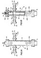
- FIGS. IA- IB depict an illustrative system 10 wherein one embodiment of the disclosed measuring system may be employed.
- a schematically depicted Christmas tree 14 is operatively coupled to a wellhead 12 such that production fluid from the well will flow through the Christmas tree 14.
- the subject matter disclosed herein may be employed with subsea or surface wells, and with any type of Christmas tree 14, e.g., horizontal or vertical.
- the term "Christmas tree" is believed to be well understood to those skilled in the art as a structure or body that comprises a plurality of valves used to control production from an oil or gas well.
- the Christmas tree 14 comprises a body 16, a cap 18 and a plurality of valves 20.
- the exact arrangement of the valves 20 may vary depending upon the particular application.
- the tree 14 comprises a lower master valve 20a, an upper master valve 20b, a swab valve 20c, a production wing valve 20d and a kill wing valve 20e.
- production flow from the well flows through the internal production passage 22 (see Figure IB) in the tree 14 and through the production wing valve 20d in the direction indicated by the arrow 24.
- a variety of fluids may be introduced through the kill wing valve 20e as indicated by the arrow 26.
- Such fluids may be introduced into the well for a variety of purposes, e.g., to kill the well.
- the tree 14 may be coupled to the wellhead 12 using a variety of known techniques, e.g., a clamped or bolted connection.
- additional components such as a tubing head and/or adapter, may be positioned between the tree 14 and the wellhead 12.
- a tubing head and/or adapter may be positioned between the tree 14 and the wellhead 12.
- Figures 1C and ID are, respectively, a cross-sectional view and a rear view of an illustrative measurement assembly 30 that generally comprises a sleeve 32 that is coupled to the tree cap 18, openings 34 and 36, a flow diverter or plug 40, and a measurement device 50.
- the opening 34 is adapted to be aligned with the production wing valve 20d
- the opening 36 is adapted to be aligned with the kill wing valve 20e.
- a bore 38 is provided in the tree cap 18 and a threaded electronics cap 37 is threadingly coupled to the tree cap 18.
- a seal 38a e.g., an O-ring type seal, is provided between the electronics cap 37 and the bore 38 to establish a pressure-tight seal.
- a plurality of seals 42 may be provided with the flow diverter 40 to substantially prevent the flow of production fluids above the plug 40.
- One or more seals 44 may also be provided to define a seal between the outside diameter of the sleeve 32 and the inside diameter of the production passage 22 of the tree 14. See Figure IB.
- the seals 44 are provided to prevent or limit the amount of production fluid that might bypass the measurement device 50.
- the seals 44 do not establish a pressure seal between the sleeve 32 and the inside diameter of the production passage 22 in the tree 14.
- the seals 42 adjacent the plug 40 do not establish a pressure-tight seal between the plug 40 and the inside diameter of the sleeve 32.
- a plurality of slots 53, 54 and 55 are formed, e.g., milled, into the backside of the sleeve 32.
- the slots 53, 54 and 55 are adapted to receive, for example, 0.25" tubing.
- Standard tubing fittings 51 may be employed to secure one end of the tubing to the measurement system 50.
- standard tubing fittings 41 are employed to sealingly couple the tubing to the electronics cap 37.
- the sleeve 32 is further provided with a plurality of openings 57 such that the tubing may be re-routed to the inside of the sleeve 32 above the flow diverter 40.
- three illustrative tubing lines are shown, although the number may vary depending on the particular application.
- the tubing may be used for a variety of purposes, e.g., as conduit for electrical wiring, for differential pressure readings, etc.
- the components depicted in Figures 1C and ID may be made from a variety of materials, e.g., stainless steel, carbon steel, etc.
- the thickness of the sleeve 32 will vary based on venturi geometric requirements governed by average flow rates and well bore pressure seen in a given well. In one example, the sleeve 32 may have a thickness of approximately 1/16-1 inch.
- the measurement device 50 may be comprised of any of a variety of known measurement utilities or devices, e.g., multiphase meters, vortex gas meters, separators, etc.
- the measurement device 50 may be secured within the sleeve 32 using a variety of known techniques, e.g., threaded connections, pin connections, snap rings, etc.
- the seals 42, 44 depicted herein may be made of any material sufficient to prevent or limit the bypass of production fluid under anticipated operating conditions.
- the measurement device 50 may be comprised of various internal components taken from any of a variety of different types of off-the-shelf measuring devices.
- the measurement assembly 30 is positioned in the production passage 22 of the tree 14. Thereafter, production flow from the well is directed out the opening 34 in the sleeve 32 and through the production wing valve 2Od in the direction indicated by the arrow 24. If desired, the measurement assembly 30 may be removed from the production passage 22 of the tree 14 by closing at least one of the valves 20a, 20b and decoupling the tree cap 18 from the tree 14. Thereafter, a traditional tree cap (not shown) may be coupled to the tree 14.
- the measurement device 50 measures the flow of the production fluid through the production passage 22 of the tree 14.
- each well may be provided with its own internally positioned measuring device to measure the flow from that well. The flow measurements can be made on a continuous or periodic basis.
- Figure 2A depicts an embodiment wherein a separator assembly 100 and a measurement assembly 130 are positioned between the wellhead 112 and the tree 150 in an in-line arrangement.
- the illustrative arrangement depicted in Figure 2A may vary depending upon the particular application.
- one or more additional components e.g., an adapter, a tubing head, etc.
- the various components depicted in Figure 2A may be operatively coupled to one another using any traditional techniques, e.g., bolts, clamps, etc.
- production tubing 113 through which production fluid from the well will flow.
- the separator device 106 may be comprised of internals from a CDS in-line separator or other types of separator devices.
- the separator assembly 100 comprises a body 102, a production passage 104, a separator device 106 positioned within the production passage 104, and a separated gas passage 108.
- the production passage 104 is substantially aligned with the production tubing 113.
- the separator device 106 may be any type of separator device whereby a portion of the gas in the production fluid may be separated and directed to the separated gas passage 108.
- the separator device may comprise one or more swirl elements that are adapted to cause the production fluid to swirl or rotate thereby tending to separate the gas and liquid in the production flow.
- the separator device 106 may be secured within the bore 104 using a variety of known techniques, e.g., landing a separation sleeve, with the entire separation device contained within, in a spool at the top of the tubing string.
- the flow measurement assembly 130 is operatively coupled to and positioned downstream of the separator assembly 100.
- the flow measurement assembly 130 comprises a production passage 134, a measurement device 136 positioned within the production passage 134, and a separated gas passage 138.
- the outlet 108a of the separated gas passage 108 in the separator assembly 100 is adapted to be operatively coupled to the inlet 138a of the separated gas passage 138 in the flow measurement assembly 130.
- the production passage 134 is substantially aligned with the production passage 104.
- the separated gas passage 138 positioned in the flow measurement assembly 130 is substantially aligned with the separated gas passage 108.
- the measurement device 106 may be any type of multi-phase flowmeter that is capable of accurately measuring the gas and/or liquid content of the production flow after some of the gas has been separated from the production flow by use of the separator device 106.
- the measurement device 136 may be secured within the production passage 134 using a variety of known techniques, e.g., landing on a shoulder designed into the measurement spool, etc.
- the tree 150 also comprises a production passage 154, a separated gas passage 158, a production wing valve 160 and a backup production wing valve 161.
- the outlet 138b of the separated gas passage 138 in the flow measurement assembly 130 is adapted to be operatively coupled to the inlet 158a of the separated gas passage 158 in the tree 150.
- the separated gas passage 158 in the tree 150 is in fluid communication with a pipe loop 151 that has a separated gas valve 155 and a gas meter 152 positioned therein.
- the gas meter 152 may be a traditional single phase type gas meter that is sufficient for measuring the quantity of gas flowing through the loop 151.
- the separated gas flowing through passage 158 flows outward through the separated gas valve 155 and through the gas meter 152, as indicated by arrows 163.
- the separated gas is recombined with the production fluid flowing through the production passages 134 and 154, and directed outward to the production flow line 156 through valve 161.
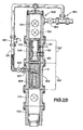
- Figure 2B depicts yet another illustrative embodiment of a separation assembly 100, a flow measurement assembly 130 and a tree 150.
- a tubing head 170 and tubing head adapter 171 are also schematically depicted in Figure 2B .
- the various components are provided by way of example only as the exact number and location of such components may vary depending on the application. Additionally, the various components depicted in Figure 2B may be coupled to one another using any of a variety of known techniques, e.g., clamps, bolts, etc.
- the separation assembly 100 comprises a gas separation device 106 and a gas outlet 107.
- the gas separation device 106 comprises a swirl element 109 and a gas collection device 111, e.g., a cone.
- the structure of such gas separation devices are well known to those skilled in the art.
- the flow measurement assembly 130 comprises a measurement device 136 which may be, for example, a multi-phase flowmeter.
- a plurality of penetrations 131 extend through the body 133 of the flow measurement assembly 130 to permit data from the measurement device 136 to be transmitted to a receiving device, such as a computer (not shown).
- the tree 150 comprises a lower master valve 190, an upper master valve 191 and a production wing valve 192 in accordance with traditional construction.
- the system depicted in Figure 2B further comprises a piping spool 151 having a gas meter 152 positioned therein.
- the gas meter 152 is adapted to measure the quantity of the separated gas from gas outlet 107 flowing through the piping spool 151 and provide such measurement data to a receiving device, e.g., a computer (not shown).
- the separated gas flowing through the loop 151 is ultimately recombined with the production flow through the tree 150 at point 194 downstream of the production wing valve 192.
- Figures 3A-3B depict yet another illustrative embodiment of a measurement device 300 that may be employed in oil and gas wells.
- the device 300 comprises a housing 333, an engageable electrical connector 334, an actuatable clamp or dog mechanism 335 and the previously described gas separator device 106 and measuring device 136.
- the various components depicted in Figure 3A may be coupled to one another using a variety of techniques.
- the measurement device 136 is threadingly coupled to the housing 333 and the gas separator device 106 is threadingly coupled to the measurement device 136 via an internally threaded collar 339.
- a plurality of electrical wires 340 extend from the measurement device 136 to the engageable electrical connector 334, e.g., a multi-pin connector.
- the gas separator device 106 further comprises a gas outlet opening 336, e.g., a ⁇ 1>A" diameter opening, and a plurality of pressure equalization openings 337a, 337b.
- the measurement device 136 also comprises a plurality of pressure equalization openings 338a, 338b, and openings 341a, 341b b for monitoring the differential pressure within the measurement device 136.
- a plurality of seals 342 are provided at various locations around the above-described penetrations in the gas separator device 106 and the measurement device 136.
- the device 300 is adapted to be landed in a tubing hanger 350 positioned within a well.
- the tubing hanger 350 may be of traditional construction except for as described herein with respect to various details.
- production tubing 360 is threadingly coupled to the tubing hanger 350.
- a gas outlet 359 e.g., a Vi" opening, is formed in the production tubing 360 such that it is in fluid communication with the gas outlet 336 of the gas separator device 106.
- Tubing 354, e.g., Vz" tubing is employed, with fitting 356, to provide a flow path between the gas outlet 359 and the bottom of the tubing hanger 350.
- An internal separated gas passage 351 is formed in the tubing hanger 350 to accommodate the flow of the separated gas.
- the separated gas flows to a traditional gas meter 152 whereby the flow rate of the separated gas may be measured.
- the tubing hanger 350 is also provided with internal flow paths 362a, 362b that are in fluid communication with the openings 341a, 341b, respectively.
- Control lines 364a, 364b e.g., VA" tubing, are in communication with flow paths 362a, 362b, respectively.
- Lines 364a and 364b are operatively coupled to a differential pressure sensor (not shown) to obtain desired differential pressure readings.
- Fittings 358 are used to coupled the control lines 364a, 364b to the tubing hanger 350.
- the locking dogs 335 are adapted to engage profile 352 formed in the tubing hanger 350.
- the locking dogs 335 may be adapted to engage a profile formed in the tubing hanger 350 for a back pressure valve (not shown).
- the locking dogs 335 may be of traditional construction and actuated using known techniques, e.g., hydraulics.
- An electrical connector 368 is adapted to be operatively connected to the connector 334 on the device 300 so that signals from the measurement device 136 may be transmitted to, for example, a computer.
- the various connections involve the use of a fitting 358 are made prior to lowering the tubing hanger 350 and production tubing into the well. After the tubing hanger 350 is landed in the well, the connection between the connectors 368 and 334 may be made. In some cases, it may be desired or necessary to establish this connection using a traditional lubricator device, the structure and operation of which are well known to those skilled in the art. Such connections could also be made by known stab-in connection type devices.
Landscapes
- Geology (AREA)
- Life Sciences & Earth Sciences (AREA)
- Engineering & Computer Science (AREA)
- Mining & Mineral Resources (AREA)
- Physics & Mathematics (AREA)
- Environmental & Geological Engineering (AREA)
- Fluid Mechanics (AREA)
- General Life Sciences & Earth Sciences (AREA)
- Geochemistry & Mineralogy (AREA)
- Geophysics (AREA)
- Measuring Volume Flow (AREA)
- Non-Portable Lighting Devices Or Systems Thereof (AREA)
- Peptides Or Proteins (AREA)
Applications Claiming Priority (2)
| Application Number | Priority Date | Filing Date | Title |
|---|---|---|---|
| US11/737,285 US7596996B2 (en) | 2007-04-19 | 2007-04-19 | Christmas tree with internally positioned flowmeter |
| EP08799876.1A EP2150678B1 (de) | 2007-04-19 | 2008-04-10 | Weihnachtsbaum mit intern positioniertem durchflussmesser |
Related Parent Applications (1)
| Application Number | Title | Priority Date | Filing Date |
|---|---|---|---|
| EP08799876.1 Division | 2008-04-10 |
Publications (3)
| Publication Number | Publication Date |
|---|---|
| EP2159369A2 true EP2159369A2 (de) | 2010-03-03 |
| EP2159369A3 EP2159369A3 (de) | 2010-06-02 |
| EP2159369B1 EP2159369B1 (de) | 2011-12-14 |
Family
ID=39639068
Family Applications (2)
| Application Number | Title | Priority Date | Filing Date |
|---|---|---|---|
| EP08799876.1A Not-in-force EP2150678B1 (de) | 2007-04-19 | 2008-04-10 | Weihnachtsbaum mit intern positioniertem durchflussmesser |
| EP09176533A Not-in-force EP2159369B1 (de) | 2007-04-19 | 2008-04-10 | Weihnachtsbaum mit intern positioniertem Durchflussmesser |
Family Applications Before (1)
| Application Number | Title | Priority Date | Filing Date |
|---|---|---|---|
| EP08799876.1A Not-in-force EP2150678B1 (de) | 2007-04-19 | 2008-04-10 | Weihnachtsbaum mit intern positioniertem durchflussmesser |
Country Status (8)
| Country | Link |
|---|---|
| US (4) | US7596996B2 (de) |
| EP (2) | EP2150678B1 (de) |
| CN (2) | CN103953307B (de) |
| AT (1) | ATE537329T1 (de) |
| BR (2) | BRPI0809294B1 (de) |
| NO (1) | NO342809B1 (de) |
| RU (1) | RU2428558C2 (de) |
| WO (1) | WO2008130852A2 (de) |
Families Citing this family (33)
| Publication number | Priority date | Publication date | Assignee | Title |
|---|---|---|---|---|
| DE602004019212D1 (de) | 2003-05-31 | 2009-03-12 | Cameron Systems Ireland Ltd | Vorrichtung und verfahren zur rückgewinnung der unterirdischen flüssigkeiten und/oder injizieren von flüssigkeiten in einem bohrloch |
| AU2005216412B2 (en) | 2004-02-26 | 2011-03-31 | Onesubsea Ip Uk Limited | Connection system for subsea flow interface equipment |
| EP1892372A1 (de) * | 2006-08-25 | 2008-02-27 | Cameron International Corporation | Ventilblock |
| GB0625526D0 (en) | 2006-12-18 | 2007-01-31 | Des Enhanced Recovery Ltd | Apparatus and method |
| EP2351905B1 (de) | 2007-02-01 | 2017-04-12 | Cameron International Corporation | Chemikalieneinspritzkontrollsystem |
| US7596996B2 (en) | 2007-04-19 | 2009-10-06 | Fmc Technologies, Inc. | Christmas tree with internally positioned flowmeter |
| BRPI0806027B1 (pt) * | 2007-11-19 | 2019-01-29 | Vetco Gray Inc | árvore submarina |
| US8763693B2 (en) * | 2008-12-05 | 2014-07-01 | Cameron International Corporation | Sub-sea chemical injection metering valve |
| WO2010111726A1 (en) * | 2009-04-02 | 2010-10-07 | Ian Gray | System for analysing gas from strata being drilled |
| BRPI1014462A2 (pt) | 2009-05-04 | 2016-04-05 | Cameron Int Corp | sistema e método para fornecer injeção de fluido de alta pressão com medição que utiliza linhas de alimentação de baixa pressão |
| NO339428B1 (no) * | 2009-05-25 | 2016-12-12 | Roxar Flow Measurement As | Ventil |
| NZ599758A (en) | 2009-11-19 | 2015-01-30 | Ian Gray Dr | System for analysing gas from strata being drilled under high mud flows |
| US20140144248A1 (en) * | 2010-11-15 | 2014-05-29 | Sean Walters | Flow metering valve |
| US8522623B2 (en) | 2011-03-02 | 2013-09-03 | Cameron International Corporation | Ultrasonic flowmeter having pressure balancing system for high pressure operation |
| EP2522997B1 (de) * | 2011-05-13 | 2014-01-29 | Vetco Gray Controls Limited | Überwachung eines Kohlenwasserstoffflüssigkeitsflusses |
| US8997872B1 (en) | 2012-02-22 | 2015-04-07 | Trendsetter Engineering, Inc. | Cap assembly for use with a tubing spool of a wellhead |
| SG11201405996XA (en) | 2012-04-25 | 2014-10-30 | Halliburton Energy Services Inc | System and method for triggering a downhole tool |
| US9074449B1 (en) | 2013-03-06 | 2015-07-07 | Trendsetter Engineering, Inc. | Vertical tree production apparatus for use with a tubing head spool |
| US9127524B2 (en) * | 2013-03-11 | 2015-09-08 | Bp Corporation North America Inc. | Subsea well intervention system and methods |
| US9428981B2 (en) | 2013-03-15 | 2016-08-30 | Stanley Hosie | Subsea test adaptor for calibration of subsea multi-phase flow meter during initial clean-up and test and methods of using same |
| US9365271B2 (en) | 2013-09-10 | 2016-06-14 | Cameron International Corporation | Fluid injection system |
| CN104653169B (zh) * | 2013-11-15 | 2017-10-17 | 中国石油天然气股份有限公司 | 一种气井井口简易计量装置及工艺方法 |
| GB201407292D0 (en) * | 2014-04-25 | 2014-06-11 | Hunting Energy Services Uk Ltd | Conversion method |
| RU2568256C1 (ru) * | 2014-12-12 | 2015-11-20 | Владимир Игоревич Шулятиков | Фонтанная арматура для эксплуатации скважин в условиях активного водо- и пескопроявления и способ ее работы |
| EP3260654A4 (de) * | 2015-02-19 | 2019-01-23 | FMC Technologies Do Brasil LTDA | Gas-flüssigkeitstrennung und kompressions-/pumpeinheiten zur montage in produktionsbohrungen und injektionsbohrungen |
| US10487608B2 (en) * | 2016-05-11 | 2019-11-26 | Onesubsea Ip Uk Limited | Subsea flowmeter connector assembly |
| BR112019001238B1 (pt) * | 2016-07-27 | 2023-03-28 | Fmc Technologies, Inc | Árvore de natal submarina e método para controlar o fluxo de fluido a partir de um poço de hidrocarboneto |
| NO344601B1 (en) * | 2016-10-31 | 2020-02-10 | Bri Cleanup As | Assembly for an oil and gas production platform or rig, and related methods |
| RU170969U1 (ru) * | 2017-01-09 | 2017-05-16 | Григорий Афанасьевич Чернов | Клапан фонтанной арматуры |
| US10677631B2 (en) | 2017-03-08 | 2020-06-09 | Natural Gas Solutions North America, Llc | Gas meter for submerged use |
| US11391106B2 (en) * | 2018-03-05 | 2022-07-19 | Gr Energy Services Management, Lp | Nightcap assembly for closing a wellhead and method of using same |
| US11713987B2 (en) | 2020-11-12 | 2023-08-01 | Onesubsea Ip Uk Limited | Insertable flow meter assembly |
| CN114427388B (zh) * | 2022-02-17 | 2024-11-22 | 吴巧英 | 一种油田采油用基于内部流量定位的组合式调节采油树 |
Citations (3)
| Publication number | Priority date | Publication date | Assignee | Title |
|---|---|---|---|---|
| GB2101496A (en) | 1981-06-18 | 1983-01-19 | Thomas Sylvester Reeve | An oil/gas separator |
| DE3609588A1 (de) | 1986-03-21 | 1987-09-24 | Heinz Karstens Gmbh Ges Fuer I | Vorrichtung und verfahren zum bestimmen des gas-, oel- und wasseranteils bei der erdoelfoerderung |
| US6032737A (en) | 1998-04-07 | 2000-03-07 | Atlantic Richfield Company | Method and system for increasing oil production from an oil well producing a mixture of oil and gas |
Family Cites Families (39)
| Publication number | Priority date | Publication date | Assignee | Title |
|---|---|---|---|---|
| US3498393A (en) * | 1967-09-26 | 1970-03-03 | W & H Production Drilling Inc | Well control method |
| US3482526A (en) * | 1967-11-13 | 1969-12-09 | Exxon Production Research Co | Gas lift system |
| US3450202A (en) * | 1968-01-25 | 1969-06-17 | Gray Tool Co | Petroleum well thermally activated safety relief device for differential pressure closing tubing safety valve |
| US4123937A (en) * | 1977-05-31 | 1978-11-07 | Alexander Lloyd G | Methods of determining well characteristics |
| US4354698A (en) * | 1980-09-29 | 1982-10-19 | Quality Valve & Machine Works, Inc. | Swivel joint construction for pressure containing conduit |
| US4429581A (en) * | 1981-05-26 | 1984-02-07 | Baker Cac, Inc. | Multiphase flow measurement system |
| US4414846A (en) | 1982-02-09 | 1983-11-15 | Jack Schrenkel | Gas well monitoring device |
| US4479546A (en) * | 1983-01-28 | 1984-10-30 | Bresie Don A | Method and apparatus for producing natural gas from tight formations |
| US4542788A (en) * | 1984-04-23 | 1985-09-24 | Jim Semar | Downhole well tool |
| US4607701A (en) * | 1984-11-01 | 1986-08-26 | Vetco Offshore Industries, Inc. | Tree control manifold |
| US4727489A (en) * | 1986-08-11 | 1988-02-23 | Texaco Inc. | Apparatus for analyzing the annulus effluent of a well |
| GB8910372D0 (en) * | 1989-05-05 | 1989-06-21 | Framo Dev Ltd | Multiphase process mixing and measuring system |
| US5161619A (en) * | 1991-09-18 | 1992-11-10 | Shell Offshore Inc. | Offshore pollution prevention during well work-over operations |
| US5211842A (en) * | 1992-01-07 | 1993-05-18 | Conoco Inc. | Three-phase well test apparatus using pumped recirculation to maintain homogenous flow |
| GB2319795B (en) | 1996-11-22 | 2001-01-10 | Vetco Gray Inc Abb | Insert tree |
| RU2136881C1 (ru) * | 1997-10-28 | 1999-09-10 | ОАО "Томский научно-исследовательский и проектный институт нефти и газа" Восточной нефтяной компании | Установка для измерения дебита скважин |
| CA2239202A1 (en) * | 1998-05-29 | 1999-11-29 | Travis H. Wolfe | Method and apparatus for determining the water content of an oil stream |
| US6234030B1 (en) * | 1998-08-28 | 2001-05-22 | Rosewood Equipment Company | Multiphase metering method for multiphase flow |
| MY123253A (en) | 1998-12-31 | 2006-05-31 | Shell Int Research | Method for removing condensables from a natural gas stream |
| US6253854B1 (en) * | 1999-02-19 | 2001-07-03 | Abb Vetco Gray, Inc. | Emergency well kill method |
| US7111687B2 (en) * | 1999-05-14 | 2006-09-26 | Des Enhanced Recovery Limited | Recovery of production fluids from an oil or gas well |
| GB2347183B (en) * | 1999-06-29 | 2001-02-07 | Fmc Corp | Flowline connector with subsea equipment package |
| NO309439B1 (no) | 1999-10-01 | 2001-01-29 | Kongsberg Offshore As | Anordning ved undervanns lubrikator, samt fremgangsmåter for utsirkulering av fluider fra den samme |
| US6460621B2 (en) * | 1999-12-10 | 2002-10-08 | Abb Vetco Gray Inc. | Light-intervention subsea tree system |
| GB2362398B (en) * | 2000-05-16 | 2002-11-13 | Fmc Corp | Device for installation and flow test of subsea completions |
| US6644410B1 (en) * | 2000-07-27 | 2003-11-11 | Christopher John Lindsey-Curran | Modular subsea control system |
| GB2367593B (en) * | 2000-10-06 | 2004-05-05 | Abb Offshore Systems Ltd | Control of hydrocarbon wells |
| CN1427135A (zh) * | 2001-12-21 | 2003-07-02 | 中国石油天然气股份有限公司 | 注水井井下连续计量分层注水方法及装置 |
| CN2589946Y (zh) * | 2002-12-21 | 2003-12-03 | 黄展强 | 多流量试井仪 |
| DE602004019212D1 (de) * | 2003-05-31 | 2009-03-12 | Cameron Systems Ireland Ltd | Vorrichtung und verfahren zur rückgewinnung der unterirdischen flüssigkeiten und/oder injizieren von flüssigkeiten in einem bohrloch |
| RU33778U1 (ru) * | 2003-07-02 | 2003-11-10 | Открытое акционерное общество "Сибнефть-Ноябрьскнефтегаз" | Установка замера дебита продукции скважин |
| GB2424913B (en) * | 2003-10-22 | 2008-06-18 | Vetco Gray Inc | Tree Mounted Well Flow Interface Device |
| ES2344790T3 (es) * | 2003-10-23 | 2010-09-07 | Ab Science | Compuesto 2-aminoariloxazoles como inhibidores de tirosinas quinasas. |
| WO2005047639A2 (en) * | 2003-11-05 | 2005-05-26 | Fmc Technologies, Inc. | Subsea completion system and method of using same |
| US7348893B2 (en) * | 2004-12-22 | 2008-03-25 | Schlumberger Technology Corporation | Borehole communication and measurement system |
| CN2769502Y (zh) * | 2004-12-26 | 2006-04-05 | 汤广德 | 油田井口防盗装置 |
| US7647974B2 (en) * | 2006-07-27 | 2010-01-19 | Vetco Gray Inc. | Large bore modular production tree for subsea well |
| US8011436B2 (en) * | 2007-04-05 | 2011-09-06 | Vetco Gray Inc. | Through riser installation of tree block |
| US7596996B2 (en) * | 2007-04-19 | 2009-10-06 | Fmc Technologies, Inc. | Christmas tree with internally positioned flowmeter |
-
2007
- 2007-04-19 US US11/737,285 patent/US7596996B2/en active Active
-
2008
- 2008-04-10 AT AT09176533T patent/ATE537329T1/de active
- 2008-04-10 BR BRPI0809294A patent/BRPI0809294B1/pt not_active IP Right Cessation
- 2008-04-10 WO PCT/US2008/059851 patent/WO2008130852A2/en not_active Ceased
- 2008-04-10 RU RU2009142597/03A patent/RU2428558C2/ru active
- 2008-04-10 BR BR122018013664-2A patent/BR122018013664B1/pt not_active IP Right Cessation
- 2008-04-10 EP EP08799876.1A patent/EP2150678B1/de not_active Not-in-force
- 2008-04-10 EP EP09176533A patent/EP2159369B1/de not_active Not-in-force
- 2008-04-10 CN CN201410010040.4A patent/CN103953307B/zh not_active Expired - Fee Related
- 2008-04-10 CN CN200880018125.XA patent/CN101688439B/zh not_active Expired - Fee Related
-
2009
- 2009-08-24 US US12/546,145 patent/US7992434B2/en active Active
- 2009-08-24 US US12/546,183 patent/US8104337B2/en active Active
- 2009-10-23 NO NO20093213A patent/NO342809B1/no not_active IP Right Cessation
-
2011
- 2011-12-28 US US13/338,825 patent/US8479571B2/en active Active
Patent Citations (3)
| Publication number | Priority date | Publication date | Assignee | Title |
|---|---|---|---|---|
| GB2101496A (en) | 1981-06-18 | 1983-01-19 | Thomas Sylvester Reeve | An oil/gas separator |
| DE3609588A1 (de) | 1986-03-21 | 1987-09-24 | Heinz Karstens Gmbh Ges Fuer I | Vorrichtung und verfahren zum bestimmen des gas-, oel- und wasseranteils bei der erdoelfoerderung |
| US6032737A (en) | 1998-04-07 | 2000-03-07 | Atlantic Richfield Company | Method and system for increasing oil production from an oil well producing a mixture of oil and gas |
Also Published As
| Publication number | Publication date |
|---|---|
| BR122018013664B1 (pt) | 2019-06-25 |
| RU2009142597A (ru) | 2011-05-27 |
| EP2150678A2 (de) | 2010-02-10 |
| NO342809B1 (no) | 2018-08-13 |
| WO2008130852A3 (en) | 2008-12-18 |
| US8479571B2 (en) | 2013-07-09 |
| US20120096947A1 (en) | 2012-04-26 |
| US20090308152A1 (en) | 2009-12-17 |
| ATE537329T1 (de) | 2011-12-15 |
| CN103953307B (zh) | 2016-11-09 |
| BRPI0809294A2 (pt) | 2014-10-14 |
| US8104337B2 (en) | 2012-01-31 |
| US7596996B2 (en) | 2009-10-06 |
| CN101688439B (zh) | 2014-01-29 |
| EP2159369B1 (de) | 2011-12-14 |
| EP2150678B1 (de) | 2013-11-06 |
| US20090308151A1 (en) | 2009-12-17 |
| CN101688439A (zh) | 2010-03-31 |
| US20080257032A1 (en) | 2008-10-23 |
| CN103953307A (zh) | 2014-07-30 |
| US7992434B2 (en) | 2011-08-09 |
| BRPI0809294B1 (pt) | 2018-11-06 |
| WO2008130852A2 (en) | 2008-10-30 |
| EP2159369A3 (de) | 2010-06-02 |
| RU2428558C2 (ru) | 2011-09-10 |
| NO20093213L (no) | 2009-10-23 |
Similar Documents
| Publication | Publication Date | Title |
|---|---|---|
| US7992434B2 (en) | Christmas tree with internally positioned flowmeter | |
| US9169709B2 (en) | Spool module | |
| JP2003506603A (ja) | 多相流体の生産を最適化する装置 | |
| BR112018074906B1 (pt) | Conjunto, métodos para usar um conjunto de módulo de controle de fluxo e sistema | |
| MX2011006017A (es) | Configuraciones y metodos para el control de produccion submarina mejorados. | |
| EP3682212B1 (de) | Gas-bypass-zählersystem | |
| US10533395B2 (en) | Production assembly with integrated flow meter | |
| US12078051B2 (en) | Flow measuring and monitoring apparatus for a subsea tree | |
| EP3283724B1 (de) | Vorrichtung, systeme und verfahren für öl- und gasoperationen | |
| AU2017269512B2 (en) | Flowmeter arrangement for a flowline or jumper | |
| WO2018164657A1 (en) | Compact flow control module | |
| EP0508815A2 (de) | Strömungsmessen der Bestandteile einer Bohrlochflüssigkeit |
Legal Events
| Date | Code | Title | Description |
|---|---|---|---|
| PUAI | Public reference made under article 153(3) epc to a published international application that has entered the european phase |
Free format text: ORIGINAL CODE: 0009012 |
|
| AC | Divisional application: reference to earlier application |
Ref document number: 2150678 Country of ref document: EP Kind code of ref document: P |
|
| AK | Designated contracting states |
Kind code of ref document: A2 Designated state(s): AT BE BG CH CY CZ DE DK EE ES FI FR GB GR HR HU IE IS IT LI LT LU LV MC MT NL NO PL PT RO SE SI SK TR |
|
| AX | Request for extension of the european patent |
Extension state: AL BA MK RS |
|
| PUAL | Search report despatched |
Free format text: ORIGINAL CODE: 0009013 |
|
| AK | Designated contracting states |
Kind code of ref document: A3 Designated state(s): AT BE BG CH CY CZ DE DK EE ES FI FR GB GR HR HU IE IS IT LI LT LU LV MC MT NL NO PL PT RO SE SI SK TR |
|
| AX | Request for extension of the european patent |
Extension state: AL BA MK RS |
|
| RIC1 | Information provided on ipc code assigned before grant |
Ipc: E21B 47/10 20060101ALI20100423BHEP Ipc: E21B 34/04 20060101ALI20100423BHEP Ipc: E21B 43/34 20060101ALI20100423BHEP Ipc: E21B 33/03 20060101AFI20100126BHEP Ipc: E21B 43/38 20060101ALI20100423BHEP |
|
| RIN1 | Information on inventor provided before grant (corrected) |
Inventor name: WALTERS, SEAN Inventor name: ZOLLO, DAVID Inventor name: BECK, ANDREW |
|
| 17P | Request for examination filed |
Effective date: 20101201 |
|
| GRAP | Despatch of communication of intention to grant a patent |
Free format text: ORIGINAL CODE: EPIDOSNIGR1 |
|
| RIC1 | Information provided on ipc code assigned before grant |
Ipc: E21B 47/10 20060101ALI20110629BHEP Ipc: E21B 43/34 20060101ALI20110629BHEP Ipc: E21B 43/38 20060101ALI20110629BHEP Ipc: E21B 33/03 20060101AFI20110629BHEP Ipc: E21B 34/04 20060101ALI20110629BHEP |
|
| GRAS | Grant fee paid |
Free format text: ORIGINAL CODE: EPIDOSNIGR3 |
|
| GRAA | (expected) grant |
Free format text: ORIGINAL CODE: 0009210 |
|
| AC | Divisional application: reference to earlier application |
Ref document number: 2150678 Country of ref document: EP Kind code of ref document: P |
|
| AK | Designated contracting states |
Kind code of ref document: B1 Designated state(s): AT BE BG CH CY CZ DE DK EE ES FI FR GB GR HR HU IE IS IT LI LT LU LV MC MT NL NO PL PT RO SE SI SK TR |
|
| REG | Reference to a national code |
Ref country code: GB Ref legal event code: FG4D |
|
| REG | Reference to a national code |
Ref country code: CH Ref legal event code: EP |
|
| REG | Reference to a national code |
Ref country code: IE Ref legal event code: FG4D |
|
| REG | Reference to a national code |
Ref country code: DE Ref legal event code: R096 Ref document number: 602008012087 Country of ref document: DE Effective date: 20120209 |
|
| REG | Reference to a national code |
Ref country code: NL Ref legal event code: VDEP Effective date: 20111214 |
|
| PG25 | Lapsed in a contracting state [announced via postgrant information from national office to epo] |
Ref country code: NO Free format text: LAPSE BECAUSE OF FAILURE TO SUBMIT A TRANSLATION OF THE DESCRIPTION OR TO PAY THE FEE WITHIN THE PRESCRIBED TIME-LIMIT Effective date: 20120314 Ref country code: LT Free format text: LAPSE BECAUSE OF FAILURE TO SUBMIT A TRANSLATION OF THE DESCRIPTION OR TO PAY THE FEE WITHIN THE PRESCRIBED TIME-LIMIT Effective date: 20111214 |
|
| LTIE | Lt: invalidation of european patent or patent extension |
Effective date: 20111214 |
|
| PG25 | Lapsed in a contracting state [announced via postgrant information from national office to epo] |
Ref country code: SE Free format text: LAPSE BECAUSE OF FAILURE TO SUBMIT A TRANSLATION OF THE DESCRIPTION OR TO PAY THE FEE WITHIN THE PRESCRIBED TIME-LIMIT Effective date: 20111214 Ref country code: HR Free format text: LAPSE BECAUSE OF FAILURE TO SUBMIT A TRANSLATION OF THE DESCRIPTION OR TO PAY THE FEE WITHIN THE PRESCRIBED TIME-LIMIT Effective date: 20111214 Ref country code: SI Free format text: LAPSE BECAUSE OF FAILURE TO SUBMIT A TRANSLATION OF THE DESCRIPTION OR TO PAY THE FEE WITHIN THE PRESCRIBED TIME-LIMIT Effective date: 20111214 Ref country code: NL Free format text: LAPSE BECAUSE OF FAILURE TO SUBMIT A TRANSLATION OF THE DESCRIPTION OR TO PAY THE FEE WITHIN THE PRESCRIBED TIME-LIMIT Effective date: 20111214 Ref country code: GR Free format text: LAPSE BECAUSE OF FAILURE TO SUBMIT A TRANSLATION OF THE DESCRIPTION OR TO PAY THE FEE WITHIN THE PRESCRIBED TIME-LIMIT Effective date: 20120315 Ref country code: LV Free format text: LAPSE BECAUSE OF FAILURE TO SUBMIT A TRANSLATION OF THE DESCRIPTION OR TO PAY THE FEE WITHIN THE PRESCRIBED TIME-LIMIT Effective date: 20111214 |
|
| PG25 | Lapsed in a contracting state [announced via postgrant information from national office to epo] |
Ref country code: BE Free format text: LAPSE BECAUSE OF FAILURE TO SUBMIT A TRANSLATION OF THE DESCRIPTION OR TO PAY THE FEE WITHIN THE PRESCRIBED TIME-LIMIT Effective date: 20111214 Ref country code: CY Free format text: LAPSE BECAUSE OF FAILURE TO SUBMIT A TRANSLATION OF THE DESCRIPTION OR TO PAY THE FEE WITHIN THE PRESCRIBED TIME-LIMIT Effective date: 20111214 |
|
| PG25 | Lapsed in a contracting state [announced via postgrant information from national office to epo] |
Ref country code: SK Free format text: LAPSE BECAUSE OF FAILURE TO SUBMIT A TRANSLATION OF THE DESCRIPTION OR TO PAY THE FEE WITHIN THE PRESCRIBED TIME-LIMIT Effective date: 20111214 Ref country code: IS Free format text: LAPSE BECAUSE OF FAILURE TO SUBMIT A TRANSLATION OF THE DESCRIPTION OR TO PAY THE FEE WITHIN THE PRESCRIBED TIME-LIMIT Effective date: 20120414 Ref country code: BG Free format text: LAPSE BECAUSE OF FAILURE TO SUBMIT A TRANSLATION OF THE DESCRIPTION OR TO PAY THE FEE WITHIN THE PRESCRIBED TIME-LIMIT Effective date: 20120314 Ref country code: EE Free format text: LAPSE BECAUSE OF FAILURE TO SUBMIT A TRANSLATION OF THE DESCRIPTION OR TO PAY THE FEE WITHIN THE PRESCRIBED TIME-LIMIT Effective date: 20111214 Ref country code: CZ Free format text: LAPSE BECAUSE OF FAILURE TO SUBMIT A TRANSLATION OF THE DESCRIPTION OR TO PAY THE FEE WITHIN THE PRESCRIBED TIME-LIMIT Effective date: 20111214 |
|
| PG25 | Lapsed in a contracting state [announced via postgrant information from national office to epo] |
Ref country code: PL Free format text: LAPSE BECAUSE OF FAILURE TO SUBMIT A TRANSLATION OF THE DESCRIPTION OR TO PAY THE FEE WITHIN THE PRESCRIBED TIME-LIMIT Effective date: 20111214 Ref country code: RO Free format text: LAPSE BECAUSE OF FAILURE TO SUBMIT A TRANSLATION OF THE DESCRIPTION OR TO PAY THE FEE WITHIN THE PRESCRIBED TIME-LIMIT Effective date: 20111214 Ref country code: PT Free format text: LAPSE BECAUSE OF FAILURE TO SUBMIT A TRANSLATION OF THE DESCRIPTION OR TO PAY THE FEE WITHIN THE PRESCRIBED TIME-LIMIT Effective date: 20120416 |
|
| REG | Reference to a national code |
Ref country code: AT Ref legal event code: MK05 Ref document number: 537329 Country of ref document: AT Kind code of ref document: T Effective date: 20111214 |
|
| PLBE | No opposition filed within time limit |
Free format text: ORIGINAL CODE: 0009261 |
|
| STAA | Information on the status of an ep patent application or granted ep patent |
Free format text: STATUS: NO OPPOSITION FILED WITHIN TIME LIMIT |
|
| PG25 | Lapsed in a contracting state [announced via postgrant information from national office to epo] |
Ref country code: DK Free format text: LAPSE BECAUSE OF FAILURE TO SUBMIT A TRANSLATION OF THE DESCRIPTION OR TO PAY THE FEE WITHIN THE PRESCRIBED TIME-LIMIT Effective date: 20111214 |
|
| REG | Reference to a national code |
Ref country code: DE Ref legal event code: R119 Ref document number: 602008012087 Country of ref document: DE |
|
| 26N | No opposition filed |
Effective date: 20120917 |
|
| PG25 | Lapsed in a contracting state [announced via postgrant information from national office to epo] |
Ref country code: IT Free format text: LAPSE BECAUSE OF FAILURE TO SUBMIT A TRANSLATION OF THE DESCRIPTION OR TO PAY THE FEE WITHIN THE PRESCRIBED TIME-LIMIT Effective date: 20111214 Ref country code: MC Free format text: LAPSE BECAUSE OF NON-PAYMENT OF DUE FEES Effective date: 20120430 |
|
| REG | Reference to a national code |
Ref country code: CH Ref legal event code: PL |
|
| REG | Reference to a national code |
Ref country code: DE Ref legal event code: R097 Ref document number: 602008012087 Country of ref document: DE Effective date: 20120917 |
|
| REG | Reference to a national code |
Ref country code: IE Ref legal event code: MM4A |
|
| PG25 | Lapsed in a contracting state [announced via postgrant information from national office to epo] |
Ref country code: AT Free format text: LAPSE BECAUSE OF FAILURE TO SUBMIT A TRANSLATION OF THE DESCRIPTION OR TO PAY THE FEE WITHIN THE PRESCRIBED TIME-LIMIT Effective date: 20111214 Ref country code: IE Free format text: LAPSE BECAUSE OF NON-PAYMENT OF DUE FEES Effective date: 20120410 Ref country code: LI Free format text: LAPSE BECAUSE OF NON-PAYMENT OF DUE FEES Effective date: 20120430 Ref country code: CH Free format text: LAPSE BECAUSE OF NON-PAYMENT OF DUE FEES Effective date: 20120430 |
|
| REG | Reference to a national code |
Ref country code: DE Ref legal event code: R119 Ref document number: 602008012087 Country of ref document: DE Effective date: 20121101 |
|
| PG25 | Lapsed in a contracting state [announced via postgrant information from national office to epo] |
Ref country code: ES Free format text: LAPSE BECAUSE OF FAILURE TO SUBMIT A TRANSLATION OF THE DESCRIPTION OR TO PAY THE FEE WITHIN THE PRESCRIBED TIME-LIMIT Effective date: 20120325 |
|
| PG25 | Lapsed in a contracting state [announced via postgrant information from national office to epo] |
Ref country code: FI Free format text: LAPSE BECAUSE OF FAILURE TO SUBMIT A TRANSLATION OF THE DESCRIPTION OR TO PAY THE FEE WITHIN THE PRESCRIBED TIME-LIMIT Effective date: 20111214 |
|
| PG25 | Lapsed in a contracting state [announced via postgrant information from national office to epo] |
Ref country code: MT Free format text: LAPSE BECAUSE OF FAILURE TO SUBMIT A TRANSLATION OF THE DESCRIPTION OR TO PAY THE FEE WITHIN THE PRESCRIBED TIME-LIMIT Effective date: 20111214 |
|
| PG25 | Lapsed in a contracting state [announced via postgrant information from national office to epo] |
Ref country code: TR Free format text: LAPSE BECAUSE OF FAILURE TO SUBMIT A TRANSLATION OF THE DESCRIPTION OR TO PAY THE FEE WITHIN THE PRESCRIBED TIME-LIMIT Effective date: 20111214 |
|
| PG25 | Lapsed in a contracting state [announced via postgrant information from national office to epo] |
Ref country code: LU Free format text: LAPSE BECAUSE OF NON-PAYMENT OF DUE FEES Effective date: 20120410 |
|
| PG25 | Lapsed in a contracting state [announced via postgrant information from national office to epo] |
Ref country code: HU Free format text: LAPSE BECAUSE OF FAILURE TO SUBMIT A TRANSLATION OF THE DESCRIPTION OR TO PAY THE FEE WITHIN THE PRESCRIBED TIME-LIMIT Effective date: 20080410 |
|
| PG25 | Lapsed in a contracting state [announced via postgrant information from national office to epo] |
Ref country code: DE Free format text: LAPSE BECAUSE OF FAILURE TO SUBMIT A TRANSLATION OF THE DESCRIPTION OR TO PAY THE FEE WITHIN THE PRESCRIBED TIME-LIMIT Effective date: 20121101 |
|
| REG | Reference to a national code |
Ref country code: FR Ref legal event code: PLFP Year of fee payment: 9 |
|
| REG | Reference to a national code |
Ref country code: FR Ref legal event code: PLFP Year of fee payment: 10 |
|
| REG | Reference to a national code |
Ref country code: FR Ref legal event code: PLFP Year of fee payment: 11 |
|
| PGFP | Annual fee paid to national office [announced via postgrant information from national office to epo] |
Ref country code: GB Payment date: 20190410 Year of fee payment: 12 |
|
| GBPC | Gb: european patent ceased through non-payment of renewal fee |
Effective date: 20200410 |
|
| PG25 | Lapsed in a contracting state [announced via postgrant information from national office to epo] |
Ref country code: GB Free format text: LAPSE BECAUSE OF NON-PAYMENT OF DUE FEES Effective date: 20200410 |
|
| PGFP | Annual fee paid to national office [announced via postgrant information from national office to epo] |
Ref country code: FR Payment date: 20230309 Year of fee payment: 16 |
|
| PG25 | Lapsed in a contracting state [announced via postgrant information from national office to epo] |
Ref country code: FR Free format text: LAPSE BECAUSE OF NON-PAYMENT OF DUE FEES Effective date: 20240430 |
|
| PG25 | Lapsed in a contracting state [announced via postgrant information from national office to epo] |
Ref country code: FR Free format text: LAPSE BECAUSE OF NON-PAYMENT OF DUE FEES Effective date: 20240430 |