EP2159579A1 - Systeme und Verfahren für Schwingungkorrigierung-Fehlerverminderung in den Beschleunigungsmesser-Systemen mit geschlossenem Regelkreis - Google Patents
Systeme und Verfahren für Schwingungkorrigierung-Fehlerverminderung in den Beschleunigungsmesser-Systemen mit geschlossenem Regelkreis Download PDFInfo
- Publication number
- EP2159579A1 EP2159579A1 EP09168620A EP09168620A EP2159579A1 EP 2159579 A1 EP2159579 A1 EP 2159579A1 EP 09168620 A EP09168620 A EP 09168620A EP 09168620 A EP09168620 A EP 09168620A EP 2159579 A1 EP2159579 A1 EP 2159579A1
- Authority
- EP
- European Patent Office
- Prior art keywords
- variable
- gain
- gain component
- derivative
- static
- Prior art date
- Legal status (The legal status is an assumption and is not a legal conclusion. Google has not performed a legal analysis and makes no representation as to the accuracy of the status listed.)
- Granted
Links
Images
Classifications
-
- G—PHYSICS
- G01—MEASURING; TESTING
- G01P—MEASURING LINEAR OR ANGULAR SPEED, ACCELERATION, DECELERATION, OR SHOCK; INDICATING PRESENCE, ABSENCE, OR DIRECTION, OF MOVEMENT
- G01P15/00—Measuring acceleration; Measuring deceleration; Measuring shock, i.e. sudden change of acceleration
- G01P15/02—Measuring acceleration; Measuring deceleration; Measuring shock, i.e. sudden change of acceleration by making use of inertia forces using solid seismic masses
- G01P15/08—Measuring acceleration; Measuring deceleration; Measuring shock, i.e. sudden change of acceleration by making use of inertia forces using solid seismic masses with conversion into electric or magnetic values
- G01P15/13—Measuring acceleration; Measuring deceleration; Measuring shock, i.e. sudden change of acceleration by making use of inertia forces using solid seismic masses with conversion into electric or magnetic values by measuring the force required to restore a proofmass subjected to inertial forces to a null position
- G01P15/131—Measuring acceleration; Measuring deceleration; Measuring shock, i.e. sudden change of acceleration by making use of inertia forces using solid seismic masses with conversion into electric or magnetic values by measuring the force required to restore a proofmass subjected to inertial forces to a null position with electrostatic counterbalancing means
Definitions
- VRE vibration rectification error
- PID controllers have been developed that can reduce the VRE in a 1g static field.
- current PID controllers lose their effectiveness in reducing VRE when the accelerometer system experiences higher g static fields.
- the present invention includes systems and methods for controlling a closed-loop accelerometer system to reduce VRE.
- a system in accordance with an example embodiment of the invention, includes an accelerometer with a driver that responds in a nonlinear manner and a rebalancing controller in signal communication with the driver.
- the rebalancing controller includes a proportional-integral-derivative (PID) control portion having at least one variable gain component.
- PID proportional-integral-derivative
- the driver is an electrostatic driver.
- the at least one variable gain component is selected from a proportional (P) component and a derivative (D) component.
- the PID control portion of the rebalancing controller includes a variable P component and a variable D component with the variable P and D components based on a static field input.
- a method includes sensing a movement of a proof mass, determining a static g field based on the sensed movement, setting at least one variable gain component of a PID controller based on the determined static g field, and rebalancing the proof mass using the PID controller.
- setting includes setting at least one variable gain component selected from a proportional (P) component and a derivative (D) component of the PID controller.
- P proportional
- D derivative
- rebalancing the proof mass using the PID controller includes sending a control signal to a driver that responds in a nonlinear manner.
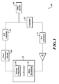
- FIGURE 1 is a diagram of an accelerometer system in accordance with an example embodiment of the invention.
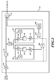
- FIGURE 2 is a diagram showing additional detail for some controller components of the accelerometer system of FIGURE 1 in accordance with an example embodiment of the invention
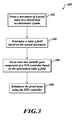
- FIGURE 3 is a flowchart of a method of controlling a closed-loop accelerometer system in accordance with an example embodiment of the invention.
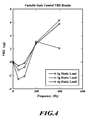
- FIGURE 4 is a chart showing VRE vs. frequency for various static g levels in a modeled accelerometer system that includes a variable gain PID controller in accordance with an embodiment of the invention.
- FIGURE 1 is a diagram of an accelerometer system 20 in accordance with an example embodiment of the invention.
- the accelerometer system 20 includes an accelerometer 22 having at least one sensing component 24, such as a sense plate, and at least one drive mechanism 26 that responds to drive signals in a nonlinear manner.
- the drive mechanism 26 includes an electrostatic capacitive drive mechanism in an example embodiment.
- Various types of accelerometers such as microelectromechanical (MEMS) based accelerometers and in particular MEMS based accelerometers having a teeter-totter type construction may be used, for example.
- a sense electronics circuit 28 (details not shown) is in signal communication with the sensing component 24.
- the sense electronics circuit 28 may amplify and filter signals from the sensing component 24, for example.
- the sense electronics circuit 28 is an analog circuit that provides an output to an analog to digital (A/D) converter 30 that digitizes the amplified and filtered signal from the sense electronics 26.
- A/D analog to digital
- a controller 32 receives the digital signal from the A/D converter 30 and generates control signals that are converted by a digital to analog (D/A) converter 34.
- An amplifier 36 takes the output of the D/A converter 34 as an input and amplifies the signal before it is output to the drive mechanism 26.
- the controller 32 includes a proportional-integral-derivative (PID) control component with variable proportional (P) and derivative (D) gain components in an example embodiment.
- P and D gain components are based on a predetermined linear relationship of optimal P and D gain over a range of frequencies, such as 50 Hertz (Hz) to 400 Hz, in relation to a static g field experienced by the accelerometer system 20.
- the predetermined linear relationship of optimal P and D gain is based on a particular optimal P value and a particular optimal D value at each static g field level that minimizes VRE over a range of frequencies, with the linear relationship being defined by a change in the particular optimal P and D values over a range of static g field levels, such as 1g to 4g.
- the controller 32 can reduce VRE in a more effective manner over a range of static g fields than previous PID controllers with constant P and D values that are typically optimized for a particular static g field level.
- the controller 32 is capable of operation outside this range in some embodiments, such as from 0g to a predetermined maximum static field level, while still using the predetermined linear relationship of optimal P and D gain based on the 1g to 4g range.
- the linear relationship may be determined using different static g field ranges in other embodiments.
- FIGURE 2 is a diagram showing additional detail for the controller 32 of the accelerometer system of FIGURE 1 in accordance with an example embodiment of the invention.
- the components of the controller 32 shown in FIGURE 2 may be implemented using analog or digital components, and may be implemented using a combination of software and hardware or in hardware alone.
- a first amplifier 50 takes a signal from the A/D converter 30 as input and amplifies the signal with a predetermined main gain value to generate a main amplified signal output.
- An integrator 52 is in signal communication with the first amplifier 50. The integrator 52 integrates the main amplified signal output to generate an integrator output.
- a first adder 54 accepts three inputs, including the integrator output as a first input.
- An absolute value component 56 is also in signal communication with the integrator output. The absolute value component 56 takes the integrator output as an input and generates an integrator output magnitude.
- a variable derivative gain component 58 takes the integrator output magnitude from the absolute value component 56 as an input and generates a variable derivative gain.
- a first multiplier 62 accepts the variable derivative gain and the main amplified signal output as inputs to generate an intermediate main derivative gain signal.
- a derivative component 64 accepts the intermediate main derivative gain signal as an input and generates a main derivative gain signal based on a derivative of the intermediate main derivative gain signal. The main derivative gain signal is used as a second input at the first adder 54.
- a variable proportional gain component 60 also takes the integrator output magnitude as an input and generates a variable proportional gain.
- a second multiplier 66 accepts the variable proportional gain and the main amplified signal as inputs and generates a main variable proportional gain signal.
- the main variable proportional gain signal is used as a third input at the first adder 54.
- the first adder 54 sums the integrator output, the main variable derivative gain signal, and the main variable proportional gain signal to generate a summed control signal that is provided to the D/A converter 34.
- + B Dg ain ) ⁇ 1/( ⁇ n 2 ) and the variable proportional gain generated by the variable proportional gain component 60 is described by the equation P gain (g control ) (M Pgain ⁇
- M D gain and B D gain are based on a previously determined linear relationship of optimal derivative gain in relation to static field and MP gain and BP gain are based on a previously determined linear relationship of optimal proportional gain in relation to static field.
- ⁇ n is the accelerometer 22 natural frequency
- ⁇ n 2 is the accelerometer 22 natural frequency squared
- Q is the damping factor of the accelerometer 22.
- variable derivative gain component 58 includes an initial derivative gain amplifier 68 that amplifies the integrator output magnitude by a factor of M D gain to generate an initial derivative gain output.
- a derivative gain adder 70 sums two inputs to generate a summed derivative gain output.
- the initial derivative gain output is taken as a first input by the derivative gain adder 70 and a value of B D gain is taken as a second input from a storage component 72 in signal communication with the derivative gain adder 70.
- the storage component 72 may be a non-volatile memory device, for example.
- the summed derivative gain output is amplified at a final derivative gain amplifier 74 by a factor of 1/( ⁇ n 2 ) to generate the variable derivative gain.
- variable proportional gain component 60 includes a first proportional gain amplifier 76 that amplifies the integrator output magnitude by a factor of M P gain to generate a first proportional gain output.
- a proportional gain adder 78 sums two inputs to generate a summed proportional gain output.
- the first proportional gain output is taken as a first input by the proportional gain adder 78 and a value of B P gain is taken as a second input from a storage component 80 in signal communication with the proportional gain adder 78.
- the storage component 80 may be a non-volatile memory device, for example.
- the summed proportional gain output is amplified at a second proportional gain amplifier 82 by a factor of 1/( ⁇ n ⁇ Q) to generate the variable proportional gain.
- FIGURE 3 is a flowchart of a method 200 of controlling the closed-loop accelerometer system 20 in accordance with an example embodiment of the invention.
- a movement of a proof mass is sensed, such as with the sensing component 24 and the sense electronics 28, for example.
- a static g field is determined based on the sensed movement.
- at least one variable gain component of a PID controller such as the controller 32, for example, is set based on the determined static g field.
- the proof mass is rebalanced using the PID controller.
- setting at least one variable gain component includes setting a variable P component and a variable D component of the PID controller based on a predetermined linear relationship of optimal proportional and derivative gain factors to static g field magnitude.
- rebalancing the proof mass using the PID controller includes sending a control signal to an electrostatic driver that responds in a nonlinear manner, such as the drive mechanism 26.
- FIGURE 4 is a chart showing VRE in micro g ( ⁇ g) vs. frequency in Hz. for various static g levels in a modeled accelerometer system similar to the accelerometer system 20 that includes a variable gain PID controller similar to the controller 32 in accordance with an embodiment of the invention.
- controller 32 may be implemented using various combinations of analog and digital hardware and/or software that may include microcontrollers, field programmable gate arrays (FPGAs), application specific integrated circuits (ASICs), or systems on a chip (SOCs), for example. Additionally, in some embodiments, different numbers of derivative and/or proportional gain amplifiers than those described with reference to FIGURE 2 may be used. Also, the systems and methods may be based on a predetermined linear relationship of P and D gain values over a frequency range other than 50 to 400 Hz and g field values of 1g to 4g in some embodiments.
Landscapes
- Physics & Mathematics (AREA)
- General Physics & Mathematics (AREA)
- Feedback Control In General (AREA)
- Vibration Prevention Devices (AREA)
- Control Of Position Or Direction (AREA)
- Micromachines (AREA)
- Apparatuses For Generation Of Mechanical Vibrations (AREA)
Applications Claiming Priority (1)
| Application Number | Priority Date | Filing Date | Title |
|---|---|---|---|
| US12/201,999 US8086328B2 (en) | 2008-08-29 | 2008-08-29 | Systems and methods for vibration rectification error reduction in closed-loop accelerometer systems |
Publications (2)
| Publication Number | Publication Date |
|---|---|
| EP2159579A1 true EP2159579A1 (de) | 2010-03-03 |
| EP2159579B1 EP2159579B1 (de) | 2010-12-29 |
Family
ID=41051146
Family Applications (1)
| Application Number | Title | Priority Date | Filing Date |
|---|---|---|---|
| EP09168620A Active EP2159579B1 (de) | 2008-08-29 | 2009-08-25 | Systeme und Verfahren für Schwingungkorrigierung-Fehlerverminderung in den Beschleunigungsmesser-Systemen mit geschlossenem Regelkreis |
Country Status (5)
| Country | Link |
|---|---|
| US (1) | US8086328B2 (de) |
| EP (1) | EP2159579B1 (de) |
| JP (1) | JP5769368B2 (de) |
| AT (1) | ATE493664T1 (de) |
| DE (1) | DE602009000491D1 (de) |
Cited By (1)
| Publication number | Priority date | Publication date | Assignee | Title |
|---|---|---|---|---|
| EP2808684A1 (de) * | 2013-05-31 | 2014-12-03 | Honeywell International Inc. | Beschleunigungsmesser mit erweitertem Messbereich und geschlossenem Regelkreis |
Families Citing this family (10)
| Publication number | Priority date | Publication date | Assignee | Title |
|---|---|---|---|---|
| US8373387B2 (en) | 2010-08-03 | 2013-02-12 | The Gillette Company | USB inductive charger |
| FR2983574B1 (fr) * | 2011-12-06 | 2014-01-10 | Sagem Defense Securite | Capteur angulaire inertiel de type mems equilibre et procede d'equilibrage d'un tel capteur |
| JP6358913B2 (ja) * | 2014-09-30 | 2018-07-18 | 株式会社日立製作所 | 加速度センサ |
| RU2573615C1 (ru) * | 2014-11-20 | 2016-01-20 | Федеральное государственное бюджетное образовательное учреждение высшего профессионального образования "Нижегородский государственный технический университет им. Р.Е. Алексеева", НГТУ | Микромеханический демпфер |
| CN111308896B (zh) * | 2015-05-25 | 2021-07-13 | 中国科学院自动化研究所 | 基于可变误差的非线性系统自适应最优控制方法 |
| CN111289773B (zh) * | 2018-12-06 | 2022-08-09 | 航天科工惯性技术有限公司 | 一种加速度计振动整流误差试验装置及方法 |
| CN114995111B (zh) * | 2022-06-13 | 2025-11-21 | 四川知微传感技术有限公司 | 一种电容式接口闭环控制读出电路 |
| US12487248B2 (en) | 2022-09-16 | 2025-12-02 | Simmonds Precision Products, Inc. | MEMS accelerometer systems |
| CN116165878B (zh) * | 2022-12-15 | 2025-04-11 | 浙江大学 | 一种数字加速度计伺服控制系统的自动化pid参数整定方法 |
| US12510556B2 (en) | 2023-04-11 | 2025-12-30 | Atlantic Inertial Systems, Inc. | Micro-electrical-mechanical-systems (MEMS) accelerometer systems |
Citations (3)
| Publication number | Priority date | Publication date | Assignee | Title |
|---|---|---|---|---|
| US5831164A (en) | 1997-01-21 | 1998-11-03 | Conrad Technologies, Inc. | Linear and rotational accelerometer |
| WO2006036897A1 (en) | 2004-09-28 | 2006-04-06 | Honeywell International Inc. | Methods and apparatus for reducing vibration rectification errors in closed-loop accelerometers |
| GB2421083A (en) | 2004-12-09 | 2006-06-14 | Boeing Co | Magnetic Null Accelerometer |
Family Cites Families (13)
| Publication number | Priority date | Publication date | Assignee | Title |
|---|---|---|---|---|
| JPS62157575A (ja) * | 1985-12-30 | 1987-07-13 | Canon Inc | サ−ボ加速度計 |
| JPH0367302A (ja) * | 1989-08-04 | 1991-03-22 | Mitsubishi Electric Corp | オートチューニングコントローラ |
| JP2711790B2 (ja) * | 1993-04-05 | 1998-02-10 | 鹿島建設株式会社 | 振動計測器 |
| JP3409197B2 (ja) * | 1994-11-30 | 2003-05-26 | 株式会社トキメック | 加速度計 |
| JPH11215883A (ja) * | 1998-01-26 | 1999-08-06 | Toyo Electric Mfg Co Ltd | 2慣性共振系トルク制御方法 |
| JP4488471B2 (ja) * | 2001-06-19 | 2010-06-23 | 株式会社ミツトヨ | サーボ型振動検出器 |
| JP2004361388A (ja) * | 2003-05-15 | 2004-12-24 | Mitsubishi Electric Corp | 容量型慣性力検出装置 |
| JP4490671B2 (ja) * | 2003-11-11 | 2010-06-30 | 日立オートモティブシステムズ株式会社 | 位置制御装置 |
| JP2006162495A (ja) * | 2004-12-09 | 2006-06-22 | Seiko Instruments Inc | 力学量センサ |
| US7444868B2 (en) * | 2006-06-29 | 2008-11-04 | Honeywell International Inc. | Force rebalancing for MEMS inertial sensors using time-varying voltages |
| US8947526B2 (en) * | 2006-12-07 | 2015-02-03 | Sensormatic Electronics, LLC | Video surveillance system having communication acknowledgement nod |
| US7984648B2 (en) * | 2008-04-10 | 2011-07-26 | Honeywell International Inc. | Systems and methods for acceleration and rotational determination from an in-plane and out-of-plane MEMS device |
| US8020440B2 (en) * | 2008-05-16 | 2011-09-20 | Rosemount Aerospace Inc. | System and method for providing high-range capability with closed-loop inertial sensors |
-
2008
- 2008-08-29 US US12/201,999 patent/US8086328B2/en active Active
-
2009
- 2009-08-25 AT AT09168620T patent/ATE493664T1/de not_active IP Right Cessation
- 2009-08-25 EP EP09168620A patent/EP2159579B1/de active Active
- 2009-08-25 DE DE602009000491T patent/DE602009000491D1/de active Active
- 2009-08-27 JP JP2009196875A patent/JP5769368B2/ja not_active Expired - Fee Related
Patent Citations (3)
| Publication number | Priority date | Publication date | Assignee | Title |
|---|---|---|---|---|
| US5831164A (en) | 1997-01-21 | 1998-11-03 | Conrad Technologies, Inc. | Linear and rotational accelerometer |
| WO2006036897A1 (en) | 2004-09-28 | 2006-04-06 | Honeywell International Inc. | Methods and apparatus for reducing vibration rectification errors in closed-loop accelerometers |
| GB2421083A (en) | 2004-12-09 | 2006-06-14 | Boeing Co | Magnetic Null Accelerometer |
Non-Patent Citations (2)
| Title |
|---|
| KRAFT M ET AL: "Closed-loop silicon accelerometers", IEE PROCEEDINGS: CIRCUITS DEVICES AND SYSTEMS, INSTITUTION OF ELECTRICAL ENGINEERS, STENVENAGE, GB, vol. 145, no. 5, 5 October 1998 (1998-10-05), pages 325 - 331, XP006010797, ISSN: 1350-2409 * |
| M. KRAFT, IEE PROCEEDINGS: CIRCUITS DEVICES SYSTEMS, vol. 145, no. FIVE, October 1998 (1998-10-01), pages 325 - 331 |
Cited By (2)
| Publication number | Priority date | Publication date | Assignee | Title |
|---|---|---|---|---|
| EP2808684A1 (de) * | 2013-05-31 | 2014-12-03 | Honeywell International Inc. | Beschleunigungsmesser mit erweitertem Messbereich und geschlossenem Regelkreis |
| US9383384B2 (en) | 2013-05-31 | 2016-07-05 | Honeywell International Inc. | Extended-range closed-loop accelerometer |
Also Published As
| Publication number | Publication date |
|---|---|
| JP5769368B2 (ja) | 2015-08-26 |
| US20100057224A1 (en) | 2010-03-04 |
| EP2159579B1 (de) | 2010-12-29 |
| JP2010054508A (ja) | 2010-03-11 |
| DE602009000491D1 (de) | 2011-02-10 |
| ATE493664T1 (de) | 2011-01-15 |
| US8086328B2 (en) | 2011-12-27 |
Similar Documents
| Publication | Publication Date | Title |
|---|---|---|
| EP2159579A1 (de) | Systeme und Verfahren für Schwingungkorrigierung-Fehlerverminderung in den Beschleunigungsmesser-Systemen mit geschlossenem Regelkreis | |
| JP7477670B2 (ja) | 床フィードフォワード補助を備えた精密振動絶縁システム | |
| US10585112B2 (en) | Acceleration sensor | |
| CN101790675B (zh) | 绝对位移检测方法和使用该方法的绝对位移传感器 | |
| US10473691B2 (en) | Offset cancellation device for micro-electromechanical system | |
| JP2010058541A (ja) | 状態推定装置、サスペンション制御装置及びサスペンションシステム | |
| EP2762894B1 (de) | Beschleunigungssensorschaltung | |
| US12196602B2 (en) | Infrasound detector with force transducer for negative feedback or calibration | |
| CN106844291B (zh) | 用于控制和协同仿真实体系统的方法和系统 | |
| US11619492B2 (en) | Sensor linearization based upon correction of static and frequency-dependent non-linearities | |
| CN108140378A (zh) | 扩展的噪声和振动感测 | |
| Chang et al. | Effective suppression of pneumatic vibration isolators by using input–output linearization and time delay control | |
| Soen et al. | Controller design for a closed-loop micromachined accelerometer | |
| CN102210098B (zh) | Dc稳定的电荷放大器 | |
| JPH05180661A (ja) | センサ信号抽出回路 | |
| JP3360935B2 (ja) | 電動機制御系における機械共振検出装置及び制振制御装置 | |
| JP5043726B2 (ja) | サーボ型振動計 | |
| JP7288841B2 (ja) | センサシステム、および該センサシステムを備える除振装置 | |
| JP3820495B2 (ja) | アクティブ免震装置 | |
| KR20170093528A (ko) | 능동질량감쇠시스템 및 이를 이용한 구조물의 진동 제어 방법 | |
| US20260115907A1 (en) | Method for suppressing vibration of control signal for force control, computer device and readable storage medium | |
| JPH0712175A (ja) | 精密防振装置 | |
| JP2012247349A (ja) | センサ装置 | |
| KR100698722B1 (ko) | 자동차의 모터 전류 제어장치 | |
| JP5034624B2 (ja) | 角速度センサ |
Legal Events
| Date | Code | Title | Description |
|---|---|---|---|
| PUAI | Public reference made under article 153(3) epc to a published international application that has entered the european phase |
Free format text: ORIGINAL CODE: 0009012 |
|
| 17P | Request for examination filed |
Effective date: 20090825 |
|
| AK | Designated contracting states |
Kind code of ref document: A1 Designated state(s): AT BE BG CH CY CZ DE DK EE ES FI FR GB GR HR HU IE IS IT LI LT LU LV MC MK MT NL NO PL PT RO SE SI SK SM TR |
|
| AX | Request for extension of the european patent |
Extension state: AL BA RS |
|
| GRAP | Despatch of communication of intention to grant a patent |
Free format text: ORIGINAL CODE: EPIDOSNIGR1 |
|
| GRAS | Grant fee paid |
Free format text: ORIGINAL CODE: EPIDOSNIGR3 |
|
| GRAA | (expected) grant |
Free format text: ORIGINAL CODE: 0009210 |
|
| AK | Designated contracting states |
Kind code of ref document: B1 Designated state(s): AT BE BG CH CY CZ DE DK EE ES FI FR GB GR HR HU IE IS IT LI LT LU LV MC MK MT NL NO PL PT RO SE SI SK SM TR |
|
| REG | Reference to a national code |
Ref country code: GB Ref legal event code: FG4D |
|
| REG | Reference to a national code |
Ref country code: CH Ref legal event code: EP |
|
| REG | Reference to a national code |
Ref country code: IE Ref legal event code: FG4D |
|
| REF | Corresponds to: |
Ref document number: 602009000491 Country of ref document: DE Date of ref document: 20110210 Kind code of ref document: P |
|
| REG | Reference to a national code |
Ref country code: DE Ref legal event code: R096 Ref document number: 602009000491 Country of ref document: DE Effective date: 20110210 |
|
| REG | Reference to a national code |
Ref country code: NL Ref legal event code: VDEP Effective date: 20101229 |
|
| PG25 | Lapsed in a contracting state [announced via postgrant information from national office to epo] |
Ref country code: LT Free format text: LAPSE BECAUSE OF FAILURE TO SUBMIT A TRANSLATION OF THE DESCRIPTION OR TO PAY THE FEE WITHIN THE PRESCRIBED TIME-LIMIT Effective date: 20101229 |
|
| LTIE | Lt: invalidation of european patent or patent extension |
Effective date: 20101229 |
|
| PG25 | Lapsed in a contracting state [announced via postgrant information from national office to epo] |
Ref country code: AT Free format text: LAPSE BECAUSE OF FAILURE TO SUBMIT A TRANSLATION OF THE DESCRIPTION OR TO PAY THE FEE WITHIN THE PRESCRIBED TIME-LIMIT Effective date: 20101229 Ref country code: SE Free format text: LAPSE BECAUSE OF FAILURE TO SUBMIT A TRANSLATION OF THE DESCRIPTION OR TO PAY THE FEE WITHIN THE PRESCRIBED TIME-LIMIT Effective date: 20101229 Ref country code: HR Free format text: LAPSE BECAUSE OF FAILURE TO SUBMIT A TRANSLATION OF THE DESCRIPTION OR TO PAY THE FEE WITHIN THE PRESCRIBED TIME-LIMIT Effective date: 20101229 Ref country code: BG Free format text: LAPSE BECAUSE OF FAILURE TO SUBMIT A TRANSLATION OF THE DESCRIPTION OR TO PAY THE FEE WITHIN THE PRESCRIBED TIME-LIMIT Effective date: 20110329 Ref country code: FI Free format text: LAPSE BECAUSE OF FAILURE TO SUBMIT A TRANSLATION OF THE DESCRIPTION OR TO PAY THE FEE WITHIN THE PRESCRIBED TIME-LIMIT Effective date: 20101229 Ref country code: CY Free format text: LAPSE BECAUSE OF FAILURE TO SUBMIT A TRANSLATION OF THE DESCRIPTION OR TO PAY THE FEE WITHIN THE PRESCRIBED TIME-LIMIT Effective date: 20101229 Ref country code: LV Free format text: LAPSE BECAUSE OF FAILURE TO SUBMIT A TRANSLATION OF THE DESCRIPTION OR TO PAY THE FEE WITHIN THE PRESCRIBED TIME-LIMIT Effective date: 20101229 Ref country code: SI Free format text: LAPSE BECAUSE OF FAILURE TO SUBMIT A TRANSLATION OF THE DESCRIPTION OR TO PAY THE FEE WITHIN THE PRESCRIBED TIME-LIMIT Effective date: 20101229 |
|
| PG25 | Lapsed in a contracting state [announced via postgrant information from national office to epo] |
Ref country code: EE Free format text: LAPSE BECAUSE OF FAILURE TO SUBMIT A TRANSLATION OF THE DESCRIPTION OR TO PAY THE FEE WITHIN THE PRESCRIBED TIME-LIMIT Effective date: 20101229 Ref country code: PT Free format text: LAPSE BECAUSE OF FAILURE TO SUBMIT A TRANSLATION OF THE DESCRIPTION OR TO PAY THE FEE WITHIN THE PRESCRIBED TIME-LIMIT Effective date: 20110429 Ref country code: BE Free format text: LAPSE BECAUSE OF FAILURE TO SUBMIT A TRANSLATION OF THE DESCRIPTION OR TO PAY THE FEE WITHIN THE PRESCRIBED TIME-LIMIT Effective date: 20101229 Ref country code: IS Free format text: LAPSE BECAUSE OF FAILURE TO SUBMIT A TRANSLATION OF THE DESCRIPTION OR TO PAY THE FEE WITHIN THE PRESCRIBED TIME-LIMIT Effective date: 20110429 Ref country code: GR Free format text: LAPSE BECAUSE OF FAILURE TO SUBMIT A TRANSLATION OF THE DESCRIPTION OR TO PAY THE FEE WITHIN THE PRESCRIBED TIME-LIMIT Effective date: 20110330 Ref country code: NO Free format text: LAPSE BECAUSE OF FAILURE TO SUBMIT A TRANSLATION OF THE DESCRIPTION OR TO PAY THE FEE WITHIN THE PRESCRIBED TIME-LIMIT Effective date: 20110329 Ref country code: ES Free format text: LAPSE BECAUSE OF FAILURE TO SUBMIT A TRANSLATION OF THE DESCRIPTION OR TO PAY THE FEE WITHIN THE PRESCRIBED TIME-LIMIT Effective date: 20110409 Ref country code: CZ Free format text: LAPSE BECAUSE OF FAILURE TO SUBMIT A TRANSLATION OF THE DESCRIPTION OR TO PAY THE FEE WITHIN THE PRESCRIBED TIME-LIMIT Effective date: 20101229 |
|
| PG25 | Lapsed in a contracting state [announced via postgrant information from national office to epo] |
Ref country code: NL Free format text: LAPSE BECAUSE OF FAILURE TO SUBMIT A TRANSLATION OF THE DESCRIPTION OR TO PAY THE FEE WITHIN THE PRESCRIBED TIME-LIMIT Effective date: 20101229 Ref country code: SK Free format text: LAPSE BECAUSE OF FAILURE TO SUBMIT A TRANSLATION OF THE DESCRIPTION OR TO PAY THE FEE WITHIN THE PRESCRIBED TIME-LIMIT Effective date: 20101229 Ref country code: RO Free format text: LAPSE BECAUSE OF FAILURE TO SUBMIT A TRANSLATION OF THE DESCRIPTION OR TO PAY THE FEE WITHIN THE PRESCRIBED TIME-LIMIT Effective date: 20101229 Ref country code: PL Free format text: LAPSE BECAUSE OF FAILURE TO SUBMIT A TRANSLATION OF THE DESCRIPTION OR TO PAY THE FEE WITHIN THE PRESCRIBED TIME-LIMIT Effective date: 20101229 |
|
| PG25 | Lapsed in a contracting state [announced via postgrant information from national office to epo] |
Ref country code: DK Free format text: LAPSE BECAUSE OF FAILURE TO SUBMIT A TRANSLATION OF THE DESCRIPTION OR TO PAY THE FEE WITHIN THE PRESCRIBED TIME-LIMIT Effective date: 20101229 |
|
| PLBE | No opposition filed within time limit |
Free format text: ORIGINAL CODE: 0009261 |
|
| STAA | Information on the status of an ep patent application or granted ep patent |
Free format text: STATUS: NO OPPOSITION FILED WITHIN TIME LIMIT |
|
| 26N | No opposition filed |
Effective date: 20110930 |
|
| PG25 | Lapsed in a contracting state [announced via postgrant information from national office to epo] |
Ref country code: MT Free format text: LAPSE BECAUSE OF FAILURE TO SUBMIT A TRANSLATION OF THE DESCRIPTION OR TO PAY THE FEE WITHIN THE PRESCRIBED TIME-LIMIT Effective date: 20101229 |
|
| REG | Reference to a national code |
Ref country code: DE Ref legal event code: R097 Ref document number: 602009000491 Country of ref document: DE Effective date: 20110930 |
|
| PG25 | Lapsed in a contracting state [announced via postgrant information from national office to epo] |
Ref country code: MC Free format text: LAPSE BECAUSE OF NON-PAYMENT OF DUE FEES Effective date: 20110831 |
|
| REG | Reference to a national code |
Ref country code: IE Ref legal event code: MM4A |
|
| PG25 | Lapsed in a contracting state [announced via postgrant information from national office to epo] |
Ref country code: IT Free format text: LAPSE BECAUSE OF FAILURE TO SUBMIT A TRANSLATION OF THE DESCRIPTION OR TO PAY THE FEE WITHIN THE PRESCRIBED TIME-LIMIT Effective date: 20101229 |
|
| REG | Reference to a national code |
Ref country code: DE Ref legal event code: R119 Ref document number: 602009000491 Country of ref document: DE Effective date: 20120301 |
|
| PG25 | Lapsed in a contracting state [announced via postgrant information from national office to epo] |
Ref country code: IE Free format text: LAPSE BECAUSE OF NON-PAYMENT OF DUE FEES Effective date: 20110825 |
|
| PG25 | Lapsed in a contracting state [announced via postgrant information from national office to epo] |
Ref country code: MK Free format text: LAPSE BECAUSE OF FAILURE TO SUBMIT A TRANSLATION OF THE DESCRIPTION OR TO PAY THE FEE WITHIN THE PRESCRIBED TIME-LIMIT Effective date: 20101229 |
|
| PG25 | Lapsed in a contracting state [announced via postgrant information from national office to epo] |
Ref country code: SM Free format text: LAPSE BECAUSE OF FAILURE TO SUBMIT A TRANSLATION OF THE DESCRIPTION OR TO PAY THE FEE WITHIN THE PRESCRIBED TIME-LIMIT Effective date: 20101229 |
|
| PG25 | Lapsed in a contracting state [announced via postgrant information from national office to epo] |
Ref country code: LU Free format text: LAPSE BECAUSE OF NON-PAYMENT OF DUE FEES Effective date: 20110825 |
|
| PG25 | Lapsed in a contracting state [announced via postgrant information from national office to epo] |
Ref country code: DE Free format text: LAPSE BECAUSE OF NON-PAYMENT OF DUE FEES Effective date: 20120301 |
|
| PG25 | Lapsed in a contracting state [announced via postgrant information from national office to epo] |
Ref country code: TR Free format text: LAPSE BECAUSE OF FAILURE TO SUBMIT A TRANSLATION OF THE DESCRIPTION OR TO PAY THE FEE WITHIN THE PRESCRIBED TIME-LIMIT Effective date: 20101229 |
|
| PG25 | Lapsed in a contracting state [announced via postgrant information from national office to epo] |
Ref country code: HU Free format text: LAPSE BECAUSE OF FAILURE TO SUBMIT A TRANSLATION OF THE DESCRIPTION OR TO PAY THE FEE WITHIN THE PRESCRIBED TIME-LIMIT Effective date: 20101229 |
|
| REG | Reference to a national code |
Ref country code: CH Ref legal event code: PL |
|
| GBPC | Gb: european patent ceased through non-payment of renewal fee |
Effective date: 20130825 |
|
| PG25 | Lapsed in a contracting state [announced via postgrant information from national office to epo] |
Ref country code: CH Free format text: LAPSE BECAUSE OF NON-PAYMENT OF DUE FEES Effective date: 20130831 Ref country code: LI Free format text: LAPSE BECAUSE OF NON-PAYMENT OF DUE FEES Effective date: 20130831 |
|
| PG25 | Lapsed in a contracting state [announced via postgrant information from national office to epo] |
Ref country code: GB Free format text: LAPSE BECAUSE OF NON-PAYMENT OF DUE FEES Effective date: 20130825 |
|
| REG | Reference to a national code |
Ref country code: FR Ref legal event code: PLFP Year of fee payment: 8 |
|
| REG | Reference to a national code |
Ref country code: FR Ref legal event code: PLFP Year of fee payment: 9 |
|
| REG | Reference to a national code |
Ref country code: FR Ref legal event code: PLFP Year of fee payment: 10 |
|
| P01 | Opt-out of the competence of the unified patent court (upc) registered |
Effective date: 20230525 |
|
| PGFP | Annual fee paid to national office [announced via postgrant information from national office to epo] |
Ref country code: FR Payment date: 20250825 Year of fee payment: 17 |