EP2159689A1 - Contrôleur d'exécution d'instructions et procédé de commande d'exécution d'instructions - Google Patents
Contrôleur d'exécution d'instructions et procédé de commande d'exécution d'instructions Download PDFInfo
- Publication number
- EP2159689A1 EP2159689A1 EP07790179A EP07790179A EP2159689A1 EP 2159689 A1 EP2159689 A1 EP 2159689A1 EP 07790179 A EP07790179 A EP 07790179A EP 07790179 A EP07790179 A EP 07790179A EP 2159689 A1 EP2159689 A1 EP 2159689A1
- Authority
- EP
- European Patent Office
- Prior art keywords
- thread
- entry
- instruction
- reservation station
- executed
- Prior art date
- Legal status (The legal status is an assumption and is not a legal conclusion. Google has not performed a legal analysis and makes no representation as to the accuracy of the status listed.)
- Withdrawn
Links
Images









Classifications
-
- G—PHYSICS
- G06—COMPUTING OR CALCULATING; COUNTING
- G06F—ELECTRIC DIGITAL DATA PROCESSING
- G06F9/00—Arrangements for program control, e.g. control units
- G06F9/06—Arrangements for program control, e.g. control units using stored programs, i.e. using an internal store of processing equipment to receive or retain programs
- G06F9/30—Arrangements for executing machine instructions, e.g. instruction decode
- G06F9/38—Concurrent instruction execution, e.g. pipeline or look ahead
- G06F9/3836—Instruction issuing, e.g. dynamic instruction scheduling or out of order instruction execution
- G06F9/3851—Instruction issuing, e.g. dynamic instruction scheduling or out of order instruction execution from multiple instruction streams, e.g. multistreaming
-
- G—PHYSICS
- G06—COMPUTING OR CALCULATING; COUNTING
- G06F—ELECTRIC DIGITAL DATA PROCESSING
- G06F9/00—Arrangements for program control, e.g. control units
- G06F9/06—Arrangements for program control, e.g. control units using stored programs, i.e. using an internal store of processing equipment to receive or retain programs
- G06F9/30—Arrangements for executing machine instructions, e.g. instruction decode
- G06F9/38—Concurrent instruction execution, e.g. pipeline or look ahead
-
- G—PHYSICS
- G06—COMPUTING OR CALCULATING; COUNTING
- G06F—ELECTRIC DIGITAL DATA PROCESSING
- G06F9/00—Arrangements for program control, e.g. control units
- G06F9/06—Arrangements for program control, e.g. control units using stored programs, i.e. using an internal store of processing equipment to receive or retain programs
- G06F9/30—Arrangements for executing machine instructions, e.g. instruction decode
- G06F9/38—Concurrent instruction execution, e.g. pipeline or look ahead
- G06F9/3836—Instruction issuing, e.g. dynamic instruction scheduling or out of order instruction execution
-
- G—PHYSICS
- G06—COMPUTING OR CALCULATING; COUNTING
- G06F—ELECTRIC DIGITAL DATA PROCESSING
- G06F9/00—Arrangements for program control, e.g. control units
- G06F9/06—Arrangements for program control, e.g. control units using stored programs, i.e. using an internal store of processing equipment to receive or retain programs
- G06F9/30—Arrangements for executing machine instructions, e.g. instruction decode
- G06F9/38—Concurrent instruction execution, e.g. pipeline or look ahead
- G06F9/3854—Instruction completion, e.g. retiring, committing or graduating
Definitions
- the present invention relates to an instruction execution control device and instruction execution control method which controls instructions in an out-of-order processing during an operation of a plurality of threads operate in a simultaneous multi-thread system, and more particularly to an instruction execution control device and an instruction execution control method for preventing generation of a hang state during the operation in the simultaneous multi-thread system.
- the out-of-order execution system is a technology to improve performance of a CPU by executing a subsequent instruction first if data required for the first instruction is not completed and data required for the subsequent instruction processing is completed (e.g. see Patent Document 1) .
- a first instruction processing 1 is an instruction involving memory access
- a subsequent instruction processing 2 is an instruction which does not involve memory access
- the instruction processing 2 is executed in parallel with the memory access of the instruction processing 1, and the instruction processing 1 is executed after executing the instruction processing 2.
- VMT Very Multi-Threading
- VMT Very Multi-Threading
- programmable resources are provided for the number of programs, but the circuit amount to be added is low, because of running only one program at a time, which is easily implemented.
- a multi-thread system is a simultaneous multi-thread (SMT) system which allows a plurality of programs to run simultaneously. Since a plurality of programs run simultaneously, circuit control becomes more difficult and resources increase, compared with the case of allowing a single program to run, but the circuits can be efficiently used since a plurality of programs run at the same time.
- SMT simultaneous multi-thread
- Controlling the reservation station for processing the out-of-order execution allows an execution of functions from an entry which is ready for executing the function, with priority.
- the reservation station controls execution of the entries, so that the timings to output the result of a respective execution of the function do not overlap.
- FIG. 15 is a time chart depicting entry execution control of a reservation station for floating point.
- an execution result of pipeline processing is stored in a result register, and at this time, the reservation station selects an entry to be executed so that the timing to be stored in the result register does not overlap with storing the timing of another execution result.
- FIG. 15 depicts a control example of a subsequent instruction when an entry to be executed by the reservation station is an entry which requires 4 cycles for execution (precedent instruction), and the subsequent instruction is an entry which requires 2 cycles for execution.
- T1 to T7 are cycles
- P is a processing to select an entry to be executed from the reservation station
- B is a processing to read operand data required for executing a function
- X is a processing to store the execution result in the result register in the function execution and last cycle
- U is a processing to store the function execution result in the register update buffer.
- the precedent instruction requires 4 cycles: X1, X2, X3 and X4 for executing a function
- the subsequent instruction requires 2 cycles: X1 and X2 for executing a function.
- the reservation station selects the precedent instruction in cycle T1
- the U processing does not overlap, so the subsequent instruction requiring 2 cycles can be executed at timing T2.
- the timing T7 to store the execution result in the result register (U processing)
- the subsequent instruction cannot be executed here.
- the subsequent instruction requiring 2 cycles can be executed.
- FIG. 16 depicts an example of executing an entry operating in a single thread by the selection operation of the reservation station under this pipeline control.
- the meaning of P, B, X and U in FIG. 16 is the same as those in FIG. 15 .
- FIG. 16 is a time chart when an entry requiring 4 cycles for execution is continuously selected by the reservation station, and in this state, an entry requiring 2 cycles for execution is decoded by the instruction decoder, and then an entry requiring 4 cycles for execution is continuously decoded by the instruction decoder.
- the reservation station issues (executes) entries sequentially as an entry becomes ready for execution. When there are a plurality of entries that can be executed at the same time, the entries are selected and executed in the decoded sequence.
- the entry may not become an entry which can be executed depending on the result output timing of the previous entry being executed.
- the instruction cannot be completed because the entry cannot be issued from the reservation station.
- a subsequent instruction can be executed from the reservation station, but the instruction cannot be completed.
- the entry having the function to control completion of an instruction becomes FULL state, and instructions cannot be decoded by the instruction decoder (instruction decoder stopping state). Since an instruction is not decoded and a new entry cannot be created in the reservation station, the entry which cannot be executed (entry having 2 cycles in FIG. 16 ) can be executed in cycle T5, for example, and the instruction can be completed.
- FIG. 17 is an example when an entry requiring 4 cycles for execution is executed continuously from the reservation station, and an instruction requiring 4 cycles for execution is decoded by the instruction decoder in the thread 0, in a state of threads 0 and 1 operating in the simultaneous multi-thread.
- the instruction in the thread 0 can be completed even after the instruction is executed, so the instruction decoder can decode the instruction in the thread 0. Hence the thread 0 can continuously operate without stopping.
- an object of the present invention to provide an instruction execution control device and an instruction execution control method to enable execution of an entry in the reservation station before the hang state occurs in the processing of the simultaneous multi-thread system.
- this invention provides an instruction execution control device, which operates a plurality of thread in a simultaneous multi-thread system and executes an instruction control in an out of order processing, including: an instruction decoder for decoding an instruction; a computing processing reservation station which receives a decoding result from the instruction decoder, and controls computing processing; a main storage reservation station which controls the generation of an address of an operand to be stored in a main storage; an instruction control mechanism which controls executed instructions so that the instructions are completed according to the sequence of a program; and a hang prevention circuit which, when the instruction control mechanism detects that an instruction in one thread cannot be completed in a predetermined period, selects a thread of an entry that can be executed from all of the reservation stations to be the same as the thread of which incompletion in the predetermined period has been detected.
- this invention provides an instruction execution control method which operates a plurality of thread in a simultaneous multi-thread system and executes an instruction control in an out of order processing, including: a step of creating an entry by a computing processing reservation station based on a decoding result by an instruction decoder, and issuing an entry which is ready for execution to a computing processing mechanism; a step of creating an entry from the instruction by a main storage reservation station which controls the generation of an address of an operand to be stored in a main storage, and issuing an entry which is ready for execution to a main storage operand address generator; a step of controlling the executed instructions so that the instructions are completed according to the sequence of a program; and a step of, when it is detected that an instruction in one thread cannot be completed in a predetermined period, selecting a thread of an entry that can be executed from all of the reservation stations to be the same as the thread of which incompletion in the predetermined period has been detected.
- the hang prevention circuit includes a thread selection circuit which, when it is detected to have not completed the thread in the predetermined period, selects a thread of an entry that is executed from the reservation station to be the same as the thread of which incompletion in the predetermined period has been detected.
- the hang prevention circuit further includes an executability selection circuit which, when a thread selected by the thread selection circuit matches with a thread of an entry of the reservation station, enables the entry to be executed from the reservation station.
- the thread selection circuit is constructed as a thread selection circuit which changes a thread to be selected depending on an elapsed time.
- the thread selection circuit prohibits selecting a thread which is not operating based on a signal to indicate a thread which is operating.
- the hang prevention circuit stops the control of the reservation station when the uncompleted instruction is completed.
- the reservation station includes: an entry generation circuit which enters an instruction from the instruction decoder to the reservation station; and an execution entry selection circuit which selects an entry that can be executed from the reservation station.
- the computing processing reservation station executes an entry which is ready for execution, at a timing which does not overlap with the timing of executing the precedent entry or the timing of storing the execution result of the precedent entry.
- a state where an instruction is not completed for a predetermined period is detected during simultaneous multi-thread operation, and it is controlled so that all the reservation stations can execute only a predetermined thread, therefore if an entry that cannot be executed from the reservation station exists, execution of an entry in the thread that cannot be executed can be enabled by stopping the execution of the thread which has been continuously executed.
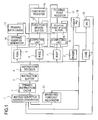
- FIG. 1 is an overview of an embodiment of an information processing device according to the present invention. As FIG. 1 depicts, a primary instruction cache 2 and a primary data cache 11 are connected to a secondary cache, in connection with a main storage, which is not illustrated.
- an instruction fetch address generator 1 selects an instruction address and sends an instruction fetch request for the selected instruction address to the primary instruction cache 2.
- the instruction fetched from the primary instruction cache 2 is stored in an instruction buffer 3.
- the stored instructions are supplied to an instruction decoder 4 in the execution sequence of the program from the instruction buffer 3.
- the instruction decoder 4 decodes the instructions according to the execution sequence of the program. Depending on the type of instruction to be decoded, the instruction decoder 4 creates a required entry for a reservation station unit for generating a main storage operand address (RSA: Reservation Station for Address generate) 5, a reservation station unit for computing a fixed point (RSE: Reservation Station for Execute) 6, a reservation station unit for computing a floating point (RSF: Reservation Station for Floating) 7, and a reservation station unit for branch instruction (RSBR (Reservation Station for BRanch) 8, which controls execution of instructions.
- RSA Reservation Station for Address generate
- RSE Reservation Station for Execute
- RSF Reservation Station for Execute
- RSF Reservation Station for Floating
- RSBR Reservation Station for BRanch
- the instruction decoder 4 decodes a fetched instruction in-order, and the decoded instruction is stored in the reservation station units 5, 6, 7, 8 and 9, which control the execution of functions respectively, depending on the type of instruction.
- a reservation station unit has reservation station units for computing 6 and 7, and reservation station unit for generating a main storage operand address 5.
- CSE Commit Stack Entry
- a decoded instruction is a load instruction when an entry is created in RSA5
- the RSA5 instructs an operand address generator 10 to generate an operand address, reads the corresponding data from the primary data cache 11 to a fixed point update buffer (GUB: General Update Buffer) 13 and a floating point update buffer (FUB: Floating Update Buffer) 16.
- GUI Fixed Point Update Buffer
- FUB floating point update buffer
- each computing unit 12 and 15 is operated so as to execute corresponding computing processing.
- an out-of-order execution can be enabled by renaming registers corresponding to GUB13 and FUB16, and the execution result is stored in GUB13 and FUB16.
- Programmable resources such as a fixed point register 14 and floating point register 17 and program counters (PC, NEXT_PC) 18 and 19, are updated only for the completed instructions.
- the branching forecasting mechanism 21 forecasts branching by an instruction from the reservation station for branching instruction 8, so as to control the instruction fetch address generator 1.
- the reservation station units 5, 6, 7 and 8 selects a thread for each computing cycle, instructs an execution of the selected thread to the operand address generators 10 and computing units 12 and 15, and reads and writes operand data of the thread selected from and to the registers 14 and 17, whereby the simultaneous multi-thread processing is executed.
- FIG. 2 is a block diagram depicting an embodiment of the instruction execution control device of the present invention
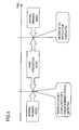
- FIG. 3 is a flow chart depicting an operation of the configuration in FIG. 2
- FIG. 4 is a diagram depicting the operation in FIG. 3
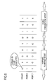
- FIG. 5 is a diagram depicting the execution thread based on the operation in FIG. 2 to FIG. 4
- FIG. 2 is a detailed diagram of RSE5, RSE6 and RSF7 in FIG. 1 .
- the present invention can also be implemented even if the number of threads is three or more.
- FIG. 2 composing elements the same as FIG. 1 are denoted with a same symbol, and the reservation units 5, 6 and 7 are comprised of entry generation circuits 50, 60 and 70, executability selection circuits 52, 62 and 72, reservation stations 54, 64 and 74, and execution entry selection circuits 56, 66 and 76 respectively.
- a thread selection circuit 30 is connected to each of the executability selection circuits 52, 62 and 72.
- the entries in the reservation station units 5, 6 and 7 are used to share the threads 0 and 1.
- an entry stores: a VALID signal to indicate that the entry is valid, a thread ID to indicate a thread of the entry, a signal to indicate to read the operand data from the architecture register and the read address, a signal to indicate to read from the register update buffer and the read address, and an instruction identifier to indicate a number of an instruction to be allocated to each instruction when the instruction is decoded, for example.
- the thread selection circuit 30 switches the running mode to the hang prevention mode, and selects a hang prevention thread ID.
- the executability selection circuit 52, 62 or 72 compares the entries of the entry circuit 50, 60 or 70, and the reservation station 54, 64 or 74 with the thread ID of the thread selection circuit 30, and selects an executable entry.
- the execution entry selection circuit 56, 66 or 76 selects an executable entry from the entries of the reservation station 54, 64 or 74, and issues it to the function execution unit 10, 12 or 15.
- the reservation station 54, 64 or 74 can use out-of-order execution.
- the entries of the reservation station 54, 64 or 74 can execute from the entry of which operand data required for execution has become ready.
- the entry selected by the execution entry selection circuit 46, 56 or 66 for selecting an entry to be executed is executed from the reservation station 54, 64 or 74. If a plurality of entries is ready for execution simultaneously, the execution entry selection circuit 46, 56 or 66 selects and executes an entry in the decoded sequence.
- a function For the entry executed from the reservation station for floating point 74, a function is executed by pipeline processing. The function execution completes, and the function execution result is stored in the result register. Completion of the execution of the function is reported to the function CSE9, which controls completion of instructions.
- the instruction completion control function CSE9 performs control of a complete of the instruction according to the sequence of the program.
- function execution completes, the instruction can be completed, but since the completion control of the instruction are executed according to the sequence of the program, the subsequent instruction cannot be completed even if the execution thereof is completed, unless the oldest instruction is completed.
- the instructions are completed in each thread independently, so the instruction can be completed without being interrupted by other threads.
- the result of function execution by pipeline processing is stored in the result register, but the reservation station 74 selects the entry to be executed such that timings to be stored in the result register does not overlap.
- the thread selection circuit 30 judges whether or not CSE9 transmitted a signal to indicate the detection of an instruction which has not completed for a predetermined time in the normal running state (S10).
- the thread selection 30 receives the signal to indicate detection of an instruction which has not completed for a predetermined time from CSE9, the thread selection 30 changes the running mode to the hang prevention mode (S12).
- the thread selection circuit 30 is not used, so as FIG. 5 depicts, a thread number of the thread of instructions to be executed from each reservation station 5, 6 or 7 is the number of an entry selected by each reservation station 5, 6 or 7 respectively.
- entry selection in the reservation station is not limited to the specific thread, and the thread number for execution differs depending on each reservation station 5, 6 or 7. Since each reservation station 5, 6 or 7 independently selects a thread number, the thread number for execution may accidentally become the same as the thread number selected by another reservation station.
- the thread number selected by the thread selection circuit 30, which operates during the hang prevention mode can be an executable thread number.
- FIG. 5 depicts, thread numbers to be executed from the reservation stations 5, 6 and 7 are controlled to be the same.
- the thread selection circuit 30 When the thread selection circuit 30 is notified from CSE9 that the instruction which could not be completed for a predetermined time completed, the thread selection circuit 30 returns the mode to the normal running mode as depicted in FIG. 4 , and stops the thread selection operation (S14).
- control is performed, however, execution of the entry in a thread which is not in the hang state is stopped, therefore control is performed so that performance does not drop considerably even if the hang state occurs, and then the thread in the hang state is executed.
- FIG. 6 is a block diagram depicting the thread selection circuit 30 in FIG. 2
- FIG. 7 is a flow chart depicting the processing of the executability selection circuit in FIG. 2 and FIG. 6
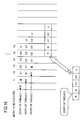
- FIG. 8 is a diagram depicting a thread selection method based on the configuration in FIG. 6
- FIG. 9 is a diagram depicting an execution selection operation of an entry of the reservation station in FIG. 6
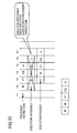
- FIG. 10 is a diagram depicting an execution selection operation of the reservation station for fixed point in FIG. 6 .
- FIG. 6 to FIG. 9 are described using the example of the reservation station unit for floating point 7 in FIG. 2 .
- the reservation station unit for fixed point 6 in FIG. 2 and the reservation unit for generating operand 5 also have the same configuration.
- the configuration of the thread selection circuit 30 will be described with reference to FIG. 6 .
- the thread selection circuit 30 changes the thread number alternately along the time axis, and outputs it.
- the thread selection circuit 30 has a timer counter 32, a thread switching time selection circuit 34, a thread ID generation circuit 36, a thread decision circuit 38, a hang prevention thread ID register 40, and a hang prevention mode start circuit 42.
- the hang prevention mode start circuit 42 starts the thread switching time selection circuit 34, thread decision circuit 38 and executability selection circuits 52, 62 and 72 according to a detection signal when an instruction, which has not completed for a predetermined time, was detected in CSE9 in FIG. 1 .
- the thread switching time selection circuit 34 has a thread switching time to indicate time to select a same thread continuously, and instructs the thread decision circuit 38 to switch the thread when the thread switching time arrives.
- the thread switching time can be changed when a counter value reaches a certain value by the timer counter 32, which increments 1 every 1 cycle.
- the thread decision circuit 38 selects a thread ID of the thread ID generation circuit 36 using the thread switching time and the counter value of the timer counter.
- the thread ID generation circuit 36 outputs a thread ID, which is different from the thread ID of the hang prevention thread ID register 40, to the thread decision circuit 38.
- the thread selected by this thread decision circuit 38 becomes the hang prevention thread ID, and is sent to the executability selection circuit 52, 62 and 72, so as to select an entry which can be executed from the reservation station 54, 64 or 74.
- step S26 it is judged whether or not a thread of the entry of the reservation station 54, 64 or 74 matches with the thread selected by the thread selection circuit 30 in one previous cycle of the execution entry selection circuit 56, 66 or 76 (S22). If there is no match, processing advances to step S26.
- this entry For the entry of which a thread matches, it is judged whether or not this entry is ready for execution, and if ready, this entry is determined as an entry having a possibility to be selected by the execution entry selection circuit 56, 66 or 76 in the next cycle (S24). Then a flag, for example, is assigned to this entry.
- the entry of which a thread does not match with the selected thread is determined as an entry having no possibility to be selected by the execution entry selection circuit in the next cycle (S26).
- step S26 In a cycle where an instruction is decoded and is newly registered in an entry in the reservation station, it is judged whether or not a thread of an entry registered from the entry generation circuit 50, 60 or 70 matches with a thread selected by the thread selection circuit 30 (S20). If there is no match, processing advances to step S26.
- this entry For the entry of which thread matches, it is judged whether or not this entry is ready for execution, and if ready, this entry is decided as an entry having a possibility to be selected by the execution entry selection circuit 56, 66 or 76 in the next cycle (S24). Then a flag, for example, is assigned to this entry.
- the entry of which thread does not match with the selected thread is decided as an entry having no possibility to be selected by the execution entry selection circuit in the next cycle (S26).
- a thread selection example by the thread selection circuit 30 will be described with reference to FIG. 8 .
- the hang prevention mode starts, and the thread selection circuit 30 is activated.
- the thread switching time After entering the hang prevention mode, the thread switching time initially becomes 1 cycle mode, and the thread selection circuit 30 selects a different thread at every one cycle.
- the thread switching time becomes 2 cycle mode, so the thread selection circuit 30 selects a different thread at every 2 cycles.
- the thread switching time becomes 4 cycle mode, so the thread selection circuit 30 selects a different thread at every 4 cycles.
- the thread switching time becomes 16 cycle mode, so the thread selection circuit selects a different thread at every 16 cycles.
- a pattern of selecting a same thread continuously for a predetermined period of operation can be changed according to many different patterns.
- the hang prevention mode returns to the normal running state. And the thread selection circuit 30 is also reset. And if the hang prevention mode starts again, selection of a thread is started with the first state (a different thread is selected at every one cycle).
- This hang prevention mode is activated when 2 or more threads operate in a simultaneous multi-thread, and the instruction execution control device never enters the hang prevention mode when only one thread is operating, since there is no need to select a thread. If there is a thread which is not operating when the hang prevention mode is activated, it can be controlled so that the thread selection circuit does not select this thread which is not operating.
- FIG. 9 is a diagram depicting a control state of the reservation station when the hang prevention mode is activated by this thread selection in the state in FIG. 17 .
- the hang prevention mode is activated. Since the thread selection circuit 30 selected thread 0 at time T1, an entry of the thread 0 is executed at time T2. The thread selection circuit 30 selects the thread 1 at time T2, but this overlaps with the timing of storing the result of the precedent instruction in the result register, therefore the entry of the thread 1 cannot be executed at time T3.
- the entry of the thread 0 is executed since the thread selection circuit 30 selected the thread 0 at time T3.
- the entry of the thread 1 which could not be executed thus far, can be executed since the thread selection circuit 30 selected the thread 1 at time T4.
- the entry in the thread 0 is executed since the thread selection circuit 30 selected the thread 0 at time T5.
- the reservation station for floating point was used as an example.
- the reservation station for fixed point has the entry execution restrictions depicted in FIG. 10 .
- the executed entry is controlled such that the next function execution, executed for a subsequent entry, is disabled until this execution completes.
- the entry to be executed from the reservation station is an entry requiring 2 cycles for execution (precedent instruction), and the subsequent instruction is also an entry requiring 2 cycles for execution, then the precedent instruction is executed from the reservation station at T1 as depicted in FIG. 10 .
- An attempt to execute the subsequent instruction at timing T2 is disabled, since this execution (X) overlaps with the execution of the precedent instruction, and the execution is enabled at timing T3.
- FIG. 11 is an example when the hang prevention mode is activated during the simultaneous multi-thread operation, because an instruction in the entry of the thread 1 in the reservation station is not decoded by the instruction decoder, since it take a long time to acquire the data on a fetched instruction.
- an entry requiring 2 cycles for execution is created in thread 1 when an entry requiring 2 cycles for execution is continuously decoded by the instruction decoder and executed in the thread 0 of the reservation station for fixed point.
- the thread selection circuit 30 selects the thread 0 in the 1 cycle mode.
- the entry of the thread 0 selected by the thread selection circuit 30 can be executed.
- the thread selection circuit 30 selects the thread 1 for the 1 cycle mode.
- the thread selection circuit selects the thread 0 for the 1 cycle mode.
- the thread 0 is executed, and the thread selection circuit 30 selects the thread 1, but the thread 1 cannot be executed at time T5.
- the 1 cycle mode is changed to 2 cycle mode because of the thread switching time.
- the thread selection circuit 30 selects the thread 1, and the thread 1 can be executed at time T8.
- the entry of the thread 1 can be executed when the mode changes to the 2 cycle mode, since time required for executing an instruction of the thread 0 when not in the hang state is 2 cycles. But if the time required for executing an instruction of thread 0 is 4 cycles, the entry of the thread 1 cannot be executed unless the mode becomes the 4 cycle mode.
- the thread selection circuit can change the thread to be selected depending on the elapsed time, and switches the thread based on the time of continuously selecting a same thread.
- the time to continuously select a same thread can also be changed depending on the elapsed time.
- FIG. 12 is a circuit diagram of the thread decision circuit 38 in FIG. 6
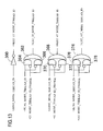
- FIG. 13 is a circuit diagram of the thread ID generation circuit 36
- FIG. 14 is a circuit diagram of the thread switching time selection circuit 34.
- the thread decision circuit 38 is comprised of an AND gate 380, OR gate 382 and 4 AND gates 384-1 to 384-4.
- +WARNING_TO_HUNG_MODE_VALID signal is a signal to indicate that the signal to indicate the hang prevention mode was latched once.
- +MULTI_THREAD_MODE signal is a signal to indicate that the device is running in the multi-thread state.
- the AND gate 380 opens in the hang prevention mode and in the multi-thread state. In other words, the AND gate 380 does not operate if it is not in the hang prevention mode, or if it is not in the multi-thread state (that is, in the single thread state).
- the +HUNG_THREAD_ID_1T_MODE signal is a signal to indicate that the selected thread is changed at every 1 cycle, and indicates a thread selected by the +NEXT_1T_MODE_THREAD_ID signal. This signal to indicate a selected thread is acquired in the circuit depicted in FIG. 12 .
- This combination of signals is provided for 1 cycle, 2 cycles, 4 cycles and 16 cycles, and a thread selected from 4 AND gates 384-1 to 384-4 is input to the AND gate 380 via the OR gate 382, and becomes a hang prevention thread ID in the next cycle.
- the thread ID generation circuit in FIG. 13 is a circuit to determine a thread in the 1 cycle, 2 cycle, 4 cycle and 16 cycle mode. In 1 cycle mode, a thread changes at every cycle, so the inversion circuit 360 inverts the polarity of the +HUNG_MODE_THREAD_ID to indicate the hang prevention thread ID.
- the circuits 362, 364 and 366 in the 2 cycle mode invert the polarity of +HUNG_MODE_THREAD_ID, which indicates the hang prevention thread ID, using the AND gate 366, if +2T_MODE_THREAD_ID_CHANGE, which indicates that 2 cycles have elapsed since the change of the thread, became ON. If +2T_MODE_THREAD_ID_CHANGE is OFF, the circuits 362, 364 and 366 output +HUNG_MODE_THREAD_ID to indicate the hang prevention thread ID from the AND gate 364.
- the OR gate 362 outputs a signal to change the thread if +2T_MODE_THREAD_ID_CHANGE is ON, and a signal not to change the thread if +2T_MODE_THREAD_ID_CHANGE is OFF.
- +4T_MODE_THREAD_ID_CHANGE to indicate that 4 cycles have elapsed
- +16T_MODE_THREAD_ID_CHANGE to indicate that 16 cycles have elapsed is ON by the combination of 2 AND gates 370 and 372 or 376 and 378, and OR gate 368 or 374 respectively, the thread is changed.
- FIG. 14 depicts a thread switching time change circuit.
- +SET_WARNING_TO_HUNG_MODE which is input to the AND gate 342 to indicate the hang prevention mode, is ON, and +WARNING_TO_HUNG_MODE_VALID to indicate that this signal was latched once is OFF
- 1 cycle mode is activated from the AND gate 342 and the OR gate 340 (the hang prevention mode is started).
- the +1T_MODE_TIMER_CHANGE signal to indicate a time to switch to 2 cycle mode is OFF
- +HUNG_THREAD_ID_1T_MODE which indicates the 1 cycle mode, is ON
- the 1 cycle mode is continued from the AND gate 352 by the AND gate 344.
- the +1T_MODE_TIMER_CHANGE signal turns ON to switch to the 2 cycle mode via the AND gate 356, OR gate 354 and AND gate 346.
- each of these circuits has AND gates 353 and 355, OR gate 351 and AND gate 348; or has AND gates 359 and 349, OR gate 357 and AND gate 350.
- a state where an instruction is not completed for a predetermined period is detected during simultaneous multi-thread operation, and it is controlled so that all the reservation stations can execute only a predetermined thread, therefore if an entry that cannot be executed from the reservation station exists, execution of an entry in the thread that cannot be executed can be enabled by stopping the execution of the thread which has been continuously executed.
Landscapes
- Engineering & Computer Science (AREA)
- Software Systems (AREA)
- Theoretical Computer Science (AREA)
- Physics & Mathematics (AREA)
- General Engineering & Computer Science (AREA)
- General Physics & Mathematics (AREA)
- Multimedia (AREA)
- Advance Control (AREA)
- Executing Machine-Instructions (AREA)
Applications Claiming Priority (1)
| Application Number | Priority Date | Filing Date | Title |
|---|---|---|---|
| PCT/JP2007/000653 WO2008155800A1 (fr) | 2007-06-20 | 2007-06-20 | Contrôleur d'exécution d'instructions et procédé de commande d'exécution d'instructions |
Publications (2)
| Publication Number | Publication Date |
|---|---|
| EP2159689A1 true EP2159689A1 (fr) | 2010-03-03 |
| EP2159689A4 EP2159689A4 (fr) | 2011-01-05 |
Family
ID=40155965
Family Applications (1)
| Application Number | Title | Priority Date | Filing Date |
|---|---|---|---|
| EP07790179A Withdrawn EP2159689A4 (fr) | 2007-06-20 | 2007-06-20 | Contrôleur d'exécution d'instructions et procédé de commande d'exécution d'instructions |
Country Status (6)
| Country | Link |
|---|---|
| US (1) | US7958339B2 (fr) |
| EP (1) | EP2159689A4 (fr) |
| JP (1) | JP5104863B2 (fr) |
| KR (1) | KR101100145B1 (fr) |
| CN (1) | CN101681261B (fr) |
| WO (1) | WO2008155800A1 (fr) |
Families Citing this family (31)
| Publication number | Priority date | Publication date | Assignee | Title |
|---|---|---|---|---|
| US11080064B2 (en) | 2014-10-28 | 2021-08-03 | International Business Machines Corporation | Instructions controlling access to shared registers of a multi-threaded processor |
| US9575802B2 (en) | 2014-10-28 | 2017-02-21 | International Business Machines Corporation | Controlling execution of threads in a multi-threaded processor |
| US10108420B2 (en) | 2014-12-14 | 2018-10-23 | Via Alliance Semiconductor Co., Ltd | Mechanism to preclude load replays dependent on long load cycles in an out-of-order processor |
| WO2016097792A1 (fr) | 2014-12-14 | 2016-06-23 | Via Alliance Semiconductor Co., Ltd. | Appareil et procédé permettant d'exclure des répétitions de chargements dépendant d'un accès à un espace mémoire à combinaison d'écriture dans un processeur déclassé |
| US10127046B2 (en) | 2014-12-14 | 2018-11-13 | Via Alliance Semiconductor Co., Ltd. | Mechanism to preclude uncacheable-dependent load replays in out-of-order processor |
| US10175984B2 (en) | 2014-12-14 | 2019-01-08 | Via Alliance Semiconductor Co., Ltd | Apparatus and method to preclude non-core cache-dependent load replays in an out-of-order processor |
| US10108427B2 (en) | 2014-12-14 | 2018-10-23 | Via Alliance Semiconductor Co., Ltd | Mechanism to preclude load replays dependent on fuse array access in an out-of-order processor |
| US10120689B2 (en) | 2014-12-14 | 2018-11-06 | Via Alliance Semiconductor Co., Ltd | Mechanism to preclude load replays dependent on off-die control element access in an out-of-order processor |
| US10228944B2 (en) | 2014-12-14 | 2019-03-12 | Via Alliance Semiconductor Co., Ltd. | Apparatus and method for programmable load replay preclusion |
| US10083038B2 (en) | 2014-12-14 | 2018-09-25 | Via Alliance Semiconductor Co., Ltd | Mechanism to preclude load replays dependent on page walks in an out-of-order processor |
| US10108429B2 (en) | 2014-12-14 | 2018-10-23 | Via Alliance Semiconductor Co., Ltd | Mechanism to preclude shared RAM-dependent load replays in an out-of-order processor |
| WO2016097804A1 (fr) | 2014-12-14 | 2016-06-23 | Via Alliance Semiconductor Co., Ltd. | Mécanisme permettant d'exclure des répétitions de chargements programmables |
| WO2016097815A1 (fr) | 2014-12-14 | 2016-06-23 | Via Alliance Semiconductor Co., Ltd. | Appareil et procédé permettant d'exclure des répétitions de chargements de cycle de bus spécial x86 dans un processeur déclassé |
| KR101837816B1 (ko) | 2014-12-14 | 2018-03-12 | 비아 얼라이언스 세미컨덕터 씨오., 엘티디. | 비순차 프로세서에서 i/o의존 로드 리플레이를 불가능하게 하는 메커니즘 |
| US10108421B2 (en) | 2014-12-14 | 2018-10-23 | Via Alliance Semiconductor Co., Ltd | Mechanism to preclude shared ram-dependent load replays in an out-of-order processor |
| US10146540B2 (en) | 2014-12-14 | 2018-12-04 | Via Alliance Semiconductor Co., Ltd | Apparatus and method to preclude load replays dependent on write combining memory space access in an out-of-order processor |
| WO2016097803A1 (fr) * | 2014-12-14 | 2016-06-23 | Via Alliance Semiconductor Co., Ltd. | Mécanisme permettant d'exclure des répétitions de chargements dépendants ne pouvant être mis en mémoire cache dans un processeur déclassé |
| US10146539B2 (en) | 2014-12-14 | 2018-12-04 | Via Alliance Semiconductor Co., Ltd. | Load replay precluding mechanism |
| US10089112B2 (en) | 2014-12-14 | 2018-10-02 | Via Alliance Semiconductor Co., Ltd | Mechanism to preclude load replays dependent on fuse array access in an out-of-order processor |
| KR101837817B1 (ko) | 2014-12-14 | 2018-03-12 | 비아 얼라이언스 세미컨덕터 씨오., 엘티디. | 비순차 프로세서에서 페이지 워크에 따라 로드 리플레이를 억제하는 메커니즘 |
| US10114646B2 (en) | 2014-12-14 | 2018-10-30 | Via Alliance Semiconductor Co., Ltd | Programmable load replay precluding mechanism |
| KR101822726B1 (ko) | 2014-12-14 | 2018-01-26 | 비아 얼라이언스 세미컨덕터 씨오., 엘티디. | 로드 리플레이를 억제하는 메커니즘 |
| KR101819314B1 (ko) | 2014-12-14 | 2018-01-16 | 비아 얼라이언스 세미컨덕터 씨오., 엘티디. | 비순차 프로세서에서 오프다이 제어 부재 접근에 따라 로드 리플레이를 억제하는 장치 |
| US10088881B2 (en) | 2014-12-14 | 2018-10-02 | Via Alliance Semiconductor Co., Ltd | Mechanism to preclude I/O-dependent load replays in an out-of-order processor |
| US9703359B2 (en) | 2014-12-14 | 2017-07-11 | Via Alliance Semiconductor Co., Ltd. | Power saving mechanism to reduce load replays in out-of-order processor |
| JP6286067B2 (ja) * | 2014-12-14 | 2018-02-28 | ヴィア アライアンス セミコンダクター カンパニー リミテッド | アウトオブオーダープロセッサでの長いロードサイクルに依存するロードリプレイを除外するメカニズム |
| US9804845B2 (en) | 2014-12-14 | 2017-10-31 | Via Alliance Semiconductor Co., Ltd. | Apparatus and method to preclude X86 special bus cycle load replays in an out-of-order processor |
| US10209996B2 (en) | 2014-12-14 | 2019-02-19 | Via Alliance Semiconductor Co., Ltd. | Apparatus and method for programmable load replay preclusion |
| WO2016097790A1 (fr) | 2014-12-14 | 2016-06-23 | Via Alliance Semiconductor Co., Ltd. | Appareil et procédé permettant d'exclure des répétitions de chargements dépendant d'un cache extérieur au cœur dans un processeur déclassé |
| JP6477248B2 (ja) * | 2015-05-22 | 2019-03-06 | 富士通株式会社 | 演算処理装置及び演算処理装置の処理方法 |
| JP7020304B2 (ja) * | 2018-06-07 | 2022-02-16 | 富士通株式会社 | 演算処理装置及び演算処理装置の制御方法 |
Family Cites Families (15)
| Publication number | Priority date | Publication date | Assignee | Title |
|---|---|---|---|---|
| US6658447B2 (en) * | 1997-07-08 | 2003-12-02 | Intel Corporation | Priority based simultaneous multi-threading |
| US6076157A (en) * | 1997-10-23 | 2000-06-13 | International Business Machines Corporation | Method and apparatus to force a thread switch in a multithreaded processor |
| US6212544B1 (en) * | 1997-10-23 | 2001-04-03 | International Business Machines Corporation | Altering thread priorities in a multithreaded processor |
| JP2000010800A (ja) * | 1998-06-19 | 2000-01-14 | Toshiba Corp | 計算機システムに於けるスレッド制御装置、及び同システムに於けるスレッド制御方法 |
| JP3560482B2 (ja) | 1998-12-17 | 2004-09-02 | 富士通株式会社 | 命令制御装置 |
| JP3490005B2 (ja) | 1998-12-17 | 2004-01-26 | 富士通株式会社 | 命令制御装置及びその方法 |
| US6807624B1 (en) * | 1998-12-17 | 2004-10-19 | Fujitsu Limited | Instruction control device and method therefor |
| US6535905B1 (en) * | 1999-04-29 | 2003-03-18 | Intel Corporation | Method and apparatus for thread switching within a multithreaded processor |
| JP3714597B2 (ja) * | 2000-07-03 | 2005-11-09 | 富士重工業株式会社 | 鍛造方法及び鍛造装置 |
| US20050033831A1 (en) * | 2002-10-08 | 2005-02-10 | Abbas Rashid | Advanced processor with a thread aware return address stack optimally used across active threads |
| US6904511B2 (en) | 2002-10-11 | 2005-06-07 | Sandbridge Technologies, Inc. | Method and apparatus for register file port reduction in a multithreaded processor |
| US20040216103A1 (en) * | 2003-04-24 | 2004-10-28 | International Business Machines Corporation | Mechanism for detecting and handling a starvation of a thread in a multithreading processor environment |
| JP4327008B2 (ja) * | 2004-04-21 | 2009-09-09 | 富士通株式会社 | 演算処理装置及び演算処理装置の制御方法 |
| JP4952580B2 (ja) | 2005-04-21 | 2012-06-13 | 富士通株式会社 | プロセッサ装置 |
| JP5028774B2 (ja) | 2005-09-22 | 2012-09-19 | 富士通株式会社 | 演算処理装置,情報処理装置,及びレジスタファイルの制御方法 |
-
2007
- 2007-06-20 JP JP2009520141A patent/JP5104863B2/ja not_active Expired - Fee Related
- 2007-06-20 EP EP07790179A patent/EP2159689A4/fr not_active Withdrawn
- 2007-06-20 KR KR1020097026497A patent/KR101100145B1/ko not_active Expired - Fee Related
- 2007-06-20 CN CN200780053423.8A patent/CN101681261B/zh not_active Expired - Fee Related
- 2007-06-20 WO PCT/JP2007/000653 patent/WO2008155800A1/fr not_active Ceased
-
2009
- 2009-12-07 US US12/591,994 patent/US7958339B2/en not_active Expired - Fee Related
Also Published As
| Publication number | Publication date |
|---|---|
| KR101100145B1 (ko) | 2011-12-29 |
| CN101681261A (zh) | 2010-03-24 |
| JPWO2008155800A1 (ja) | 2010-08-26 |
| US7958339B2 (en) | 2011-06-07 |
| WO2008155800A1 (fr) | 2008-12-24 |
| CN101681261B (zh) | 2014-07-16 |
| US20100095092A1 (en) | 2010-04-15 |
| JP5104863B2 (ja) | 2012-12-19 |
| EP2159689A4 (fr) | 2011-01-05 |
| KR20100009593A (ko) | 2010-01-27 |
Similar Documents
| Publication | Publication Date | Title |
|---|---|---|
| US7958339B2 (en) | Instruction execution control device and instruction execution control method | |
| JP4287799B2 (ja) | プロセッサシステムおよびスレッド切り替え制御方法 | |
| US6542921B1 (en) | Method and apparatus for controlling the processing priority between multiple threads in a multithreaded processor | |
| US20150074353A1 (en) | System and Method for an Asynchronous Processor with Multiple Threading | |
| JP2006260571A (ja) | デュアルスレッドプロセッサ | |
| EP2573673B1 (fr) | Processeur multifilière et procédé de contrôle d'extraction d'instructions pour processeur multifilière | |
| EP2782004B1 (fr) | Procédé et processeur multifils opportunistes | |
| EP1886216B1 (fr) | Controle de pipelines d'execution hors service au moyen de parametres de desalignement | |
| JP2535252B2 (ja) | 並列処理装置 | |
| EP2159691B1 (fr) | Contrôleur d'achèvement d'instruction multifile simultané | |
| US20060259741A1 (en) | Controlling out of order execution pipelines issue tagging | |
| JPWO2008155794A1 (ja) | 情報処理装置 | |
| KR102838225B1 (ko) | 데이터 구조 포기 | |
| JPH09274565A (ja) | 分岐による中断のないパイプライン化されたマイクロプロセッサ及びその動作方法 | |
| KR20180126518A (ko) | 벡터 명령 처리 | |
| EP2159688A1 (fr) | Dispositif de commande d'exécution d'instructions et procédé de commande d'exécution d'instructions | |
| US9965283B2 (en) | Multi-threaded processor interrupting and saving execution states of complex instructions of a first thread to allow execution of an oldest ready instruction of a second thread | |
| US20050160254A1 (en) | Multithread processor architecture for triggered thread switching without any clock cycle loss, without any switching program instruction, and without extending the program instruction format | |
| EP2843543B1 (fr) | Dispositif de traitement arithmétique et procédé de commande d'un tel dispositif | |
| JP6098429B2 (ja) | 演算処理装置及び演算処理装置の制御方法 | |
| JP5573038B2 (ja) | マルチスレッドプロセッサ及びプログラム | |
| JP2001356904A (ja) | プロセッサ |
Legal Events
| Date | Code | Title | Description |
|---|---|---|---|
| PUAI | Public reference made under article 153(3) epc to a published international application that has entered the european phase |
Free format text: ORIGINAL CODE: 0009012 |
|
| 17P | Request for examination filed |
Effective date: 20091216 |
|
| AK | Designated contracting states |
Kind code of ref document: A1 Designated state(s): AT BE BG CH CY CZ DE DK EE ES FI FR GB GR HU IE IS IT LI LT LU LV MC MT NL PL PT RO SE SI SK TR |
|
| AX | Request for extension of the european patent |
Extension state: AL BA HR MK RS |
|
| DAX | Request for extension of the european patent (deleted) | ||
| A4 | Supplementary search report drawn up and despatched |
Effective date: 20101206 |
|
| 17Q | First examination report despatched |
Effective date: 20121008 |
|
| GRAP | Despatch of communication of intention to grant a patent |
Free format text: ORIGINAL CODE: EPIDOSNIGR1 |
|
| INTG | Intention to grant announced |
Effective date: 20150731 |
|
| STAA | Information on the status of an ep patent application or granted ep patent |
Free format text: STATUS: THE APPLICATION IS DEEMED TO BE WITHDRAWN |
|
| 18D | Application deemed to be withdrawn |
Effective date: 20151210 |