EP2159769A2 - Améliorations dans et concernant des systèmes de connexion électriques - Google Patents
Améliorations dans et concernant des systèmes de connexion électriques Download PDFInfo
- Publication number
- EP2159769A2 EP2159769A2 EP09166223A EP09166223A EP2159769A2 EP 2159769 A2 EP2159769 A2 EP 2159769A2 EP 09166223 A EP09166223 A EP 09166223A EP 09166223 A EP09166223 A EP 09166223A EP 2159769 A2 EP2159769 A2 EP 2159769A2
- Authority
- EP
- European Patent Office
- Prior art keywords
- housing
- ceiling
- bezel plate
- fixing
- hole
- Prior art date
- Legal status (The legal status is an assumption and is not a legal conclusion. Google has not performed a legal analysis and makes no representation as to the accuracy of the status listed.)
- Granted
Links
Images
Classifications
-
- H—ELECTRICITY
- H02—GENERATION; CONVERSION OR DISTRIBUTION OF ELECTRIC POWER
- H02G—INSTALLATION OF ELECTRIC CABLES OR LINES, OR OF COMBINED OPTICAL AND ELECTRIC CABLES OR LINES
- H02G3/00—Installations of electric cables or lines or protective tubing therefor in or on buildings, equivalent structures or vehicles
- H02G3/02—Details
- H02G3/08—Distribution boxes; Connection or junction boxes
- H02G3/18—Distribution boxes; Connection or junction boxes providing line outlets
- H02G3/20—Ceiling roses or other lighting sets
-
- G—PHYSICS
- G08—SIGNALLING
- G08B—SIGNALLING SYSTEMS, e.g. PERSONAL CALLING SYSTEMS; ORDER TELEGRAPHS; ALARM SYSTEMS
- G08B17/00—Fire alarms; Alarms responsive to explosion
- G08B17/10—Actuation by presence of smoke or gases, e.g. automatic alarm devices for analysing flowing fluid materials by the use of optical means
-
- G—PHYSICS
- G08—SIGNALLING
- G08B—SIGNALLING SYSTEMS, e.g. PERSONAL CALLING SYSTEMS; ORDER TELEGRAPHS; ALARM SYSTEMS
- G08B17/00—Fire alarms; Alarms responsive to explosion
- G08B17/10—Actuation by presence of smoke or gases, e.g. automatic alarm devices for analysing flowing fluid materials by the use of optical means
- G08B17/11—Actuation by presence of smoke or gases, e.g. automatic alarm devices for analysing flowing fluid materials by the use of optical means using an ionisation chamber for detecting smoke or gas
- G08B17/113—Constructional details
-
- H—ELECTRICITY
- H01—ELECTRIC ELEMENTS
- H01R—ELECTRICALLY-CONDUCTIVE CONNECTIONS; STRUCTURAL ASSOCIATIONS OF A PLURALITY OF MUTUALLY-INSULATED ELECTRICAL CONNECTING ELEMENTS; COUPLING DEVICES; CURRENT COLLECTORS
- H01R13/00—Details of coupling devices of the kinds covered by groups H01R12/70 or H01R24/00 - H01R33/00
- H01R13/73—Means for mounting coupling parts to apparatus or structures, e.g. to a wall
- H01R13/74—Means for mounting coupling parts in openings of a panel
- H01R13/741—Means for mounting coupling parts in openings of a panel using snap fastening means
- H01R13/745—Means for mounting coupling parts in openings of a panel using snap fastening means separate from the housing
-
- H—ELECTRICITY
- H01—ELECTRIC ELEMENTS
- H01R—ELECTRICALLY-CONDUCTIVE CONNECTIONS; STRUCTURAL ASSOCIATIONS OF A PLURALITY OF MUTUALLY-INSULATED ELECTRICAL CONNECTING ELEMENTS; COUPLING DEVICES; CURRENT COLLECTORS
- H01R33/00—Coupling devices specially adapted for supporting apparatus and having one part acting as a holder providing support and electrical connection via a counterpart which is structurally associated with the apparatus, e.g. lamp holders; Separate parts thereof
- H01R33/94—Holders formed as intermediate parts for linking a counter-part to a coupling part
-
- H—ELECTRICITY
- H02—GENERATION; CONVERSION OR DISTRIBUTION OF ELECTRIC POWER
- H02G—INSTALLATION OF ELECTRIC CABLES OR LINES, OR OF COMBINED OPTICAL AND ELECTRIC CABLES OR LINES
- H02G3/00—Installations of electric cables or lines or protective tubing therefor in or on buildings, equivalent structures or vehicles
- H02G3/02—Details
- H02G3/08—Distribution boxes; Connection or junction boxes
- H02G3/14—Fastening of cover or lid to box
Definitions
- the present invention relates to electrical connection systems and finds particular but not exclusive use in electrical systems mounted in ceilings, such as fire or smoke detection systems.
- Prior art smoke detection systems such as those fitted in a commercial or industrial environment, comprise a plurality (often hundreds) of detectors, often daisy-chained together in loops including many tens of units.
- An aim of embodiments of the present invention is to allow quicker, easier installation of a smoke/fire detector system, particularly, but not exclusively, in cases where no suspended ceiling has yet been installed to which the individual sensor heads are to be fitted.
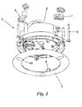
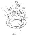
- Figures 1 and 2 show a view of a detector base 1 according to an embodiment of the invention.
- the detector base 1 is housed in a ceiling, connected to one or more other such devices and/or a control system and is arranged to receive an operation unit such as a smoke/fire detector or sounder unit.
- the detector base 1 comprises a housing 2 which is arranged to sit in the ceiling void, normally behind a suspended ceiling tile.
- the housing 2 has a plurality of electrical connectors 4 for coupling the detector base to either one or more other detector bases or terminating at a control panel.
- the electrical connectors in this embodiment take the form of sockets arranged to receive pre-formed cables terminated in complementary plugs. Other forms of electrical connection are possible, including screw terminals, spade connectors or similar.
- the detector base 1 may be used in two distinct situations. As mentioned, the fire/smoke detection system is often the last part, or one of the last parts, of a building's infrastructure to be installed and it is possible that the system has to be installed either before or after the installation of a suspended ceiling, which is also normally concluded late in the process.
- the detector base 1 is provided with a removable bezel plate 3 which couples to the housing 2.
- the detector base 1 can be preassembled with the bezel plate 3 attached to the housing 2 by use of protrusions 5 on the bezel plate 3, which mate with corresponding apertures 6 on the housing.
- the coupling is achieved by inserting protrusions 5 into apertures 6 and then rotating the bezel plate slightly to cause it to lock in position.
- the cabling is drawn out through the hole and connected to the detector base at sockets 4.
- the detector base 1 is then offered up to the hole and the housing 2 penetrates the hole, causing the bezel plate 3 to abut the external surface of the ceiling.
- three fixing wings 7 are provided.
- the fixing wings 7 are rotated inwards and lie within the circumference of the housing 2, allowing the housing to penetrate the hole in the ceiling.
- a screwdriver is inserted through hole 8 in the bezel plate 3 to contact and rotate screw 9.
- the fixing wing 7 is rotated out of its insertion position to lie outside the circumference of the housing 2.
- the fixing wing is caused to travel down the screw thread and thus clamps the ceiling tile between the fixing wing and the bezel plate 3.
- a feature of the bezel plate 3, provided to ensure its correct attachment to the housing 2, is that the screw holes 8 only align with the screws 9 once the bezel has been correctly twisted into position relative to the housing 2. This ensures that the bezel and housing are firmly attached and able to clamp the ceiling properly.
- Cosmetic screw covers 10 are provided to conceal the screw holes 8 in the bezel plate 3.
- the suspended ceiling is not yet fitted, and the smoke and fire detection system must be fitted first. This can pose problems using prior art devices, as is generally only possible to fit them once the ceiling is already in place.
- detector base 1 without fitting the bezel plate 3, it is possible to completely connect the cabling and detector bases required to configure and test the system, and to complete the installation by fitting the bezel plate at a later date.
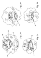
- Figures 3a-3d show this type of installation in more detail.
- a housing 2 which has attached to it an operational unit, such as a sensor head or smoke detector 20.
- Figure 3a also shows the cabling connected to sockets 4, which has been connected previously.
- the basic installation details are similar to that which has been previously defined.
- the main difference is that the housing 2 is already connected and sits inside the ceiling void. To secure it in position, it is withdrawn from the void as shown in Figure 3a , and the bezel plate 3 is attached by inserting protrusions or tags 5 into apertures 6 and twisting the bezel plate to lock it into place.
- the detector base 1 comprising housing 2 and bezel plate 3
- the detector base 1 is inserted into the hole in the ceiling and the installation can continue as previously described. This stage is shown in Figure 3b .
- the bezel plate may be provided with ceiling-engaging projections which are intended to pierce the surface of the ceiling and assist in holding the device in place.
- Figure 3c shows a view, from within the ceiling void, of the housing 2 once securely positioned by fixing wings 7 which are shown contacting the interior surface of the ceiling 11.
- Figure 3d shows a view of the detector base in position with an operational unit 20, such as a fire or smoke detector, attached thereto. This figure also shows the cosmetic screw caps and how they attach to the bezel plate 3.
- the cosmetic screw caps 10 are removed, the screws 9 and rotated, causing the fixing wings to rotate back towards the housing, thus allowing the housing 2 to be removed through the hole in the ceiling.
Landscapes
- General Physics & Mathematics (AREA)
- Chemical & Material Sciences (AREA)
- Analytical Chemistry (AREA)
- Business, Economics & Management (AREA)
- Emergency Management (AREA)
- Physics & Mathematics (AREA)
- Architecture (AREA)
- Civil Engineering (AREA)
- Structural Engineering (AREA)
- Engineering & Computer Science (AREA)
- Fire-Detection Mechanisms (AREA)
- Connector Housings Or Holding Contact Members (AREA)
- Fire Alarms (AREA)
Applications Claiming Priority (1)
| Application Number | Priority Date | Filing Date | Title |
|---|---|---|---|
| GBGB0815640.8A GB0815640D0 (en) | 2008-08-28 | 2008-08-28 | Improvements in and relating to electrical connection systems |
Publications (3)
| Publication Number | Publication Date |
|---|---|
| EP2159769A2 true EP2159769A2 (fr) | 2010-03-03 |
| EP2159769A3 EP2159769A3 (fr) | 2014-12-24 |
| EP2159769B1 EP2159769B1 (fr) | 2016-11-16 |
Family
ID=39865851
Family Applications (1)
| Application Number | Title | Priority Date | Filing Date |
|---|---|---|---|
| EP09166223.9A Active EP2159769B1 (fr) | 2008-08-28 | 2009-07-23 | Améliorations dans et concernant des systèmes de connexion électriques |
Country Status (2)
| Country | Link |
|---|---|
| EP (1) | EP2159769B1 (fr) |
| GB (1) | GB0815640D0 (fr) |
Citations (1)
| Publication number | Priority date | Publication date | Assignee | Title |
|---|---|---|---|---|
| WO2007138340A1 (fr) | 2006-05-27 | 2007-12-06 | Protec Fire Detection Plc | Améliorations dans des systèmes de connexion électrique et en relation à eux |
Family Cites Families (6)
| Publication number | Priority date | Publication date | Assignee | Title |
|---|---|---|---|---|
| CH567822A5 (fr) * | 1974-05-14 | 1975-10-15 | Fawa | |
| EP1191652A1 (fr) * | 1999-05-28 | 2002-03-27 | Koichi Wada | Bati decoratif |
| DE10011905C2 (de) * | 2000-03-11 | 2002-01-17 | Kaiser Gmbh & Co Kg | Hohlkörper für die Elektroinstallation |
| ATE297527T1 (de) * | 2001-03-14 | 2005-06-15 | Acbond Ltd | Verbesserungen mit bezug auf rauchmelder |
| US6780049B1 (en) * | 2003-06-11 | 2004-08-24 | D'angelo Carlo Armond | Ceiling fixture light/fan quick connect and release |
| US7064269B2 (en) * | 2004-11-23 | 2006-06-20 | Smith David W | Quick connect electrical junction box assembly |
-
2008
- 2008-08-28 GB GBGB0815640.8A patent/GB0815640D0/en not_active Ceased
-
2009
- 2009-07-23 EP EP09166223.9A patent/EP2159769B1/fr active Active
Patent Citations (1)
| Publication number | Priority date | Publication date | Assignee | Title |
|---|---|---|---|---|
| WO2007138340A1 (fr) | 2006-05-27 | 2007-12-06 | Protec Fire Detection Plc | Améliorations dans des systèmes de connexion électrique et en relation à eux |
Also Published As
| Publication number | Publication date |
|---|---|
| EP2159769B1 (fr) | 2016-11-16 |
| EP2159769A3 (fr) | 2014-12-24 |
| GB0815640D0 (en) | 2008-10-08 |
Similar Documents
| Publication | Publication Date | Title |
|---|---|---|
| AU2011309880B2 (en) | Mounting unit | |
| EP3637569B1 (fr) | Installation d'un disjoncteur enfichable | |
| US20200158348A1 (en) | Range hood installation system | |
| CN101378161A (zh) | 用于电气部件的模块化壁盒单元 | |
| US9338922B2 (en) | Rack adapter apparatus and method | |
| US20190347880A1 (en) | Access credential reader connector | |
| US9793659B2 (en) | Suspended ceiling mounting bracket for connector installation | |
| US20170125943A1 (en) | Locking and extraction device for an electrical connector | |
| US9639112B2 (en) | Mounting assembly for electronic throttle control assembly | |
| CA2984552A1 (fr) | Interconnexion mecanique d'appareil d'eclairage au moyen d'un raccord rotatif et de mecanismes caches | |
| WO2016180002A1 (fr) | Appareil de montage de dispositif | |
| EP2159769B1 (fr) | Améliorations dans et concernant des systèmes de connexion électriques | |
| EP2022021B1 (fr) | Améliorations relatives aux systèmes de connexion électrique | |
| AU2017314914B2 (en) | Tool-less replaceable gas sensor module | |
| CN110913652A (zh) | 一种可导轨及螺栓安装的io模块 | |
| US8664939B2 (en) | Utility meter cover with interlocking bidirectional tab | |
| JP4232540B2 (ja) | フリープラン対応配線システム | |
| KR20250167538A (ko) | 화면 표시 케이블 결선 상태 자동 점검 장치 | |
| US20210210905A1 (en) | Automotive electrical connector features for robotic installation | |
| JP4356391B2 (ja) | ジョイントボックス | |
| EP2051346B1 (fr) | Ensemble de matériels d'installation, interface de matériels d'installation, élément encastré et procédé pour assembler un ensemble de matériels d'installation | |
| WO2016114703A1 (fr) | Plaque arrière | |
| JPH0685915U (ja) | センサ端末機器の取付装置 | |
| Bartolome et al. | Diagnostic and Remote Maintenance of Distributed Control Systems Using Freeware Solutions | |
| JPH04126486U (ja) | 埋め込み型スピーカ装置 |
Legal Events
| Date | Code | Title | Description |
|---|---|---|---|
| PUAI | Public reference made under article 153(3) epc to a published international application that has entered the european phase |
Free format text: ORIGINAL CODE: 0009012 |
|
| 17P | Request for examination filed |
Effective date: 20090723 |
|
| AK | Designated contracting states |
Kind code of ref document: A2 Designated state(s): AT BE BG CH CY CZ DE DK EE ES FI FR GB GR HR HU IE IS IT LI LT LU LV MC MK MT NL NO PL PT RO SE SI SK SM TR |
|
| REG | Reference to a national code |
Ref country code: DE Ref legal event code: R079 Ref document number: 602009042392 Country of ref document: DE Free format text: PREVIOUS MAIN CLASS: G08B0017100000 Ipc: G08B0017000000 |
|
| PUAL | Search report despatched |
Free format text: ORIGINAL CODE: 0009013 |
|
| AK | Designated contracting states |
Kind code of ref document: A3 Designated state(s): AT BE BG CH CY CZ DE DK EE ES FI FR GB GR HR HU IE IS IT LI LT LU LV MC MK MT NL NO PL PT RO SE SI SK SM TR |
|
| RIC1 | Information provided on ipc code assigned before grant |
Ipc: H02G 3/20 20060101ALI20141120BHEP Ipc: H01R 33/94 20060101ALN20141120BHEP Ipc: H01R 13/74 20060101ALI20141120BHEP Ipc: H02G 3/14 20060101ALN20141120BHEP Ipc: G08B 17/00 20060101AFI20141120BHEP |
|
| 17Q | First examination report despatched |
Effective date: 20151221 |
|
| GRAP | Despatch of communication of intention to grant a patent |
Free format text: ORIGINAL CODE: EPIDOSNIGR1 |
|
| INTG | Intention to grant announced |
Effective date: 20160610 |
|
| GRAS | Grant fee paid |
Free format text: ORIGINAL CODE: EPIDOSNIGR3 |
|
| GRAA | (expected) grant |
Free format text: ORIGINAL CODE: 0009210 |
|
| AK | Designated contracting states |
Kind code of ref document: B1 Designated state(s): AT BE BG CH CY CZ DE DK EE ES FI FR GB GR HR HU IE IS IT LI LT LU LV MC MK MT NL NO PL PT RO SE SI SK SM TR |
|
| REG | Reference to a national code |
Ref country code: GB Ref legal event code: FG4D |
|
| REG | Reference to a national code |
Ref country code: CH Ref legal event code: EP |
|
| REG | Reference to a national code |
Ref country code: IE Ref legal event code: FG4D |
|
| REG | Reference to a national code |
Ref country code: AT Ref legal event code: REF Ref document number: 846564 Country of ref document: AT Kind code of ref document: T Effective date: 20161215 |
|
| REG | Reference to a national code |
Ref country code: DE Ref legal event code: R096 Ref document number: 602009042392 Country of ref document: DE |
|
| PG25 | Lapsed in a contracting state [announced via postgrant information from national office to epo] |
Ref country code: LV Free format text: LAPSE BECAUSE OF FAILURE TO SUBMIT A TRANSLATION OF THE DESCRIPTION OR TO PAY THE FEE WITHIN THE PRESCRIBED TIME-LIMIT Effective date: 20161116 |
|
| REG | Reference to a national code |
Ref country code: NL Ref legal event code: MP Effective date: 20161116 |
|
| REG | Reference to a national code |
Ref country code: LT Ref legal event code: MG4D |
|
| REG | Reference to a national code |
Ref country code: AT Ref legal event code: MK05 Ref document number: 846564 Country of ref document: AT Kind code of ref document: T Effective date: 20161116 |
|
| PG25 | Lapsed in a contracting state [announced via postgrant information from national office to epo] |
Ref country code: NO Free format text: LAPSE BECAUSE OF FAILURE TO SUBMIT A TRANSLATION OF THE DESCRIPTION OR TO PAY THE FEE WITHIN THE PRESCRIBED TIME-LIMIT Effective date: 20170216 Ref country code: LT Free format text: LAPSE BECAUSE OF FAILURE TO SUBMIT A TRANSLATION OF THE DESCRIPTION OR TO PAY THE FEE WITHIN THE PRESCRIBED TIME-LIMIT Effective date: 20161116 Ref country code: NL Free format text: LAPSE BECAUSE OF FAILURE TO SUBMIT A TRANSLATION OF THE DESCRIPTION OR TO PAY THE FEE WITHIN THE PRESCRIBED TIME-LIMIT Effective date: 20161116 Ref country code: GR Free format text: LAPSE BECAUSE OF FAILURE TO SUBMIT A TRANSLATION OF THE DESCRIPTION OR TO PAY THE FEE WITHIN THE PRESCRIBED TIME-LIMIT Effective date: 20170217 Ref country code: SE Free format text: LAPSE BECAUSE OF FAILURE TO SUBMIT A TRANSLATION OF THE DESCRIPTION OR TO PAY THE FEE WITHIN THE PRESCRIBED TIME-LIMIT Effective date: 20161116 |
|
| PG25 | Lapsed in a contracting state [announced via postgrant information from national office to epo] |
Ref country code: FI Free format text: LAPSE BECAUSE OF FAILURE TO SUBMIT A TRANSLATION OF THE DESCRIPTION OR TO PAY THE FEE WITHIN THE PRESCRIBED TIME-LIMIT Effective date: 20161116 Ref country code: PT Free format text: LAPSE BECAUSE OF FAILURE TO SUBMIT A TRANSLATION OF THE DESCRIPTION OR TO PAY THE FEE WITHIN THE PRESCRIBED TIME-LIMIT Effective date: 20170316 Ref country code: ES Free format text: LAPSE BECAUSE OF FAILURE TO SUBMIT A TRANSLATION OF THE DESCRIPTION OR TO PAY THE FEE WITHIN THE PRESCRIBED TIME-LIMIT Effective date: 20161116 Ref country code: PL Free format text: LAPSE BECAUSE OF FAILURE TO SUBMIT A TRANSLATION OF THE DESCRIPTION OR TO PAY THE FEE WITHIN THE PRESCRIBED TIME-LIMIT Effective date: 20161116 Ref country code: AT Free format text: LAPSE BECAUSE OF FAILURE TO SUBMIT A TRANSLATION OF THE DESCRIPTION OR TO PAY THE FEE WITHIN THE PRESCRIBED TIME-LIMIT Effective date: 20161116 Ref country code: HR Free format text: LAPSE BECAUSE OF FAILURE TO SUBMIT A TRANSLATION OF THE DESCRIPTION OR TO PAY THE FEE WITHIN THE PRESCRIBED TIME-LIMIT Effective date: 20161116 |
|
| PG25 | Lapsed in a contracting state [announced via postgrant information from national office to epo] |
Ref country code: DK Free format text: LAPSE BECAUSE OF FAILURE TO SUBMIT A TRANSLATION OF THE DESCRIPTION OR TO PAY THE FEE WITHIN THE PRESCRIBED TIME-LIMIT Effective date: 20161116 Ref country code: RO Free format text: LAPSE BECAUSE OF FAILURE TO SUBMIT A TRANSLATION OF THE DESCRIPTION OR TO PAY THE FEE WITHIN THE PRESCRIBED TIME-LIMIT Effective date: 20161116 Ref country code: EE Free format text: LAPSE BECAUSE OF FAILURE TO SUBMIT A TRANSLATION OF THE DESCRIPTION OR TO PAY THE FEE WITHIN THE PRESCRIBED TIME-LIMIT Effective date: 20161116 Ref country code: CZ Free format text: LAPSE BECAUSE OF FAILURE TO SUBMIT A TRANSLATION OF THE DESCRIPTION OR TO PAY THE FEE WITHIN THE PRESCRIBED TIME-LIMIT Effective date: 20161116 Ref country code: SK Free format text: LAPSE BECAUSE OF FAILURE TO SUBMIT A TRANSLATION OF THE DESCRIPTION OR TO PAY THE FEE WITHIN THE PRESCRIBED TIME-LIMIT Effective date: 20161116 |
|
| REG | Reference to a national code |
Ref country code: DE Ref legal event code: R097 Ref document number: 602009042392 Country of ref document: DE |
|
| PG25 | Lapsed in a contracting state [announced via postgrant information from national office to epo] |
Ref country code: SM Free format text: LAPSE BECAUSE OF FAILURE TO SUBMIT A TRANSLATION OF THE DESCRIPTION OR TO PAY THE FEE WITHIN THE PRESCRIBED TIME-LIMIT Effective date: 20161116 Ref country code: BG Free format text: LAPSE BECAUSE OF FAILURE TO SUBMIT A TRANSLATION OF THE DESCRIPTION OR TO PAY THE FEE WITHIN THE PRESCRIBED TIME-LIMIT Effective date: 20170216 Ref country code: IT Free format text: LAPSE BECAUSE OF FAILURE TO SUBMIT A TRANSLATION OF THE DESCRIPTION OR TO PAY THE FEE WITHIN THE PRESCRIBED TIME-LIMIT Effective date: 20161116 Ref country code: BE Free format text: LAPSE BECAUSE OF FAILURE TO SUBMIT A TRANSLATION OF THE DESCRIPTION OR TO PAY THE FEE WITHIN THE PRESCRIBED TIME-LIMIT Effective date: 20161116 |
|
| PLBE | No opposition filed within time limit |
Free format text: ORIGINAL CODE: 0009261 |
|
| STAA | Information on the status of an ep patent application or granted ep patent |
Free format text: STATUS: NO OPPOSITION FILED WITHIN TIME LIMIT |
|
| 26N | No opposition filed |
Effective date: 20170817 |
|
| PG25 | Lapsed in a contracting state [announced via postgrant information from national office to epo] |
Ref country code: SI Free format text: LAPSE BECAUSE OF FAILURE TO SUBMIT A TRANSLATION OF THE DESCRIPTION OR TO PAY THE FEE WITHIN THE PRESCRIBED TIME-LIMIT Effective date: 20161116 |
|
| REG | Reference to a national code |
Ref country code: DE Ref legal event code: R119 Ref document number: 602009042392 Country of ref document: DE |
|
| REG | Reference to a national code |
Ref country code: CH Ref legal event code: PL |
|
| REG | Reference to a national code |
Ref country code: IE Ref legal event code: MM4A |
|
| REG | Reference to a national code |
Ref country code: FR Ref legal event code: ST Effective date: 20180330 |
|
| PG25 | Lapsed in a contracting state [announced via postgrant information from national office to epo] |
Ref country code: DE Free format text: LAPSE BECAUSE OF NON-PAYMENT OF DUE FEES Effective date: 20180201 Ref country code: CH Free format text: LAPSE BECAUSE OF NON-PAYMENT OF DUE FEES Effective date: 20170731 Ref country code: IE Free format text: LAPSE BECAUSE OF NON-PAYMENT OF DUE FEES Effective date: 20170723 Ref country code: LI Free format text: LAPSE BECAUSE OF NON-PAYMENT OF DUE FEES Effective date: 20170731 |
|
| PG25 | Lapsed in a contracting state [announced via postgrant information from national office to epo] |
Ref country code: FR Free format text: LAPSE BECAUSE OF NON-PAYMENT OF DUE FEES Effective date: 20170731 |
|
| PG25 | Lapsed in a contracting state [announced via postgrant information from national office to epo] |
Ref country code: LU Free format text: LAPSE BECAUSE OF NON-PAYMENT OF DUE FEES Effective date: 20170723 |
|
| PG25 | Lapsed in a contracting state [announced via postgrant information from national office to epo] |
Ref country code: MT Free format text: LAPSE BECAUSE OF NON-PAYMENT OF DUE FEES Effective date: 20170723 |
|
| PG25 | Lapsed in a contracting state [announced via postgrant information from national office to epo] |
Ref country code: MC Free format text: LAPSE BECAUSE OF FAILURE TO SUBMIT A TRANSLATION OF THE DESCRIPTION OR TO PAY THE FEE WITHIN THE PRESCRIBED TIME-LIMIT Effective date: 20161116 Ref country code: HU Free format text: LAPSE BECAUSE OF FAILURE TO SUBMIT A TRANSLATION OF THE DESCRIPTION OR TO PAY THE FEE WITHIN THE PRESCRIBED TIME-LIMIT; INVALID AB INITIO Effective date: 20090723 |
|
| PG25 | Lapsed in a contracting state [announced via postgrant information from national office to epo] |
Ref country code: CY Free format text: LAPSE BECAUSE OF NON-PAYMENT OF DUE FEES Effective date: 20161116 |
|
| PG25 | Lapsed in a contracting state [announced via postgrant information from national office to epo] |
Ref country code: MK Free format text: LAPSE BECAUSE OF FAILURE TO SUBMIT A TRANSLATION OF THE DESCRIPTION OR TO PAY THE FEE WITHIN THE PRESCRIBED TIME-LIMIT Effective date: 20161116 |
|
| PG25 | Lapsed in a contracting state [announced via postgrant information from national office to epo] |
Ref country code: TR Free format text: LAPSE BECAUSE OF FAILURE TO SUBMIT A TRANSLATION OF THE DESCRIPTION OR TO PAY THE FEE WITHIN THE PRESCRIBED TIME-LIMIT Effective date: 20161116 |
|
| PG25 | Lapsed in a contracting state [announced via postgrant information from national office to epo] |
Ref country code: IS Free format text: LAPSE BECAUSE OF FAILURE TO SUBMIT A TRANSLATION OF THE DESCRIPTION OR TO PAY THE FEE WITHIN THE PRESCRIBED TIME-LIMIT Effective date: 20170316 |
|
| PGFP | Annual fee paid to national office [announced via postgrant information from national office to epo] |
Ref country code: GB Payment date: 20250724 Year of fee payment: 17 |