EP2159883A1 - Douille de connecteur - Google Patents
Douille de connecteur Download PDFInfo
- Publication number
- EP2159883A1 EP2159883A1 EP09010633A EP09010633A EP2159883A1 EP 2159883 A1 EP2159883 A1 EP 2159883A1 EP 09010633 A EP09010633 A EP 09010633A EP 09010633 A EP09010633 A EP 09010633A EP 2159883 A1 EP2159883 A1 EP 2159883A1
- Authority
- EP
- European Patent Office
- Prior art keywords
- connector
- sleeve
- connector socket
- embossing tool
- passage
- Prior art date
- Legal status (The legal status is an assumption and is not a legal conclusion. Google has not performed a legal analysis and makes no representation as to the accuracy of the status listed.)
- Granted
Links
Images


Classifications
-
- H—ELECTRICITY
- H01—ELECTRIC ELEMENTS
- H01R—ELECTRICALLY-CONDUCTIVE CONNECTIONS; STRUCTURAL ASSOCIATIONS OF A PLURALITY OF MUTUALLY-INSULATED ELECTRICAL CONNECTING ELEMENTS; COUPLING DEVICES; CURRENT COLLECTORS
- H01R13/00—Details of coupling devices of the kinds covered by groups H01R12/70 or H01R24/00 - H01R33/00
- H01R13/02—Contact members
- H01R13/15—Pins, blades or sockets having separate spring member for producing or increasing contact pressure
- H01R13/187—Pins, blades or sockets having separate spring member for producing or increasing contact pressure with spring member in the socket
-
- H—ELECTRICITY
- H01—ELECTRIC ELEMENTS
- H01R—ELECTRICALLY-CONDUCTIVE CONNECTIONS; STRUCTURAL ASSOCIATIONS OF A PLURALITY OF MUTUALLY-INSULATED ELECTRICAL CONNECTING ELEMENTS; COUPLING DEVICES; CURRENT COLLECTORS
- H01R11/00—Individual connecting elements providing two or more spaced connecting locations for conductive members which are, or may be, thereby interconnected, e.g. end pieces for wires or cables supported by the wire or cable and having means for facilitating electrical connection to some other wire, terminal, or conductive member, blocks of binding posts
- H01R11/11—End pieces or tapping pieces for wires, supported by the wire and for facilitating electrical connection to some other wire, terminal or conductive member
- H01R11/28—End pieces consisting of a ferrule or sleeve
-
- H—ELECTRICITY
- H01—ELECTRIC ELEMENTS
- H01R—ELECTRICALLY-CONDUCTIVE CONNECTIONS; STRUCTURAL ASSOCIATIONS OF A PLURALITY OF MUTUALLY-INSULATED ELECTRICAL CONNECTING ELEMENTS; COUPLING DEVICES; CURRENT COLLECTORS
- H01R4/00—Electrically-conductive connections between two or more conductive members in direct contact, i.e. touching one another; Means for effecting or maintaining such contact; Electrically-conductive connections having two or more spaced connecting locations for conductors and using contact members penetrating insulation
- H01R4/10—Electrically-conductive connections between two or more conductive members in direct contact, i.e. touching one another; Means for effecting or maintaining such contact; Electrically-conductive connections having two or more spaced connecting locations for conductors and using contact members penetrating insulation effected solely by twisting, wrapping, bending, crimping, or other permanent deformation
-
- H—ELECTRICITY
- H01—ELECTRIC ELEMENTS
- H01R—ELECTRICALLY-CONDUCTIVE CONNECTIONS; STRUCTURAL ASSOCIATIONS OF A PLURALITY OF MUTUALLY-INSULATED ELECTRICAL CONNECTING ELEMENTS; COUPLING DEVICES; CURRENT COLLECTORS
- H01R43/00—Apparatus or processes specially adapted for manufacturing, assembling, maintaining, or repairing of line connectors or current collectors or for joining electric conductors
- H01R43/16—Apparatus or processes specially adapted for manufacturing, assembling, maintaining, or repairing of line connectors or current collectors or for joining electric conductors for manufacturing contact members, e.g. by punching and by bending
-
- H—ELECTRICITY
- H01—ELECTRIC ELEMENTS
- H01R—ELECTRICALLY-CONDUCTIVE CONNECTIONS; STRUCTURAL ASSOCIATIONS OF A PLURALITY OF MUTUALLY-INSULATED ELECTRICAL CONNECTING ELEMENTS; COUPLING DEVICES; CURRENT COLLECTORS
- H01R4/00—Electrically-conductive connections between two or more conductive members in direct contact, i.e. touching one another; Means for effecting or maintaining such contact; Electrically-conductive connections having two or more spaced connecting locations for conductors and using contact members penetrating insulation
- H01R4/10—Electrically-conductive connections between two or more conductive members in direct contact, i.e. touching one another; Means for effecting or maintaining such contact; Electrically-conductive connections having two or more spaced connecting locations for conductors and using contact members penetrating insulation effected solely by twisting, wrapping, bending, crimping, or other permanent deformation
- H01R4/18—Electrically-conductive connections between two or more conductive members in direct contact, i.e. touching one another; Means for effecting or maintaining such contact; Electrically-conductive connections having two or more spaced connecting locations for conductors and using contact members penetrating insulation effected solely by twisting, wrapping, bending, crimping, or other permanent deformation by crimping
- H01R4/20—Electrically-conductive connections between two or more conductive members in direct contact, i.e. touching one another; Means for effecting or maintaining such contact; Electrically-conductive connections having two or more spaced connecting locations for conductors and using contact members penetrating insulation effected solely by twisting, wrapping, bending, crimping, or other permanent deformation by crimping using a crimping sleeve
-
- H—ELECTRICITY
- H01—ELECTRIC ELEMENTS
- H01R—ELECTRICALLY-CONDUCTIVE CONNECTIONS; STRUCTURAL ASSOCIATIONS OF A PLURALITY OF MUTUALLY-INSULATED ELECTRICAL CONNECTING ELEMENTS; COUPLING DEVICES; CURRENT COLLECTORS
- H01R43/00—Apparatus or processes specially adapted for manufacturing, assembling, maintaining, or repairing of line connectors or current collectors or for joining electric conductors
- H01R43/04—Apparatus or processes specially adapted for manufacturing, assembling, maintaining, or repairing of line connectors or current collectors or for joining electric conductors for forming connections by deformation, e.g. crimping tool
Definitions
- the invention relates to an electrical connector socket equipped with a LamellenANDgitter, and a crimp connector. Furthermore, the invention relates to a method for producing a connector socket with crimp connector, in particular a connector socket with a cylindrical connector socket sleeve.
- the WO00 / 70713 also describes a female contact, which is formed from a connector sleeve with a crimp terminal, in turn, a radially symmetrical contact sleeve is received, which in turn is itself incorporated in a tubular sleeve.
- the lamella contact grid consists of an additional tubular sleeve.
- FIGS. 9 and 10 show, for example in FIGS. 9 and 10, the structure of a connector socket with a crimp connector fixedly connected thereto.
- a disadvantage in particular has the effect that at high currents at least only a relatively small area, the transition region from the outer sleeve to the actual crimp connection can contribute to the current carrying capacity.
- the DE 10 2005 057 893 already discloses an electrical contact element for electrically contacting an electrical conductor with a bolt, in particular a ground connection bolt.
- this disclosure teaches a person skilled in the art to form a crimp contact element such that the contact region is provided with a central opening and formed from a folded metal strip folded such that the central openings of the lower and upper metal strips are superposed on each other.
- a central opening for a ground connection bolt is formed with which the electrical contact element can engage.
- To reinforce is located around the central opening a circular embossing, such that the elevations of these embossments after folding lie one above the other and touch each other. This serves to reinforce the electrical contact element.
- a cylindrical contact element is permanently connected to the electrical connector.
- the contact element has a pot-like press-in area with a corresponding opening for the cylindrical contact element to be fitted therein.
- the cylindrical contact element either can not be inserted into the passage opening at all or just loosely inserted and a firm connection is not guaranteed.
- Object of the present invention is therefore to overcome in particular the aforementioned disadvantages and such a connector socket or a female connector sleeve with a crimp connector simpler, cheaper to manufacture and in particular to sufficiently eliminate the problems of tolerances, so that a secure contact system can be produced.
- the object of the present invention resides in the fact that a crimping connector with production-related tolerances has a suitable connection region which allows it to be permanently and firmly connected to a particularly cylindrical connector sleeve, even in the presence of system-related and production-related tolerances.
- Another object of the present invention is to provide such a connector socket, which has a sufficiently high current carrying capacity and thus over such an embodiment that the available for the current contact cross section from the transition of the lamella contact grid to the cable is not comparable to those in the prior art mentioned embodiments is weakened.
- Another object of the present invention is therefore to provide a production method which overcomes said disadvantages and at the same time remains cost-effective to carry out.
- This object is achieved in that a folded crimp is provided with a targeted hole fit.
- This hole fit (also referred to as a passage) is formed in the simplest embodiment as a hole in a folded surface.
- the diameter of the passage will be referred to as Dc below.
- Dc target is the nominal diameter of the draft.
- Dc the actually produced diameter is described.
- the outer diameter of the cylindrical connector bushing sleeve is referred to below as Dh, in which case Dh, Soll describes the desired nominal diameter, while Dh, Ist describes the actually produced outer diameter.
- the diameter Dc, target to the diameter Dh, target is tuned in such a way that a defined slot S between Dh, Soll and Dc, target is formed when the crimp is slipped over the tubular connector socket sleeve and is mounted on this.
- ⁇ X there is a mounting clearance ⁇ X, which mathematically results from the difference difference between the different diameters Dh, Soll and Dc, Soll.
- the tolerance field ⁇ X results from the maximum actual diameter values Dh, Ist and Dc, Ist.
- Dh, Ist and Dc, Ist there is a tolerance field between 0 and ⁇ X, where 0 represents the state in which Dc, Soll and Dh, Soll equal to Dc, Ist and Dh, Ist represents. It then turns out to be exactly the desired clearance between the outer diameter of the female connector sleeve and the passage of the Crimpverbinders to form an infinitesimal small gap S.
- the crimp connector is made by folding a sheet on at least one fold edge so that the thickness of the Crimpverbinderflansches is sufficiently thick and compact, so that there is sufficient contact with the connector sleeve connector.
- connection between the crimp connector and the connector sleeve is made by an embossing tool, while the area around the passage is mechanically deformed such that a U-shaped annular groove forms on the top and bottom of the passage flange and one of the U-legs extends outwards on the Outer jacket of the connector sleeve.
- the embossing tool may be formed so that a notch or a groove is formed, which corresponds in its cross section to a U with equilateral legs.
- one of the legs and that formed under the plastic deformation applied to the connector socket sleeve leg can be formed either with lesser height as the thickness of the fürzugsflansches or even with greater height, depending on how large to choose the contact surface of the fürzugflansches with the connector socket sleeve is.
- the passage flange has been formed to form a single folding of a sheet.
- the cable terminal side of the crimp connector may preferably be formed to form a substantially annular cable receiving space.
- a half-open crimp connection area could also be formed on the crimp connector.
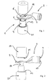
- Fig. 1 to Fig. 4 the manufacturing method of the connector socket 1 according to the invention is shown in more detail.
- a connector socket 1 is provided with an inserted into the connector socket 1 LamellenANDgitter 2 and a crimp connector 3.
- the connector socket 1 is mounted on a embossing tool lower part 21, wherein the connector socket 1 is mounted with its LamellenANDgitter 2 on the attached to the embossing tool part 21 pin 22.
- the pin 22 is fixedly connected to the embossing tool lower part 21 to form an annular gap 23.
- the connector socket 1 is slipped so far over the pin 22 and moved along the lamella contact grid 2 along this, until the bottom of the connector socket 1 rests on the underside of the embossing tool base 21.
- the connector socket 1 can be moved in any suitable position along the pin 22, as it holds the connector socket 1 with the lamella contact grid 2 by clamping. This is accomplished by the fact that the contact blades of the lamella contact grid 2 resiliently abut against the pin 22.
- an inner stop in the annular gap 23 may be arranged on the embossing tool lower part 21 in order to determine the exact position of the connector socket 1.
- the crimp connector 3 is now formed by folding a plastically deformable metal or compressing a pipe section, in which the sheet is folded or pressed against each other at least once so that a fürzugflansch Structure 8 is formed, in which a hole-shaped passage 6 is punched.
- the hole-shaped passage 6 is given a diameter Dc which is slightly larger than the outside diameter Dh of the connector socket 1.
- the crimp connector 3 is formed with a crimp connection 9, preferably a cable receiving space 10, in which the sheet is punched by deformation, bent and formed into the desired shape.
- the pull-through flange 6 can also be formed to form two tube outer halves pressed against one another, wherein a piece of pipe of length L is partially pressed together at an end region such that a pull-through flange 8 and a crimping connection 9 result.
- the crimp connector 3 is now pushed with its passage 6 over the outer diameter of the connector socket 1 and by means of a stamping tool upper part 20, and this in Fig. 3 is shown plastically deformed.
- the embossing tool upper part 20 and the embossing tool lower part 21 each have a ring portion 24, 25 which protrudes from the tool.
- the intervening passage flange 8 of the crimp connector 3 is plastically and mechanically deformed such that one groove 11 is formed at the top and bottom, each with a leg 12, which the crimp connector 3 with its passage flange. 8 firmly attached to the connector socket sleeve 4.
- the connector socket 1 produced by this method now has a fixed connection to the crimp connector 3 independently of the outside diameter Dh of the connector sleeve 4.
- Fig. 6 shows that the position of the pull-through flange 8 with respect to the connector sleeve sleeve 4 can be arranged at any point.
- Fig. 7 shows a leg 12 adjacent to the outer jacket of the connector sleeve 4 under clamping receiving this sleeve.
Landscapes
- Engineering & Computer Science (AREA)
- Manufacturing & Machinery (AREA)
- Connector Housings Or Holding Contact Members (AREA)
- Manufacturing Of Electrical Connectors (AREA)
- Connections Effected By Soldering, Adhesion, Or Permanent Deformation (AREA)
- Details Of Connecting Devices For Male And Female Coupling (AREA)
Applications Claiming Priority (1)
| Application Number | Priority Date | Filing Date | Title |
|---|---|---|---|
| DE102008039786A DE102008039786B3 (de) | 2008-08-26 | 2008-08-26 | Steckverbinderbuchse |
Publications (2)
| Publication Number | Publication Date |
|---|---|
| EP2159883A1 true EP2159883A1 (fr) | 2010-03-03 |
| EP2159883B1 EP2159883B1 (fr) | 2011-10-19 |
Family
ID=41168577
Family Applications (1)
| Application Number | Title | Priority Date | Filing Date |
|---|---|---|---|
| EP09010633A Active EP2159883B1 (fr) | 2008-08-26 | 2009-08-19 | Douille de connecteur |
Country Status (3)
| Country | Link |
|---|---|
| EP (1) | EP2159883B1 (fr) |
| AT (1) | ATE529924T1 (fr) |
| DE (1) | DE102008039786B3 (fr) |
Cited By (3)
| Publication number | Priority date | Publication date | Assignee | Title |
|---|---|---|---|---|
| CN103069653A (zh) * | 2010-08-19 | 2013-04-24 | 富加宜汽车控股公司 | 电源端子 |
| WO2017101662A1 (fr) * | 2015-12-15 | 2017-06-22 | 德尔福中央电气(上海)有限公司 | Borne de connexion à angle droit pour courant élevé |
| CN107017496A (zh) * | 2017-05-26 | 2017-08-04 | 赵沙 | 一种用于电连接系统的内曲面插簧端子 |
Families Citing this family (3)
| Publication number | Priority date | Publication date | Assignee | Title |
|---|---|---|---|---|
| DE202015106944U1 (de) * | 2015-12-18 | 2016-01-14 | Amphenol-Tuchel Electronics Gmbh | Kontaktanordnung |
| DE102017110527A1 (de) | 2017-05-15 | 2018-11-15 | Valeo Siemens Eautomotive Germany Gmbh | Klemmenbrett zum Befestigen von elektrischen Leitungen und Verfahren zum Befestigen von elektrischen Leitungen an einem Klemmenbrett |
| DE102018124086A1 (de) | 2018-09-28 | 2020-04-02 | Amphenol Tuchel Industrial GmbH | Pressverbindung |
Citations (7)
| Publication number | Priority date | Publication date | Assignee | Title |
|---|---|---|---|---|
| US5667413A (en) | 1995-11-13 | 1997-09-16 | Alcoa Fujikura Ltd. | Socket-type electrical connector |
| WO2000070713A2 (fr) | 1999-05-12 | 2000-11-23 | K & K Stamping Company | Connecteur electrique et son procede de fabrication |
| US20020187686A1 (en) | 2000-09-15 | 2002-12-12 | Weiping Zhao | Electrical terminal socket assembly including T shaped sealed connectors |
| DE202004005593U1 (de) * | 2004-04-08 | 2005-08-18 | Kondryn, Rolf-Dieter | Elektrische Kupplungsvorrichtung |
| DE102005057893A1 (de) | 2005-12-02 | 2007-06-14 | Stocko Contact Gmbh & Co. Kg | Elektrisches Kontaktelement |
| DE102006012337B3 (de) | 2006-03-17 | 2007-11-29 | Amphenol-Tuchel Electronics Gmbh | Elektrischer Steckverbinder |
| DE202008005394U1 (de) * | 2008-04-18 | 2008-07-31 | Amphenol-Tuchel Electronics Gmbh | Hochstromleiterplattensteckverbinder |
Family Cites Families (2)
| Publication number | Priority date | Publication date | Assignee | Title |
|---|---|---|---|---|
| US4720157A (en) * | 1986-10-30 | 1988-01-19 | General Motors Corporation | Electrical connector having resilient contact means |
| FR2842656B1 (fr) * | 2002-07-16 | 2005-03-11 | Valeo Climatisation | Connecteur electrique, notamment pour dispositif de chauffage de vehicule |
-
2008
- 2008-08-26 DE DE102008039786A patent/DE102008039786B3/de not_active Expired - Fee Related
-
2009
- 2009-08-19 EP EP09010633A patent/EP2159883B1/fr active Active
- 2009-08-19 AT AT09010633T patent/ATE529924T1/de active
Patent Citations (7)
| Publication number | Priority date | Publication date | Assignee | Title |
|---|---|---|---|---|
| US5667413A (en) | 1995-11-13 | 1997-09-16 | Alcoa Fujikura Ltd. | Socket-type electrical connector |
| WO2000070713A2 (fr) | 1999-05-12 | 2000-11-23 | K & K Stamping Company | Connecteur electrique et son procede de fabrication |
| US20020187686A1 (en) | 2000-09-15 | 2002-12-12 | Weiping Zhao | Electrical terminal socket assembly including T shaped sealed connectors |
| DE202004005593U1 (de) * | 2004-04-08 | 2005-08-18 | Kondryn, Rolf-Dieter | Elektrische Kupplungsvorrichtung |
| DE102005057893A1 (de) | 2005-12-02 | 2007-06-14 | Stocko Contact Gmbh & Co. Kg | Elektrisches Kontaktelement |
| DE102006012337B3 (de) | 2006-03-17 | 2007-11-29 | Amphenol-Tuchel Electronics Gmbh | Elektrischer Steckverbinder |
| DE202008005394U1 (de) * | 2008-04-18 | 2008-07-31 | Amphenol-Tuchel Electronics Gmbh | Hochstromleiterplattensteckverbinder |
Cited By (6)
| Publication number | Priority date | Publication date | Assignee | Title |
|---|---|---|---|---|
| CN103069653A (zh) * | 2010-08-19 | 2013-04-24 | 富加宜汽车控股公司 | 电源端子 |
| CN103069653B (zh) * | 2010-08-19 | 2016-10-26 | 富加宜汽车控股公司 | 电源端子 |
| WO2017101662A1 (fr) * | 2015-12-15 | 2017-06-22 | 德尔福中央电气(上海)有限公司 | Borne de connexion à angle droit pour courant élevé |
| CN106887756A (zh) * | 2015-12-15 | 2017-06-23 | 德尔福中央电气(上海)有限公司 | 一种高载流直角连接端子 |
| CN106887756B (zh) * | 2015-12-15 | 2018-09-25 | 安波福中央电气(上海)有限公司 | 一种高载流直角连接端子 |
| CN107017496A (zh) * | 2017-05-26 | 2017-08-04 | 赵沙 | 一种用于电连接系统的内曲面插簧端子 |
Also Published As
| Publication number | Publication date |
|---|---|
| EP2159883B1 (fr) | 2011-10-19 |
| ATE529924T1 (de) | 2011-11-15 |
| DE102008039786B3 (de) | 2010-04-01 |
Similar Documents
| Publication | Publication Date | Title |
|---|---|---|
| EP1997191B1 (fr) | Connecteur Radsok à enclenchement | |
| EP0919074B1 (fr) | Connexion electrique | |
| DE10041516B4 (de) | Elektrische Anschlußvorrichtung für hohe Ströme | |
| EP2159883B1 (fr) | Douille de connecteur | |
| EP2061119B1 (fr) | Elément de contact et procédé de fabrcation | |
| EP4449564A1 (fr) | Élément de contact en deux parties pour raccordements de fiches électriques et procédé de production dudit élément de contact | |
| WO2016113089A1 (fr) | Contact à insérer comprenant une zone d'insertion enroulable | |
| EP0232808A2 (fr) | Connecteur électrique à fiches pour câble coaxial et procédé de fabrication | |
| EP0397150A2 (fr) | Unité de broche et douille de contact | |
| DE3237159C1 (de) | Kontaktelement fuer elektrische Steckverbindungen und Verfahren zur Herstellung von derartigen Kontaktelementen | |
| DE69624309T2 (de) | Elektrisches Anschlussteil mit Verriegelungszunge | |
| DE10202637C1 (de) | Steckverbinder | |
| EP2028725B1 (fr) | Pont de connecteur enfichable à broche creuse | |
| EP1503463B1 (fr) | Douille d'encastrement | |
| DE102012201124A1 (de) | Bandförmiges Kontaktelement, insbesondere für Hochvolt-Steckverbindungen | |
| EP4443665A1 (fr) | Connecteur coaxial multi-parties configurable de façon variable par rapport à la géométrie d'interface | |
| DE102005063286A1 (de) | Kontaktbuchse für einen Steckerstift | |
| DE102013201689B4 (de) | Schirmgehäuse | |
| DE102020133001B3 (de) | Einpress-Gerätesteckverbinder zum Pressfügen mit einem Metallgehäuse | |
| DE102021120465A1 (de) | Elektrisches Kontaktelement und Verfahren zum Anschließen eines Leiters an das elektrische Kontaktelement | |
| EP4690382A1 (fr) | Connecteur enfichable blindé à contact de mise à la terre et son procédé d'assemblage | |
| EP3503305A1 (fr) | Isolateur, connecteur, utilisation d'un manchon de contact dans un isolateur et utilisation d'un manchon de contact en tant qu'élément de fixation | |
| DE102018010189A1 (de) | Stator für elne elektrische Maschine, insbesondere elnen Elektromotor, und elektrische Maschine, vorzugsweise Elektromotor | |
| DE202007014059U1 (de) | HF-Steckverbinder |
Legal Events
| Date | Code | Title | Description |
|---|---|---|---|
| PUAI | Public reference made under article 153(3) epc to a published international application that has entered the european phase |
Free format text: ORIGINAL CODE: 0009012 |
|
| AK | Designated contracting states |
Kind code of ref document: A1 Designated state(s): AT BE BG CH CY CZ DE DK EE ES FI FR GB GR HR HU IE IS IT LI LT LU LV MC MK MT NL NO PL PT RO SE SI SK SM TR |
|
| AX | Request for extension of the european patent |
Extension state: AL BA RS |
|
| 17P | Request for examination filed |
Effective date: 20100903 |
|
| 17Q | First examination report despatched |
Effective date: 20101123 |
|
| GRAP | Despatch of communication of intention to grant a patent |
Free format text: ORIGINAL CODE: EPIDOSNIGR1 |
|
| GRAS | Grant fee paid |
Free format text: ORIGINAL CODE: EPIDOSNIGR3 |
|
| GRAA | (expected) grant |
Free format text: ORIGINAL CODE: 0009210 |
|
| AK | Designated contracting states |
Kind code of ref document: B1 Designated state(s): AT BE BG CH CY CZ DE DK EE ES FI FR GB GR HR HU IE IS IT LI LT LU LV MC MK MT NL NO PL PT RO SE SI SK SM TR |
|
| AX | Request for extension of the european patent |
Extension state: AL BA RS |
|
| REG | Reference to a national code |
Ref country code: GB Ref legal event code: FG4D Free format text: NOT ENGLISH |
|
| REG | Reference to a national code |
Ref country code: CH Ref legal event code: EP |
|
| REG | Reference to a national code |
Ref country code: IE Ref legal event code: FG4D |
|
| REG | Reference to a national code |
Ref country code: DE Ref legal event code: R096 Ref document number: 502009001617 Country of ref document: DE Effective date: 20111208 |
|
| REG | Reference to a national code |
Ref country code: SE Ref legal event code: TRGR |
|
| REG | Reference to a national code |
Ref country code: NL Ref legal event code: VDEP Effective date: 20111019 |
|
| LTIE | Lt: invalidation of european patent or patent extension |
Effective date: 20111019 |
|
| PG25 | Lapsed in a contracting state [announced via postgrant information from national office to epo] |
Ref country code: LT Free format text: LAPSE BECAUSE OF FAILURE TO SUBMIT A TRANSLATION OF THE DESCRIPTION OR TO PAY THE FEE WITHIN THE PRESCRIBED TIME-LIMIT Effective date: 20111019 Ref country code: IS Free format text: LAPSE BECAUSE OF FAILURE TO SUBMIT A TRANSLATION OF THE DESCRIPTION OR TO PAY THE FEE WITHIN THE PRESCRIBED TIME-LIMIT Effective date: 20120219 Ref country code: NO Free format text: LAPSE BECAUSE OF FAILURE TO SUBMIT A TRANSLATION OF THE DESCRIPTION OR TO PAY THE FEE WITHIN THE PRESCRIBED TIME-LIMIT Effective date: 20120119 |
|
| REG | Reference to a national code |
Ref country code: IE Ref legal event code: FD4D |
|
| PG25 | Lapsed in a contracting state [announced via postgrant information from national office to epo] |
Ref country code: SI Free format text: LAPSE BECAUSE OF FAILURE TO SUBMIT A TRANSLATION OF THE DESCRIPTION OR TO PAY THE FEE WITHIN THE PRESCRIBED TIME-LIMIT Effective date: 20111019 Ref country code: PT Free format text: LAPSE BECAUSE OF FAILURE TO SUBMIT A TRANSLATION OF THE DESCRIPTION OR TO PAY THE FEE WITHIN THE PRESCRIBED TIME-LIMIT Effective date: 20120220 Ref country code: NL Free format text: LAPSE BECAUSE OF FAILURE TO SUBMIT A TRANSLATION OF THE DESCRIPTION OR TO PAY THE FEE WITHIN THE PRESCRIBED TIME-LIMIT Effective date: 20111019 Ref country code: GR Free format text: LAPSE BECAUSE OF FAILURE TO SUBMIT A TRANSLATION OF THE DESCRIPTION OR TO PAY THE FEE WITHIN THE PRESCRIBED TIME-LIMIT Effective date: 20120120 Ref country code: LV Free format text: LAPSE BECAUSE OF FAILURE TO SUBMIT A TRANSLATION OF THE DESCRIPTION OR TO PAY THE FEE WITHIN THE PRESCRIBED TIME-LIMIT Effective date: 20111019 Ref country code: HR Free format text: LAPSE BECAUSE OF FAILURE TO SUBMIT A TRANSLATION OF THE DESCRIPTION OR TO PAY THE FEE WITHIN THE PRESCRIBED TIME-LIMIT Effective date: 20111019 |
|
| PG25 | Lapsed in a contracting state [announced via postgrant information from national office to epo] |
Ref country code: CY Free format text: LAPSE BECAUSE OF FAILURE TO SUBMIT A TRANSLATION OF THE DESCRIPTION OR TO PAY THE FEE WITHIN THE PRESCRIBED TIME-LIMIT Effective date: 20111019 |
|
| PG25 | Lapsed in a contracting state [announced via postgrant information from national office to epo] |
Ref country code: EE Free format text: LAPSE BECAUSE OF FAILURE TO SUBMIT A TRANSLATION OF THE DESCRIPTION OR TO PAY THE FEE WITHIN THE PRESCRIBED TIME-LIMIT Effective date: 20111019 Ref country code: SK Free format text: LAPSE BECAUSE OF FAILURE TO SUBMIT A TRANSLATION OF THE DESCRIPTION OR TO PAY THE FEE WITHIN THE PRESCRIBED TIME-LIMIT Effective date: 20111019 Ref country code: BG Free format text: LAPSE BECAUSE OF FAILURE TO SUBMIT A TRANSLATION OF THE DESCRIPTION OR TO PAY THE FEE WITHIN THE PRESCRIBED TIME-LIMIT Effective date: 20120119 Ref country code: DK Free format text: LAPSE BECAUSE OF FAILURE TO SUBMIT A TRANSLATION OF THE DESCRIPTION OR TO PAY THE FEE WITHIN THE PRESCRIBED TIME-LIMIT Effective date: 20111019 Ref country code: IE Free format text: LAPSE BECAUSE OF FAILURE TO SUBMIT A TRANSLATION OF THE DESCRIPTION OR TO PAY THE FEE WITHIN THE PRESCRIBED TIME-LIMIT Effective date: 20111019 |
|
| PLBE | No opposition filed within time limit |
Free format text: ORIGINAL CODE: 0009261 |
|
| STAA | Information on the status of an ep patent application or granted ep patent |
Free format text: STATUS: NO OPPOSITION FILED WITHIN TIME LIMIT |
|
| PG25 | Lapsed in a contracting state [announced via postgrant information from national office to epo] |
Ref country code: PL Free format text: LAPSE BECAUSE OF FAILURE TO SUBMIT A TRANSLATION OF THE DESCRIPTION OR TO PAY THE FEE WITHIN THE PRESCRIBED TIME-LIMIT Effective date: 20111019 Ref country code: RO Free format text: LAPSE BECAUSE OF FAILURE TO SUBMIT A TRANSLATION OF THE DESCRIPTION OR TO PAY THE FEE WITHIN THE PRESCRIBED TIME-LIMIT Effective date: 20111019 |
|
| 26N | No opposition filed |
Effective date: 20120720 |
|
| REG | Reference to a national code |
Ref country code: DE Ref legal event code: R097 Ref document number: 502009001617 Country of ref document: DE Effective date: 20120720 |
|
| BERE | Be: lapsed |
Owner name: AMPHENOL-TUCHEL ELECTRONICS G.M.B.H. Effective date: 20120831 |
|
| PG25 | Lapsed in a contracting state [announced via postgrant information from national office to epo] |
Ref country code: MC Free format text: LAPSE BECAUSE OF NON-PAYMENT OF DUE FEES Effective date: 20120831 |
|
| PG25 | Lapsed in a contracting state [announced via postgrant information from national office to epo] |
Ref country code: ES Free format text: LAPSE BECAUSE OF FAILURE TO SUBMIT A TRANSLATION OF THE DESCRIPTION OR TO PAY THE FEE WITHIN THE PRESCRIBED TIME-LIMIT Effective date: 20120130 |
|
| PG25 | Lapsed in a contracting state [announced via postgrant information from national office to epo] |
Ref country code: BE Free format text: LAPSE BECAUSE OF NON-PAYMENT OF DUE FEES Effective date: 20120831 |
|
| PG25 | Lapsed in a contracting state [announced via postgrant information from national office to epo] |
Ref country code: FI Free format text: LAPSE BECAUSE OF FAILURE TO SUBMIT A TRANSLATION OF THE DESCRIPTION OR TO PAY THE FEE WITHIN THE PRESCRIBED TIME-LIMIT Effective date: 20111019 |
|
| PG25 | Lapsed in a contracting state [announced via postgrant information from national office to epo] |
Ref country code: MT Free format text: LAPSE BECAUSE OF FAILURE TO SUBMIT A TRANSLATION OF THE DESCRIPTION OR TO PAY THE FEE WITHIN THE PRESCRIBED TIME-LIMIT Effective date: 20111019 |
|
| REG | Reference to a national code |
Ref country code: CH Ref legal event code: PL |
|
| GBPC | Gb: european patent ceased through non-payment of renewal fee |
Effective date: 20130819 |
|
| PG25 | Lapsed in a contracting state [announced via postgrant information from national office to epo] |
Ref country code: TR Free format text: LAPSE BECAUSE OF FAILURE TO SUBMIT A TRANSLATION OF THE DESCRIPTION OR TO PAY THE FEE WITHIN THE PRESCRIBED TIME-LIMIT Effective date: 20111019 Ref country code: LI Free format text: LAPSE BECAUSE OF NON-PAYMENT OF DUE FEES Effective date: 20130831 Ref country code: CH Free format text: LAPSE BECAUSE OF NON-PAYMENT OF DUE FEES Effective date: 20130831 |
|
| PG25 | Lapsed in a contracting state [announced via postgrant information from national office to epo] |
Ref country code: SM Free format text: LAPSE BECAUSE OF FAILURE TO SUBMIT A TRANSLATION OF THE DESCRIPTION OR TO PAY THE FEE WITHIN THE PRESCRIBED TIME-LIMIT Effective date: 20111019 Ref country code: LU Free format text: LAPSE BECAUSE OF NON-PAYMENT OF DUE FEES Effective date: 20120819 |
|
| PG25 | Lapsed in a contracting state [announced via postgrant information from national office to epo] |
Ref country code: GB Free format text: LAPSE BECAUSE OF NON-PAYMENT OF DUE FEES Effective date: 20130819 Ref country code: HU Free format text: LAPSE BECAUSE OF FAILURE TO SUBMIT A TRANSLATION OF THE DESCRIPTION OR TO PAY THE FEE WITHIN THE PRESCRIBED TIME-LIMIT Effective date: 20090819 |
|
| PG25 | Lapsed in a contracting state [announced via postgrant information from national office to epo] |
Ref country code: MK Free format text: LAPSE BECAUSE OF FAILURE TO SUBMIT A TRANSLATION OF THE DESCRIPTION OR TO PAY THE FEE WITHIN THE PRESCRIBED TIME-LIMIT Effective date: 20111019 |
|
| REG | Reference to a national code |
Ref country code: AT Ref legal event code: MM01 Ref document number: 529924 Country of ref document: AT Kind code of ref document: T Effective date: 20140819 |
|
| PG25 | Lapsed in a contracting state [announced via postgrant information from national office to epo] |
Ref country code: AT Free format text: LAPSE BECAUSE OF NON-PAYMENT OF DUE FEES Effective date: 20140819 |
|
| REG | Reference to a national code |
Ref country code: FR Ref legal event code: PLFP Year of fee payment: 8 |
|
| REG | Reference to a national code |
Ref country code: FR Ref legal event code: PLFP Year of fee payment: 9 |
|
| REG | Reference to a national code |
Ref country code: FR Ref legal event code: PLFP Year of fee payment: 10 |
|
| PGFP | Annual fee paid to national office [announced via postgrant information from national office to epo] |
Ref country code: SE Payment date: 20190826 Year of fee payment: 11 Ref country code: CZ Payment date: 20190808 Year of fee payment: 11 |
|
| REG | Reference to a national code |
Ref country code: SE Ref legal event code: EUG |
|
| PG25 | Lapsed in a contracting state [announced via postgrant information from national office to epo] |
Ref country code: CZ Free format text: LAPSE BECAUSE OF NON-PAYMENT OF DUE FEES Effective date: 20200819 |
|
| PG25 | Lapsed in a contracting state [announced via postgrant information from national office to epo] |
Ref country code: SE Free format text: LAPSE BECAUSE OF NON-PAYMENT OF DUE FEES Effective date: 20200820 |
|
| P01 | Opt-out of the competence of the unified patent court (upc) registered |
Effective date: 20230613 |
|
| PGFP | Annual fee paid to national office [announced via postgrant information from national office to epo] |
Ref country code: DE Payment date: 20240819 Year of fee payment: 16 |
|
| PGFP | Annual fee paid to national office [announced via postgrant information from national office to epo] |
Ref country code: FR Payment date: 20240821 Year of fee payment: 16 |
|
| PGFP | Annual fee paid to national office [announced via postgrant information from national office to epo] |
Ref country code: IT Payment date: 20240830 Year of fee payment: 16 |
|
| REG | Reference to a national code |
Ref country code: DE Ref legal event code: R119 Ref document number: 502009001617 Country of ref document: DE |