EP2161202A1 - Stérilisation par rayonnement d'électrons pour récipients - Google Patents
Stérilisation par rayonnement d'électrons pour récipients Download PDFInfo
- Publication number
- EP2161202A1 EP2161202A1 EP09168082A EP09168082A EP2161202A1 EP 2161202 A1 EP2161202 A1 EP 2161202A1 EP 09168082 A EP09168082 A EP 09168082A EP 09168082 A EP09168082 A EP 09168082A EP 2161202 A1 EP2161202 A1 EP 2161202A1
- Authority
- EP
- European Patent Office
- Prior art keywords
- container
- treatment head
- radiation
- movement
- containers
- Prior art date
- Legal status (The legal status is an assumption and is not a legal conclusion. Google has not performed a legal analysis and makes no representation as to the accuracy of the status listed.)
- Granted
Links
Images


Classifications
-
- A—HUMAN NECESSITIES
- A61—MEDICAL OR VETERINARY SCIENCE; HYGIENE
- A61L—METHODS OR APPARATUS FOR STERILISING MATERIALS OR OBJECTS IN GENERAL; DISINFECTION, STERILISATION OR DEODORISATION OF AIR; CHEMICAL ASPECTS OF BANDAGES, DRESSINGS, ABSORBENT PADS OR SURGICAL ARTICLES; MATERIALS FOR BANDAGES, DRESSINGS, ABSORBENT PADS OR SURGICAL ARTICLES
- A61L2/00—Disinfection or sterilisation of materials or objects, in general; Accessories therefor
- A61L2/02—Disinfection or sterilisation of materials or objects, in general; Accessories therefor using physical processes
- A61L2/08—Radiation
- A61L2/087—Particle radiation, e.g. electron-beam, alpha or beta radiation
-
- A—HUMAN NECESSITIES
- A61—MEDICAL OR VETERINARY SCIENCE; HYGIENE
- A61L—METHODS OR APPARATUS FOR STERILISING MATERIALS OR OBJECTS IN GENERAL; DISINFECTION, STERILISATION OR DEODORISATION OF AIR; CHEMICAL ASPECTS OF BANDAGES, DRESSINGS, ABSORBENT PADS OR SURGICAL ARTICLES; MATERIALS FOR BANDAGES, DRESSINGS, ABSORBENT PADS OR SURGICAL ARTICLES
- A61L2/00—Disinfection or sterilisation of materials or objects, in general; Accessories therefor
- A61L2/02—Disinfection or sterilisation of materials or objects, in general; Accessories therefor using physical processes
- A61L2/08—Radiation
- A61L2/082—X-rays
-
- A—HUMAN NECESSITIES
- A61—MEDICAL OR VETERINARY SCIENCE; HYGIENE
- A61L—METHODS OR APPARATUS FOR STERILISING MATERIALS OR OBJECTS IN GENERAL; DISINFECTION, STERILISATION OR DEODORISATION OF AIR; CHEMICAL ASPECTS OF BANDAGES, DRESSINGS, ABSORBENT PADS OR SURGICAL ARTICLES; MATERIALS FOR BANDAGES, DRESSINGS, ABSORBENT PADS OR SURGICAL ARTICLES
- A61L2/00—Disinfection or sterilisation of materials or objects, in general; Accessories therefor
- A61L2/24—Apparatus using programmed or automatic operation
-
- B—PERFORMING OPERATIONS; TRANSPORTING
- B65—CONVEYING; PACKING; STORING; HANDLING THIN OR FILAMENTARY MATERIAL
- B65B—MACHINES, APPARATUS OR DEVICES FOR, OR METHODS OF, PACKAGING ARTICLES OR MATERIALS; UNPACKING
- B65B55/00—Preserving, protecting or purifying packages or package contents in association with packaging
- B65B55/02—Sterilising, e.g. of complete packages
- B65B55/04—Sterilising wrappers or receptacles prior to, or during, packaging
- B65B55/08—Sterilising wrappers or receptacles prior to, or during, packaging by irradiation
-
- B—PERFORMING OPERATIONS; TRANSPORTING
- B67—OPENING, CLOSING OR CLEANING BOTTLES, JARS OR SIMILAR CONTAINERS; LIQUID HANDLING
- B67C—CLEANING, FILLING WITH LIQUIDS OR SEMILIQUIDS, OR EMPTYING, OF BOTTLES, JARS, CANS, CASKS, BARRELS, OR SIMILAR CONTAINERS, NOT OTHERWISE PROVIDED FOR; FUNNELS
- B67C7/00—Concurrent cleaning, filling, and closing of bottles; Processes or devices for at least two of these operations
- B67C7/0073—Sterilising, aseptic filling and closing
-
- A—HUMAN NECESSITIES
- A61—MEDICAL OR VETERINARY SCIENCE; HYGIENE
- A61L—METHODS OR APPARATUS FOR STERILISING MATERIALS OR OBJECTS IN GENERAL; DISINFECTION, STERILISATION OR DEODORISATION OF AIR; CHEMICAL ASPECTS OF BANDAGES, DRESSINGS, ABSORBENT PADS OR SURGICAL ARTICLES; MATERIALS FOR BANDAGES, DRESSINGS, ABSORBENT PADS OR SURGICAL ARTICLES
- A61L2/00—Disinfection or sterilisation of materials or objects, in general; Accessories therefor
- A61L2/02—Disinfection or sterilisation of materials or objects, in general; Accessories therefor using physical processes
- A61L2/08—Radiation
- A61L2/10—Ultraviolet [UV] radiation
-
- A—HUMAN NECESSITIES
- A61—MEDICAL OR VETERINARY SCIENCE; HYGIENE
- A61L—METHODS OR APPARATUS FOR STERILISING MATERIALS OR OBJECTS IN GENERAL; DISINFECTION, STERILISATION OR DEODORISATION OF AIR; CHEMICAL ASPECTS OF BANDAGES, DRESSINGS, ABSORBENT PADS OR SURGICAL ARTICLES; MATERIALS FOR BANDAGES, DRESSINGS, ABSORBENT PADS OR SURGICAL ARTICLES
- A61L2103/00—Materials or objects being the target of disinfection or sterilisation
- A61L2103/23—Containers other than laboratory or medical, e.g. bottles or mail
-
- A—HUMAN NECESSITIES
- A61—MEDICAL OR VETERINARY SCIENCE; HYGIENE
- A61L—METHODS OR APPARATUS FOR STERILISING MATERIALS OR OBJECTS IN GENERAL; DISINFECTION, STERILISATION OR DEODORISATION OF AIR; CHEMICAL ASPECTS OF BANDAGES, DRESSINGS, ABSORBENT PADS OR SURGICAL ARTICLES; MATERIALS FOR BANDAGES, DRESSINGS, ABSORBENT PADS OR SURGICAL ARTICLES
- A61L2202/00—Aspects relating to methods or apparatus for disinfecting or sterilising materials or objects
- A61L2202/10—Apparatus features
- A61L2202/14—Means for controlling sterilisation processes, data processing, presentation and storage means, e.g. sensors, controllers, programs
-
- B—PERFORMING OPERATIONS; TRANSPORTING
- B29—WORKING OF PLASTICS; WORKING OF SUBSTANCES IN A PLASTIC STATE IN GENERAL
- B29C—SHAPING OR JOINING OF PLASTICS; SHAPING OF MATERIAL IN A PLASTIC STATE, NOT OTHERWISE PROVIDED FOR; AFTER-TREATMENT OF THE SHAPED PRODUCTS, e.g. REPAIRING
- B29C49/00—Blow-moulding, i.e. blowing a preform or parison to a desired shape within a mould; Apparatus therefor
- B29C49/42—Component parts, details or accessories; Auxiliary operations
- B29C49/42403—Purging or cleaning the blow-moulding apparatus
- B29C49/42405—Sterilizing
Definitions
- the present invention relates to a device and a method for sterilizing containers, and more particularly to a method and a device for sterilizing containers by means of electron beams.
- a treatment head is guided into the interior of the container to be sterilized and the treatment head emits radiation inside the container for a predetermined period of time, the container at least temporarily over the treatment head in a longitudinal direction of the container during the predetermined period moved at a relative speed of movement becomes.
- the relative speed of movement of the treatment head located inside the container varies during the predetermined period of time and is controlled in dependence on an inner profile of the container.
- the invention proposes to control the speed of movement of the treatment head relative to the container and thus also the speed of movement of the point at which the said radiation emerges, depending on a profile of the container.
- a variation of the movement speed is understood to be a variation of the movement speed in a specific movement direction, and in particular not a change of sign of the movement speed.
- the treatment head rests and in contrast the container moves in its longitudinal direction. It would also be possible for the treatment head to be moved in a longitudinal direction of the container or else for both the container and the treatment head to move.
- the emission of radiation and the movement in the longitudinal direction preferably take place simultaneously.
- the movement it would also be possible for the movement to take place piecemeal and radiation to be emitted in each case in the breaks.
- At least one parameter is controlled which is characteristic of a radiation power related to the inner surface.
- the power delivered by the treatment head instead of the movement speed, for example via a change in the acceleration voltage in the case of electron emitters.
- a reverse voltage could also be used.
- the treatment head emits charge carriers.
- the treatment head or else another element can have an electron emission source, as well as an accelerating device which accelerates these electrons toward an exit window. With the help of these exiting electrons, the sterilization of Be bachelornisinnenwandungen is effected.
- the movement is controlled by a controller based on data stored by a storage device, which data is characteristic of cross-sections of the container in the longitudinal direction of the container.
- a storage device which data is characteristic of cross-sections of the container in the longitudinal direction of the container.
- this relative movement between the treatment head and the container is programmed via predetermined driving profiles. It is possible to create an entire driving profile for the entire irradiation process and to disassemble this preferably into individual curve segments. In this case, the individual strokes of the container different lifting speeds and possibly also accelerations can be assigned. This division is advantageous in order to obtain a better adaptation to the geometry of the container.
- the movement of the treatment head is controlled in dependence on a diameter of the container. It should be noted that in particular from the treatment head exiting electrons have a certain range or lose a certain proportion of their energy over the distance traveled. In particular, in areas of large diameter of the container, it is therefore necessary that the exposure time is correspondingly longer to compensate for the correspondingly lower energy of the electrons.
- the movement of the treatment head is also controlled in dependence on an angle at which the inner wall of the container extends with respect to the longitudinal direction of the container. For example, in the mouth region of a container, a container section widening from top to bottom is often provided, which is difficult to reach from the exiting electron beam. Accordingly, the speed of movement should also be reduced in these areas.
- the movement is particularly preferably controlled on the basis of a programmed driving profile.
- This Driving profile can be determined based on empirical data for corresponding containers, but it would also be possible to determine this driving profile due to parameters of the container, such as the curvature and the cross section.
- the container itself is moved in its longitudinal direction and thus particularly preferably the treatment head or the jet finger held constant in height.
- a support device may be provided, on which in turn a clamp is arranged, which moves the container itself and in its longitudinal direction up or down.
- the driving profile is determined by guiding a treatment head and the interior of a container or a reference container and the treatment head emits radiation inside the container, wherein the container relative to the treatment head during the emission of the radiation in a longitudinal direction of the container is moved and a variety of characteristic data are recorded, which are characteristic of a incident on an inner wall of the container radiation.
- a reference dose is thus determined, which the treatment head applies to the inner wall of the container. It is also possible here for the emission of the electron radiation to occur simultaneously with the movement, or else for the emission and the movement to alternate at least in part.
- a material is applied to the inner wall of the container, which reacts to the radiation emitted into the treatment head radiation and thus allows conclusions about the intensity of the radiation.
- a dose measurement with the aid of an irradiated measuring film, this measuring film being attached to the inner wall of the container.
- the dose distribution in the treated containers can be determined.
- These measuring strips are discolored depending on the dose rate and can be evaluated with a dose measuring device.
- the measuring film is laminated by a corresponding plastic carrier in order to simulate in this way, the effects that occur inside the container wall.
- a dye can be applied to the measuring film. Under the influence of the radiation, the film changes in proportion to the amount of energy absorbed in certain shades. These shades can then be read out with a dose measuring device and thus indicate which dose was applied, for example, in kilogray (kGy).
- a driving profile for the internal sterilization of containers is determined, wherein a treatment head is guided into the interior of the container and the treatment head inside the container radiation directed to an inner wall of the container, wherein the container relative to the treatment head, preferably during the Emission of the radiation is moved in a longitudinal direction of the container.
- a multiplicity of data is recorded, which are characteristic of a radiation impinging on an inner wall of the container.
- this measuring method is also possible to carry out this measuring method independently of the actual working method described above.
- a multiplicity of containers are measured with the described measuring method and the data of these containers are stored in a database which can be used in the later working method.
- the present invention is further directed to a device for sterilizing containers, which device has a treatment head, which is designed such that it can be guided in an inner space of a container to be sterilized.
- this treatment head has a radiation source which emits radiation
- the device has a movement device which moves the container relative to the treatment head in a longitudinal direction of the container at a predetermined speed of movement, while the treatment head at least temporarily emits radiation.
- the device has a control device, which this relative movement speed of the treatment head located inside the container varies and controls in dependence on an inner profile of the container.
- a treatment head which can be introduced through an orifice into the container, wherein this orifice has a smaller cross-section than, for example, a base body of the container.
- the movement device may be a drive, but in particular but not exclusively to a linear motor, which moves the container in response to a predetermined driving profile.
- the radiation source emits charge carriers and in particular electrons.
- the radiation source emits another type of radiation, such as X-radiation, UV radiation, or the like.
- the basic concept of this invention can also be applied to these other types of radiation.
- the device has a memory device in which a characteristic for the movement of the treatment head driving profile is stored.
- this driving profile may result from empirical data determined for a particular type of bottle.
- the driving profile results at least in part from theoretical considerations, which take into account, for example, the cross-section of a container and also the angle of inclination of Be Strukturniswandung.
- the device has an image recording device, which is an image a container to be sterilized receives.
- the data of this image acquisition can be used for the speed control.
- an image processing software compares this image with a plurality of images for stored containers.
- a corresponding driving profile can be loaded and, during operation, the movement of the treatment head can be controlled on the basis of this driving profile.
- the device has a plurality of treatment heads, which are arranged one behind the other on a transport device. It is possible that both bottle holders such as gripping elements, as well as the treatment heads are arranged on the same transport device and thus moved synchronously to each other.
- the containers are moved during their sterilization, for example on a transport carousel, on which the corresponding treatment heads are moved along. In this way, a high throughput of containers can be sterilized in succession.
- such a device can be designed both as a rotary and as a linear unit. It is possible that the entire device is housed in a treatment room, which serves both the internal and the external sterilization of containers and in particular of PET containers by electron radiation.
- the sterilization unit itself can also be integrated in a stretch blow molding machine or in a filling unit or arranged as a stand-alone unit. The latter variant offers the advantage that existing lines can possibly be retrofitted.
- the integration into a stretch blow molding machine or into a filling device offers the advantage that in this way the costs for the overall production can be reduced.
- the containers are passed over stars, for example stars in neck handling to the sterilization unit, where they are moved by means of a linear lifting movement over the treatment head or beam finger.
- a compact electron beam unit with a beam finger Preferably serves as a beam generator, a compact electron beam unit with a beam finger, which, as mentioned above, is dimensioned such that it can dive into the bottle to apply the electron cloud with the least possible energy to the inner surface of the containers.
- a rotary arrangement it would be possible that appropriate transformers or power supplies for the electron gun run on a carousel, whereby the supply of high voltage is simplified.
- the possibility of improved surface treatment or sterilization for particularly complex shaped beverage containers by electron beams can be realized by the combination of electronic and mechanical components. In this way, in spite of the three-dimensional expansion of the container tears, the most homogeneous possible dose distribution on the inner surface of the containers can be achieved.
- the substrate to be treated or the container is preferably moved relative to a fixed radiation source, wherein, as mentioned above, the movement sequence is adapted to the applied dose rate.
- Fig. 1 shows a schematic representation of a device 1 according to the invention, which may be part of a system for treating containers.
- the reference numeral 10 refers to a container having an inner wall 10a, which is to be sterilized by means of e-marked electrons.
- the reference numeral 5 denotes a treatment head, which is insertable into the interior of the container 10.
- this treatment head 5 is arranged stationarily in the longitudinal direction L of the container or arranged on a carrier 24.
- the electrons are accelerated under high vacuum and emitted via an electron exit window (not shown in detail here).
- the electrons are scattered on air molecules, so that an electron cloud is formed which serves to sterilize the inner wall 10a of the container 10.
- the device or the treatment head 5 has an inner housing, within which the accelerating device is arranged, and an outer housing surrounds this inner housing.
- the interior of this inner housing, in which preferably the charge carrier generating source and the accelerating device are provided, are particularly preferably applied with a vacuum.
- a space extending up to the treatment head is formed between the outer housing and the inner housing, through which a medium and in particular a gaseous or liquid medium can be guided.
- This gaseous medium is used in particular for cooling the exit window and for this purpose the gaseous or liquid medium is guided along the inner housing to the treatment head and also past the exit window.
- a space in the form of a channel or a plurality of channels is thus formed between the outer housing and the inner housing, wherein a lower end portion of the outer housing is particularly preferably designed so that the gas stream also passes for example in the radial direction of the device and thus also at the exit window becomes. It should be noted that the flow of the gaseous medium does not and at least not directly reaches the inner wall of the container, but, as stated, in particular serves to be guided past the exit window.
- the container 10 is held by a gripping bracket 22, which is arranged on a carrier 6, wherein this in turn is arranged on a linear drive 4.
- the reference numeral 8 refers to a holder along which the Linear drive 4 in the longitudinal direction L is movable.
- the container 10 is moved in the longitudinal direction L.
- the drive is preferably a linear motor. It would be possible to arrange this linear motor below the container or even above the treatment head, so that no deflection or one-sided deflection of the electrons by the linear motor occurs.
- the bracket 22 and the carrier 6 can be made of a plastic, which exerts no forces on electrons.
- the reference numeral v refers to the speed at which the relative movement between the treatment head 5 and the treatment container 10 occurs.
- the device shown can also be used to form a reference profile.
- one or more measuring strips can be mounted on the inner surface of the containers 10.
- the measuring strip preferably points in the direction of irradiation which is to be evaluated. It is possible, for example, to divide the inner wall of the container into four radiation positions P, which in the left part of FIG Fig. 1 are shown.
- the goal for this optimization of the driving profiles is that neither too much dose nor too little dose is applied in the selected bottles. there should continue to be kept as small as possible, the treatment time of the containers and the beam power.
- the entire movement in the longitudinal direction of the container is completed within one to two seconds.
- the treatment time refers to the period in which the treatment head is in the bottle. This is a whole cycle of a journey, a treatment and a departure time together. It is possible that the radiation is emitted both during the movement and the movement is stopped gradually and radiation is emitted during the resting phases.
- a shield (not shown), in particular made of lead, is preferably provided in order to shield the resulting X-ray radiation.
- gases such as ozone and nitrogen oxides can be sucked off.
- the container In order to obtain an indication of the dose distribution in the container, the container is first moved over the treatment head at a constant speed. Anschmanend the container is returned to its original position without stopping break at the end point under the same radiation conditions. By means of this procedure, a radiation profile for the container under the given conditions can be determined with the aid of the metering film. This radiation profile can then be stored and used in the treatment of future containers.
- the reference numeral 16 refers to an image pickup device for picking up images of the containers. Based on such images, the containers can be identified and corresponding to one identified container the correct driving profiles are loaded.
- Reference numeral 12 refers to a control device (shown only schematically) which controls the movement of the container in the longitudinal direction.
- a memory device 14 is also provided, in which driving profiles are stored for controlling the movement. This controller may also control the emission of electrons by the treatment head 5.
- Fig. 2 shows a movement profile for a container relative to a beam finger.
- a linear position in millimeters is plotted on the left coordinate and on the ordinate a time in milliseconds is plotted.
- the entire travel or movement profile B is composed of four segments B1-B4, in which case a symmetrical movement profile is used.
- the individual segments B1 - B4 merge into each other via kinks, but this, as mentioned above, is not absolutely necessary.
- a corresponding speed control rather a jerk-free movement can be achieved.
- the direction of movement between the segments B2 and B3 is reversed immediately.
- the container it would also be possible for the container to stand still for a short time and to emit electron radiation during this time.
- the reference numeral dT denotes the period within which the sterilization of the containers 10 takes place. Within this period, thus finds both the relative movement of the treatment head 5 with respect to the container 10 and the emission of electrons instead
- the entire driving profile B is determined on the basis of measurements that were carried out on a specific container.
- different segments are based on measurements made on different containers.
- the segments B1 and B4 describe the movement of the treatment head 5 in an upper region of the container 10 and the segments B2 and B3 the movement in a lower region of the container.
- the segments B1 and B4 to be based on measurements on a first reference receptacle and the segments B2 and B3 for measurements on a second reference receptacle.
- FIGS. 3a and 3b show a test setup for a container with spherical inner cross-section.
- the treatment head 5 or its outlet window 7 is attached to the upper end of the container 10 and in Fig. 3b in the center of the container 10.
- different beam distributions S also result depending on the position of the treatment head 5 relative to the interior of the container.
- FIGS. 4 and 5 is another attempt to determine a driving profile shown. It turns out that the dose distribution depends on the process parameters of stroke speed (v), bottle geometry (d, ⁇ ), acceleration voltage, beam current and treatment duration.
- the speed v is correlated with the diameter d and the opening angle ⁇ of the container. Since, depending on the geometry of the container, a homogeneous dose distribution at a constant lifting speed does not occur, as mentioned above, the lifting speed is varied.
- a treatment head 5 is shown in two different positions, ie the respective center Z1, Z2, in which the exit window is located, is in Fig. 4 shown in two different positions. Accordingly, different beam distributions S1 and S2 also result on the inner wall of the container.
- the dose is applied to the bottle wall by the scattering bulb.
- this scattering bulb also moves and the newly applied dose is superimposed with the dose from the starting position.
- the achievable dose on the bottle inner wall also depends on the dose previously applied by the treatment head.
- Reference numeral 10b in FIG Fig. 5 refers to a mouth of the container and the reference numeral 10c on the under this mouth 10b lying mouth region of the container 10 within which the cross-section d of the container 10 expands.
- the amount of jet power i. the acceleration voltage and the beam current depend on the bottle to be treated and the reference germ to be treated. The greater the resistance of this germ and the bottle dimensions, the higher the jet power must be set.
- a titanium foil in a thickness in a range of 7-13 microns proves to be particularly suitable. This strength ensures by means of active air cooling sufficient stability against the heat input of the electron beam.
- the titanium foil with increasing thickness has a negative effect on the sterilization result.
- a thicker film absorbs more radiant energy than a thinner one, and thus less energy is available for dose application in this case.
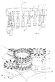
- Fig. 6 shows a schematic representation of the planetary gear 31.
- This planetary gear 31 has a plurality of devices 1 according to the invention, which are each arranged at the same height, it can be seen, however, that the individual containers 10 are each raised to a maximum position and in this way the Treatment head or the beam finger 5 is immersed in different depths in the containers 10 as a function of the rotational position.
- the devices 1 according to the invention are activated and in this way the inner wall of the containers 10 a is sterilized over the entire height of the containers 10.
- the length of the beam fingers 5 is chosen so that an effective sterilization of the bottoms of the containers 10 is possible.
- Fig. 7 shows a perspective view of an inventive arrangement.
- a further transport carousel 42 is provided, on which the containers are transported.
- the containers are guided past a further sterilization apparatus 1b for containers and sterilized by this further sterilization apparatus 1b on its outer wall. Subsequently, as described above, the interior of the containers 10 is sterilized.
- the reference numeral 44 refers to turning means such as turntables, by means of which the containers 10 are rotated about their longitudinal direction (or longitudinal axis). By this rotation, a larger area of the outer periphery of the containers 10 can be sterilized. It would also be possible, in the transport direction of the containers 10, to provide a plurality of sterilization devices 1b in succession.
- the container 10 preforms and for the sterilization of already shaped containers 10.
- a sealing device (not shown) may be arranged, which is movable on the one hand relative to the treatment head 5 in the longitudinal direction and on the other hand at an occurrence of Treatment head 5 in the container 10, the space between the treatment head 5 and the mouth 10b of the container 10 seals.
- an opening could be arranged, via which air can be sucked out of the container 10 in order to produce a (partial) vacuum in the interior of the container 10.
- the entire device or a plurality of such devices could be arranged in a space or a housing, which is subjected to a (partial) vacuum.
- the above-mentioned cooling of the treatment head 5 by means of air can be carried out both during the actual emission of electrons and in those periods in which no irradiation is carried out.
Landscapes
- Health & Medical Sciences (AREA)
- General Health & Medical Sciences (AREA)
- Epidemiology (AREA)
- Life Sciences & Earth Sciences (AREA)
- Animal Behavior & Ethology (AREA)
- Public Health (AREA)
- Veterinary Medicine (AREA)
- Toxicology (AREA)
- Engineering & Computer Science (AREA)
- Mechanical Engineering (AREA)
- Apparatus For Disinfection Or Sterilisation (AREA)
Priority Applications (1)
| Application Number | Priority Date | Filing Date | Title |
|---|---|---|---|
| EP12169537.3A EP2492202B1 (fr) | 2008-08-30 | 2009-08-18 | Stérilisation par rayonnement d'électrons pour récipients |
Applications Claiming Priority (1)
| Application Number | Priority Date | Filing Date | Title |
|---|---|---|---|
| DE102008045187A DE102008045187A1 (de) | 2008-08-30 | 2008-08-30 | Elektronenstrahlsterilisation für Behältnisse |
Related Child Applications (2)
| Application Number | Title | Priority Date | Filing Date |
|---|---|---|---|
| EP12169537.3A Division EP2492202B1 (fr) | 2008-08-30 | 2009-08-18 | Stérilisation par rayonnement d'électrons pour récipients |
| EP12169537.3 Division-Into | 2012-05-25 |
Publications (2)
| Publication Number | Publication Date |
|---|---|
| EP2161202A1 true EP2161202A1 (fr) | 2010-03-10 |
| EP2161202B1 EP2161202B1 (fr) | 2012-10-31 |
Family
ID=41361219
Family Applications (2)
| Application Number | Title | Priority Date | Filing Date |
|---|---|---|---|
| EP12169537.3A Active EP2492202B1 (fr) | 2008-08-30 | 2009-08-18 | Stérilisation par rayonnement d'électrons pour récipients |
| EP09168082A Active EP2161202B1 (fr) | 2008-08-30 | 2009-08-18 | Stérilisation par rayonnement d'électrons pour récipients |
Family Applications Before (1)
| Application Number | Title | Priority Date | Filing Date |
|---|---|---|---|
| EP12169537.3A Active EP2492202B1 (fr) | 2008-08-30 | 2009-08-18 | Stérilisation par rayonnement d'électrons pour récipients |
Country Status (5)
| Country | Link |
|---|---|
| US (1) | US8821788B2 (fr) |
| EP (2) | EP2492202B1 (fr) |
| JP (1) | JP5554524B2 (fr) |
| CN (2) | CN101658683B (fr) |
| DE (1) | DE102008045187A1 (fr) |
Cited By (20)
| Publication number | Priority date | Publication date | Assignee | Title |
|---|---|---|---|---|
| WO2011011079A1 (fr) * | 2009-07-22 | 2011-01-27 | Advanced Electron Beams | Appareil amélioré de stérilisation par faisceau délectrons |
| FR2953414A1 (fr) * | 2009-12-03 | 2011-06-10 | Hema | Dispositif de traitement pour la sterilisation de recipients et le remplissage desdits recipients |
| EP2371397A1 (fr) * | 2010-03-23 | 2011-10-05 | Krones AG | Dispositif de stérilisation de récipients |
| ITPR20100054A1 (it) * | 2010-06-11 | 2011-12-12 | Gea Procomac Spa | Dispositivo di formatura di un recipiente ottenuto da una preforma in materiale plastico, metodo di formatura e macchina di formatura |
| ITPR20100062A1 (it) * | 2010-07-15 | 2012-01-16 | Gea Procomac Spa | Metodo ed apparato di formatura in asettico di contenitori in materiale plastico |
| EP2491955A1 (fr) * | 2011-02-24 | 2012-08-29 | Krones AG | Procédé et dispositif destinés à la stérilisation de récipients |
| US8293173B2 (en) | 2009-04-30 | 2012-10-23 | Hitachi Zosen Corporation | Electron beam sterilization apparatus |
| EP2559444A1 (fr) * | 2011-08-19 | 2013-02-20 | Krones AG | Dispositif de stérilisation de récipients en plastique avec dispositif de protection |
| DE102011054097A1 (de) * | 2011-09-30 | 2013-04-04 | Krones Aktiengesellschaft | Vorrichtung und Verfahren zum Sterilisieren von Behältnissen mit in die Behältnisse eingeführter Ladungsträgerquelle |
| DE102011055005A1 (de) * | 2011-11-02 | 2013-05-02 | Krones Ag | Vorrichtung zum Sterilisieren von Kunststoffbehältnissen mittels mediengesteuerter Elektronenstrahlen |
| DE102011055550A1 (de) * | 2011-11-21 | 2013-05-23 | Krones Ag | Vorrichtung und Verfahren zum Sterilisieren von Kunststoffbehältnissen mit Elektronenstrahlung |
| EP2601975A1 (fr) * | 2011-12-08 | 2013-06-12 | Krones AG | Dispositif et procédé de stérilisation de parois intérieures de récipients à l'aide d'un dispositif réflecteur pour radiation électronique |
| EP2687236A1 (fr) * | 2012-07-19 | 2014-01-22 | Krones AG | Procédé et dispositif de stérilisation de récipients avec prélèvement d'air de refroidissement hors de la chambre stérile |
| EP2719399A1 (fr) * | 2012-10-09 | 2014-04-16 | Krones AG | Stérilisation de récipients au moyen de faisceaux d'électrons avec protection contre le rayonnement pour les doigts de faisceaux |
| DE102012112368A1 (de) * | 2012-12-17 | 2014-06-18 | Krones Ag | Vorrichtung und Verfahren zum Rinsen |
| DE102013101642A1 (de) | 2013-02-19 | 2014-08-21 | Khs Gmbh | Verfahren und Vorrichtung zum Herstellen und Füllen von Behältern |
| EP2842579A1 (fr) * | 2013-09-03 | 2015-03-04 | Krones AG | Procédé et dispositif de stabilisation de récipients doté d'un dispositif de nettoyage d'une fenêtre de faisceau |
| WO2015144379A1 (fr) * | 2014-03-28 | 2015-10-01 | Krones Ag | Procédé et système de contrôle de récipients remplis |
| EP3733217A1 (fr) * | 2019-04-02 | 2020-11-04 | Krones AG | Dispositif et procédé de stérilisation de fermetures de récipient |
| EP4342500A3 (fr) * | 2022-09-05 | 2024-05-29 | Krones Ag | Dispositif et procédé de désinfection de récipients |
Families Citing this family (39)
| Publication number | Priority date | Publication date | Assignee | Title |
|---|---|---|---|---|
| DE102009018210C5 (de) | 2009-04-21 | 2022-08-18 | Khs Gmbh | Verfahren und Vorrichtung zur Überwachung der Intensität eines Elektronenstrahles |
| DE102009061727B4 (de) * | 2009-12-07 | 2017-09-14 | Crosslinking AB | Elektronenstrahleinheit mit Strahlfeldbegrenzung und Verfahren dazu |
| ES2610626T3 (es) * | 2010-02-08 | 2017-04-28 | Tetra Laval Holdings & Finance S.A. | Conjunto y método para reducir las arrugas de las láminas en una disposición circular |
| US8981316B2 (en) * | 2010-04-02 | 2015-03-17 | Abbott Cardiovascular Systems Inc. | Radiation sterilization of implantable medical devices |
| JP5737885B2 (ja) * | 2010-08-30 | 2015-06-17 | 三菱重工業株式会社 | 電子線殺菌装置 |
| DE102010044244A1 (de) * | 2010-09-02 | 2012-03-08 | Khs Gmbh | Verfahren sowie Vorrichtung zum Behandeln von Behältern |
| JP5645562B2 (ja) * | 2010-09-10 | 2014-12-24 | 三菱重工業株式会社 | 電子線殺菌装置 |
| JP5621567B2 (ja) * | 2010-12-10 | 2014-11-12 | 澁谷工業株式会社 | 電子線殺菌装置 |
| DE102011107772A1 (de) * | 2011-07-15 | 2013-01-17 | Krones Aktiengesellschaft | Verfahren und Vorrichtung zum Herstellen von mit Flüssigkeiten gefüllten Getränkebehältnissen |
| DE102011055555A1 (de) * | 2011-11-21 | 2013-05-23 | Krones Ag | Vorrichtung zum Sterilisieren eines Behältnisses, Getränkeabfüllanlage und/oder Getränkebehälterherstellanlage sowie Verfahren zum Sterilisieren eines ein von einer Innenwandung umgrenzten Volumen aufweisenden Behältnisses |
| DE102011056628A1 (de) * | 2011-12-19 | 2013-06-20 | Krones Aktiengesellschaft | Vorrichtung und Verfahren zum Sterilisieren von Behältnissen mit Funktionsüberwachung |
| DE102012110108A1 (de) * | 2012-10-23 | 2014-04-24 | Krones Ag | Vorrichtung zur Außensterilisation von Kunststoffvorformlingen |
| DE102012112158A1 (de) * | 2012-12-12 | 2014-06-12 | Krones Ag | Vorrichtung zum Sterilisieren von Kunststoffvorformlingen |
| WO2014095839A1 (fr) * | 2012-12-20 | 2014-06-26 | Tetra Laval Holdings & Finance S.A. | Dispositif et procédé pour irradier des conteneurs d'emballage par faisceau d'électrons |
| DE102013101407A1 (de) * | 2013-02-13 | 2014-08-14 | Khs Gmbh | Verfahren zum Verpacken von flüssigen Produkten unter Druck in Flaschen aus Kunststoff oder dgl. Behälter |
| WO2014206861A1 (fr) * | 2013-06-25 | 2014-12-31 | Tetra Laval Holdings & Finance S.A. | Procédé et dispositif pour stériliser un matériau d'emballage |
| DE102013013589A1 (de) * | 2013-08-19 | 2015-02-19 | Khs Corpoplast Gmbh | Vorrichtung und Verfahren zur Herstellung steriler Behälter |
| JP6076238B2 (ja) * | 2013-11-28 | 2017-02-08 | 日立造船株式会社 | 電子線滅菌装置 |
| FR3014352B1 (fr) | 2013-12-09 | 2016-01-22 | Sidel Participations | Dispositif de traitement en serie de corps creux comportant une tige de traitement commandee en coulissement par un actionneur electrique et procede de traitement |
| US9850014B2 (en) | 2014-01-31 | 2017-12-26 | Tetra Laval Holdings & Finance S.A. | Device and method for sterilizing a packaging container |
| DE102014105974A1 (de) | 2014-04-29 | 2015-10-29 | Khs Gmbh | Behälterbehandlungsmaschine sowie Verfahren zum Behandeln von Behältern |
| JP6433256B2 (ja) * | 2014-11-18 | 2018-12-05 | 日立造船株式会社 | 電子線滅菌装置 |
| JP6080918B2 (ja) * | 2015-07-30 | 2017-02-15 | 日立造船株式会社 | 電子線殺菌設備及び電子線殺菌方法 |
| DE102016006880B3 (de) * | 2016-06-06 | 2017-08-17 | Crosslinking AB | Verfahren zum Bestrahlen eines Behältnisses sowie Elektronenbestrahlungseinheit dazu |
| DE102017101745A1 (de) | 2017-01-30 | 2018-08-02 | Krones Ag | Vorrichtung und Verfahren zum Sterilisieren von Kunststoffvorformlingen mit vorangegangener Prüfung der Kunststoffvorformlinge |
| US11241513B1 (en) * | 2017-09-20 | 2022-02-08 | Jonathan J. Ricciardi | Methods and apparatuses for applying agents to objects and packaging objects |
| JP6920268B2 (ja) * | 2018-11-01 | 2021-08-18 | 日立造船株式会社 | 電子線滅菌設備のバリデーション方法 |
| CN112969480B (zh) * | 2018-11-09 | 2023-04-18 | 西得乐集团 | 热塑性材料容器的辐照灭菌方法和装置 |
| WO2020114824A1 (fr) | 2018-12-04 | 2020-06-11 | Tetra Laval Holdings & Finance S.A. | Procédé, dispositif et système de stérilisation de matériau d'emballage d'emballages |
| IT201900009591A1 (it) * | 2019-06-20 | 2020-12-20 | Smi Spa | Sistema per la disinfezione interna di contenitori |
| CN110921599B (zh) * | 2019-12-13 | 2021-05-25 | 嵊州市雾非雾机械设备商行 | 一种液体分装设备 |
| DE102020103592A1 (de) | 2020-02-12 | 2021-08-12 | Krones Aktiengesellschaft | Testbehältnis zur Messung einer Bestrahlungsleistung in Sterilisationsanlagen und Dosimetrieverfahren für Bestrahlungsleistung |
| CN111747366A (zh) * | 2020-07-03 | 2020-10-09 | 杨文玮 | 一种灌装食品带二次灭菌的灌装装置 |
| FR3115995B1 (fr) * | 2020-11-09 | 2022-10-28 | Capsum | Appareil de décontamination d’un objet creux définissant une cavité interne, machine de distribution et procédé associés |
| CN114832124A (zh) * | 2021-02-02 | 2022-08-02 | 湖州超群电子科技有限公司 | 一种开口容器用电子辐照杀菌消毒系统及其使用方法 |
| CN113101399B (zh) * | 2021-04-19 | 2022-04-19 | 虞连奎 | 一种医疗骨科器械的自动消毒与烘干设备 |
| DE102021110223A1 (de) | 2021-04-22 | 2021-06-02 | Krones Aktiengesellschaft | Vorrichtung und Verfahren zum Behandeln der Innenwandungen von Behältnissen |
| DE102021134504A1 (de) * | 2021-12-23 | 2023-06-29 | Krones Aktiengesellschaft | Vorrichtung und Verfahren zum Behandeln und insbesondere Sterilisieren von Behältnissen |
| DE102021134514A1 (de) | 2021-12-23 | 2023-06-29 | Krones Aktiengesellschaft | Vorrichtung und Verfahren zum Behandeln und insbesondere Sterilisieren von Behältnissen |
Citations (7)
| Publication number | Priority date | Publication date | Assignee | Title |
|---|---|---|---|---|
| WO1997007024A1 (fr) * | 1995-08-11 | 1997-02-27 | Tetra Laval Holdings & Finance S.A. | Procede de sterilisation d'emballages pour produits coulants |
| WO1999039751A2 (fr) * | 1998-02-06 | 1999-08-12 | Mediscan Gmbh | Procede de traitement d'un materiau |
| EP1120121A2 (fr) * | 2000-01-26 | 2001-08-01 | Raymond William Sheppard | Système de stérilisation de conteneurs et fermetures par UV |
| US20050173020A1 (en) * | 2002-06-19 | 2005-08-11 | Daniel Py | Sterile filling machine having needle filling station within E-Beam chamber |
| US20060192140A1 (en) * | 2002-08-05 | 2006-08-31 | Nablo Samuel V | Process for electron sterilization of a container |
| US20070283667A1 (en) * | 2006-06-13 | 2007-12-13 | Tetra Laval Holdings & Finance Sa | Method of sterilizing packages |
| EP1944044A1 (fr) * | 2007-01-09 | 2008-07-16 | Becton Dickinson France | Processus et équipement pour décontamination par rayonnement d'un produit |
Family Cites Families (32)
| Publication number | Priority date | Publication date | Assignee | Title |
|---|---|---|---|---|
| US3780308A (en) | 1971-06-07 | 1973-12-18 | Energy Sciences Inc | Process and apparatus for surface sterilization of materials |
| IE38580B1 (en) * | 1972-09-19 | 1978-04-12 | Lilly Co Eli | Method of sterilising containers with a laser beam |
| JPS63281936A (ja) * | 1987-05-14 | 1988-11-18 | Sumitomo Electric Ind Ltd | 容器の殺菌装置 |
| US5378898A (en) * | 1992-09-08 | 1995-01-03 | Zapit Technology, Inc. | Electron beam system |
| JP3104949B2 (ja) | 1994-04-12 | 2000-10-30 | 株式会社栗本鐵工所 | 廃瓶の選別装置 |
| JP3026736B2 (ja) | 1994-09-12 | 2000-03-27 | 住友ゴム工業株式会社 | 空気入りラジアルタイヤ |
| JP3392234B2 (ja) * | 1994-10-12 | 2003-03-31 | 大日本印刷株式会社 | ボトル内面走査方法及び装置 |
| JPH08151021A (ja) * | 1994-11-30 | 1996-06-11 | Iwasaki Electric Co Ltd | 容器の滅菌方法 |
| US6110317A (en) | 1996-09-23 | 2000-08-29 | Sandor; Raymond P. | Decorative design method and products |
| US6221216B1 (en) | 1997-03-26 | 2001-04-24 | Electron Processing Systems, Inc. | Technique for interior electron sterilization of an open mouthed container |
| US6110318A (en) | 1997-11-26 | 2000-08-29 | Science Research Laboratory | System for selective electron beam irradiation |
| JPH11248897A (ja) | 1998-02-27 | 1999-09-17 | Mitsubishi Heavy Ind Ltd | 電子線照射方法及びその装置 |
| JP2000167029A (ja) | 1998-12-01 | 2000-06-20 | Mitsubishi Electric Corp | 放射線照射装置 |
| DE60045551D1 (de) | 1999-07-09 | 2011-03-03 | Advanced Electron Beams Inc A Delaware Corp | Elektronenstrahlbeschleuniger |
| JP2001174559A (ja) * | 1999-12-20 | 2001-06-29 | Nissin High Voltage Co Ltd | 特定箇所の線量測定方法 |
| US6617596B1 (en) | 2000-11-17 | 2003-09-09 | Steris Inc. | On-line measurement of absorbed electron beam dosage in irradiated product |
| JP2003156600A (ja) | 2001-11-20 | 2003-05-30 | Mitsubishi Heavy Ind Ltd | 電子線均一照射方法及び装置 |
| JP4148391B2 (ja) * | 2002-02-06 | 2008-09-10 | 三菱重工食品包装機械株式会社 | 殺菌装置及び殺菌方法 |
| DE60308341T2 (de) * | 2002-03-28 | 2007-05-03 | Apit Corp. Sa | Verfahren zur oberflächenbehandlung durch atmosphärisches plasma und vorrichtung zu seiner herstellung |
| US7641851B2 (en) * | 2003-12-23 | 2010-01-05 | Baxter International Inc. | Method and apparatus for validation of sterilization process |
| DE102004032861A1 (de) | 2004-07-07 | 2006-02-02 | Khs Maschinen- Und Anlagenbau Ag | Verfahren sowie Vorrichtung zum Sterilisieren von Behältern mit UV-Strahlung |
| ES2594360T3 (es) | 2005-02-10 | 2016-12-19 | Nestec S.A. | Aparato y método para irradiar productos alimenticios fluidos |
| US8232728B2 (en) * | 2005-09-09 | 2012-07-31 | Inp Institut Fuer Niedertemperatur-Plasmaphysik E.V. | Method and device for igniting and generating an expanding diffuse microwave plasma and method and device for plasma treating surfaces and substances by using this plasma |
| DE102005043278B4 (de) * | 2005-09-09 | 2011-02-03 | Leibniz-Institut für Plasmaforschung und Technologie e.V. | Verfahren und Vorrichtung zum Erzeugen eines sich ausdehnenden, diffusen Mikrowellenplasmas |
| JP4848173B2 (ja) * | 2005-11-02 | 2011-12-28 | 三菱重工業株式会社 | 食品容器の電子線殺菌検査システム及び食品容器の電子線殺菌検査方法 |
| WO2007095205A2 (fr) | 2006-02-14 | 2007-08-23 | Advanced Electron Beams, Inc. | Emetteur de faisceau electronique |
| DE102006025736A1 (de) | 2006-05-31 | 2007-12-06 | RUHR-UNIVERSITäT BOCHUM | Sterilisationsverfahren |
| WO2007145561A1 (fr) | 2006-06-13 | 2007-12-21 | Tetra Laval Holdings & Finance S.A. | Procédé de stérilisation d'emballages |
| CN101108254B (zh) * | 2006-07-17 | 2010-08-25 | 清华大学 | 移动式电子束辐照灭菌设备 |
| SE530589C2 (sv) | 2006-12-11 | 2008-07-15 | Tetra Laval Holdings & Finance | Metod att bestråla föremål |
| DE102007017938C5 (de) * | 2007-04-13 | 2017-09-21 | Khs Gmbh | Behälterherstellungsvorrichtung und Herstellverfahren für Formkörper |
| EP1982920A1 (fr) | 2007-04-19 | 2008-10-22 | Krones AG | Dispositif de stérilisation de récipients |
-
2008
- 2008-08-30 DE DE102008045187A patent/DE102008045187A1/de active Pending
-
2009
- 2009-08-18 EP EP12169537.3A patent/EP2492202B1/fr active Active
- 2009-08-18 EP EP09168082A patent/EP2161202B1/fr active Active
- 2009-08-21 JP JP2009191606A patent/JP5554524B2/ja active Active
- 2009-08-24 US US12/546,133 patent/US8821788B2/en active Active
- 2009-08-25 CN CN200910171598.XA patent/CN101658683B/zh active Active
- 2009-08-25 CN CN201810819158.XA patent/CN108992679B/zh active Active
Patent Citations (7)
| Publication number | Priority date | Publication date | Assignee | Title |
|---|---|---|---|---|
| WO1997007024A1 (fr) * | 1995-08-11 | 1997-02-27 | Tetra Laval Holdings & Finance S.A. | Procede de sterilisation d'emballages pour produits coulants |
| WO1999039751A2 (fr) * | 1998-02-06 | 1999-08-12 | Mediscan Gmbh | Procede de traitement d'un materiau |
| EP1120121A2 (fr) * | 2000-01-26 | 2001-08-01 | Raymond William Sheppard | Système de stérilisation de conteneurs et fermetures par UV |
| US20050173020A1 (en) * | 2002-06-19 | 2005-08-11 | Daniel Py | Sterile filling machine having needle filling station within E-Beam chamber |
| US20060192140A1 (en) * | 2002-08-05 | 2006-08-31 | Nablo Samuel V | Process for electron sterilization of a container |
| US20070283667A1 (en) * | 2006-06-13 | 2007-12-13 | Tetra Laval Holdings & Finance Sa | Method of sterilizing packages |
| EP1944044A1 (fr) * | 2007-01-09 | 2008-07-16 | Becton Dickinson France | Processus et équipement pour décontamination par rayonnement d'un produit |
Cited By (37)
| Publication number | Priority date | Publication date | Assignee | Title |
|---|---|---|---|---|
| US8293173B2 (en) | 2009-04-30 | 2012-10-23 | Hitachi Zosen Corporation | Electron beam sterilization apparatus |
| WO2011011079A1 (fr) * | 2009-07-22 | 2011-01-27 | Advanced Electron Beams | Appareil amélioré de stérilisation par faisceau délectrons |
| FR2953414A1 (fr) * | 2009-12-03 | 2011-06-10 | Hema | Dispositif de traitement pour la sterilisation de recipients et le remplissage desdits recipients |
| EP2371397A1 (fr) * | 2010-03-23 | 2011-10-05 | Krones AG | Dispositif de stérilisation de récipients |
| ITPR20100054A1 (it) * | 2010-06-11 | 2011-12-12 | Gea Procomac Spa | Dispositivo di formatura di un recipiente ottenuto da una preforma in materiale plastico, metodo di formatura e macchina di formatura |
| WO2011154868A3 (fr) * | 2010-06-11 | 2012-03-29 | Gea Procomac S.P.A. | Dispositif pour mouler un récipient obtenu à partir d'une paraison de matière plastique, procédé de moulage et machine de moulage |
| US9144932B2 (en) | 2010-06-11 | 2015-09-29 | Gea Procomac S.P.A. | Device for moulding a receptacle obtained from a parison of plastic material, a moulding method and a moulding machine |
| US8980157B2 (en) | 2010-07-15 | 2015-03-17 | GEA Procomac S.p.A | Method and apparatus for aseptic moulding of containers of plastic material |
| ITPR20100062A1 (it) * | 2010-07-15 | 2012-01-16 | Gea Procomac Spa | Metodo ed apparato di formatura in asettico di contenitori in materiale plastico |
| WO2012007862A3 (fr) * | 2010-07-15 | 2012-06-07 | Gea Procomac S.P.A. | Procédé et appareil destinés au moulage aseptique de récipients constitués de plastique |
| EP2491955A1 (fr) * | 2011-02-24 | 2012-08-29 | Krones AG | Procédé et dispositif destinés à la stérilisation de récipients |
| US9155807B2 (en) | 2011-02-24 | 2015-10-13 | Krones Ag | Method and apparatus for the sterilization of containers |
| EP2559444A1 (fr) * | 2011-08-19 | 2013-02-20 | Krones AG | Dispositif de stérilisation de récipients en plastique avec dispositif de protection |
| US9078935B2 (en) | 2011-09-30 | 2015-07-14 | Krones Ag | Apparatus and method of sterilizing containers with a charge carrier source introduced into the containers |
| DE102011054097A1 (de) * | 2011-09-30 | 2013-04-04 | Krones Aktiengesellschaft | Vorrichtung und Verfahren zum Sterilisieren von Behältnissen mit in die Behältnisse eingeführter Ladungsträgerquelle |
| EP2581096A1 (fr) * | 2011-09-30 | 2013-04-17 | Krones AG | Dispositif et procédé de stérilisation de récipients avec source de support de charge introduite dans les récipients |
| US8961871B2 (en) | 2011-11-02 | 2015-02-24 | Krones Ag | Apparatus for the sterilization of plastics material containers by means of medium-controlled electron beams |
| DE102011055005A1 (de) * | 2011-11-02 | 2013-05-02 | Krones Ag | Vorrichtung zum Sterilisieren von Kunststoffbehältnissen mittels mediengesteuerter Elektronenstrahlen |
| DE102011055550A1 (de) * | 2011-11-21 | 2013-05-23 | Krones Ag | Vorrichtung und Verfahren zum Sterilisieren von Kunststoffbehältnissen mit Elektronenstrahlung |
| EP2601975A1 (fr) * | 2011-12-08 | 2013-06-12 | Krones AG | Dispositif et procédé de stérilisation de parois intérieures de récipients à l'aide d'un dispositif réflecteur pour radiation électronique |
| CN103157120A (zh) * | 2011-12-08 | 2013-06-19 | 克朗斯股份公司 | 使用反射器设备对容器的内壁进行杀菌的设备和方法 |
| US8728393B2 (en) | 2011-12-08 | 2014-05-20 | Krones Ag | Apparatus and method of sterilizing inner walls of containers with a reflector apparatus |
| CN103157120B (zh) * | 2011-12-08 | 2015-07-29 | 克朗斯股份公司 | 使用反射器设备对容器的内壁进行杀菌的设备和方法 |
| EP2687236A1 (fr) * | 2012-07-19 | 2014-01-22 | Krones AG | Procédé et dispositif de stérilisation de récipients avec prélèvement d'air de refroidissement hors de la chambre stérile |
| EP2719399A1 (fr) * | 2012-10-09 | 2014-04-16 | Krones AG | Stérilisation de récipients au moyen de faisceaux d'électrons avec protection contre le rayonnement pour les doigts de faisceaux |
| DE102012112368A1 (de) * | 2012-12-17 | 2014-06-18 | Krones Ag | Vorrichtung und Verfahren zum Rinsen |
| WO2014095937A1 (fr) * | 2012-12-17 | 2014-06-26 | Krones Ag | Dispositif et procédé pour stériliser et rincer des récipients |
| DE102013101642A1 (de) | 2013-02-19 | 2014-08-21 | Khs Gmbh | Verfahren und Vorrichtung zum Herstellen und Füllen von Behältern |
| US11345073B2 (en) | 2013-02-19 | 2022-05-31 | Khs Gmbh | Method and device for producing and filling containers |
| EP2842579A1 (fr) * | 2013-09-03 | 2015-03-04 | Krones AG | Procédé et dispositif de stabilisation de récipients doté d'un dispositif de nettoyage d'une fenêtre de faisceau |
| US9358312B2 (en) | 2013-09-03 | 2016-06-07 | Krones Ag | Method and apparatus for the sterilization of containers with cleaning of a radiation outlet window |
| WO2015144379A1 (fr) * | 2014-03-28 | 2015-10-01 | Krones Ag | Procédé et système de contrôle de récipients remplis |
| US20170081052A1 (en) * | 2014-03-28 | 2017-03-23 | Krones Ag | Method for monitoring a filled container and monitoring system for filled containers |
| US10336476B2 (en) | 2014-03-28 | 2019-07-02 | Krones Ag | Method for monitoring a filled container and monitoring system for filled containers |
| EP3733217A1 (fr) * | 2019-04-02 | 2020-11-04 | Krones AG | Dispositif et procédé de stérilisation de fermetures de récipient |
| EP3925628A1 (fr) * | 2019-04-02 | 2021-12-22 | Krones Ag | Dispositif et procédé de stérilisation des fermetures de récipients |
| EP4342500A3 (fr) * | 2022-09-05 | 2024-05-29 | Krones Ag | Dispositif et procédé de désinfection de récipients |
Also Published As
| Publication number | Publication date |
|---|---|
| US8821788B2 (en) | 2014-09-02 |
| JP5554524B2 (ja) | 2014-07-23 |
| EP2492202B1 (fr) | 2014-12-17 |
| US20100054987A1 (en) | 2010-03-04 |
| DE102008045187A1 (de) | 2010-03-04 |
| CN101658683A (zh) | 2010-03-03 |
| CN101658683B (zh) | 2018-08-28 |
| EP2492202A1 (fr) | 2012-08-29 |
| CN108992679A (zh) | 2018-12-14 |
| CN108992679B (zh) | 2021-08-20 |
| JP2010058843A (ja) | 2010-03-18 |
| EP2161202B1 (fr) | 2012-10-31 |
Similar Documents
| Publication | Publication Date | Title |
|---|---|---|
| EP2161202B1 (fr) | Stérilisation par rayonnement d'électrons pour récipients | |
| EP2371397B1 (fr) | Dispositif de stérilisation de récipients | |
| EP2491955B1 (fr) | Procédé et dispositif destinés à la stérilisation de récipients | |
| EP2431058B1 (fr) | Unité de stérilisation aseptisée pour une salle blanche | |
| EP2796269B1 (fr) | Dispositif et procédé de stérilisation extérieure de préformes en matière plastique | |
| DE102008007428B4 (de) | Verfahren sowie Vorrichtung zum Sterilisieren von Packmitteln | |
| EP2650022B1 (fr) | Dispositif et procédé destinés à la stérilisation à base de rayonnement de fermetures de récipients | |
| EP2746029B1 (fr) | Dispositif et procédé destinés à la stérilisation de récipients | |
| EP2724731A1 (fr) | Dispositif de stérilisation extérieure d'ébauches en plastique | |
| EP2594493A2 (fr) | Dispositif de stérilisation intérieure et extérieure de récipients en plastique au moyen du rayonnement d'un support de chargement et méthod et ligne de traitement correspondant | |
| EP2687478A1 (fr) | Dispositif et procédé destinés au traitement de bouchons pour récipients | |
| EP4227232A2 (fr) | Dispositif et procédé de traitement et notamment de stérilisation de récipients | |
| EP4272767A1 (fr) | Dispositif et procédé de stérilisation de récipients | |
| EP3699100A1 (fr) | Dispositif et procédé de fabrication de récipients remplis | |
| EP3699102A1 (fr) | Dispositif et procédé de fabrication de récipients remplis | |
| EP2594492B1 (fr) | Dispositif de stérilisation d'un récipient, installation de remplissage de boissons et/ou installation de fabrication de récipients de boissons ainsi que le procédé de stérilisation d'un récipient contenant des volumes limités par une paroi intérieure | |
| EP2842579B1 (fr) | Procédé et dispositif de stérilisation de récipients avec un dispositif de nettoyage d'une fenêtre de rayon | |
| DE102021134504A1 (de) | Vorrichtung und Verfahren zum Behandeln und insbesondere Sterilisieren von Behältnissen | |
| DE102021134541A1 (de) | Vorrichtung und Verfahren zum Behandeln und insbesondere Sterilisieren von Behältnissen | |
| DE102016125721A1 (de) | Verfahren und Vorrichtung zum Sterilisieren von Behältnissen | |
| EP4209231A1 (fr) | Dispositif et procédé de traitement et notamment de stérilisation de récipients | |
| EP4201433A1 (fr) | Dispositif et procédé de traitement et notamment de stérilisation de récipients | |
| DE102021134518A1 (de) | Vorrichtung und Verfahren zum Behandeln und insbesondere Sterilisieren von Behältnissen | |
| DE102021134523A1 (de) | Vorrichtung und Verfahren zum Behandeln und insbesondere Sterilisieren von Behältnissen | |
| DE10340916A1 (de) | Verfahren und Vorrichtung zur Handhabung von Werkstücken |
Legal Events
| Date | Code | Title | Description |
|---|---|---|---|
| PUAI | Public reference made under article 153(3) epc to a published international application that has entered the european phase |
Free format text: ORIGINAL CODE: 0009012 |
|
| AK | Designated contracting states |
Kind code of ref document: A1 Designated state(s): AT BE BG CH CY CZ DE DK EE ES FI FR GB GR HR HU IE IS IT LI LT LU LV MC MK MT NL NO PL PT RO SE SI SK SM TR |
|
| 17P | Request for examination filed |
Effective date: 20100408 |
|
| 17Q | First examination report despatched |
Effective date: 20100525 |
|
| GRAP | Despatch of communication of intention to grant a patent |
Free format text: ORIGINAL CODE: EPIDOSNIGR1 |
|
| RIC1 | Information provided on ipc code assigned before grant |
Ipc: A61L 2/24 20060101ALI20120229BHEP Ipc: A61L 2/08 20060101ALI20120229BHEP Ipc: B65B 55/08 20060101AFI20120229BHEP Ipc: B67C 7/00 20060101ALI20120229BHEP |
|
| RIN1 | Information on inventor provided before grant (corrected) |
Inventor name: KRUEGER, JOCHEN Inventor name: HUMELE, HEINZ |
|
| RIN1 | Information on inventor provided before grant (corrected) |
Inventor name: KRUEGER, JOCHEN Inventor name: HUMELE, HEINZ |
|
| GRAS | Grant fee paid |
Free format text: ORIGINAL CODE: EPIDOSNIGR3 |
|
| GRAA | (expected) grant |
Free format text: ORIGINAL CODE: 0009210 |
|
| AK | Designated contracting states |
Kind code of ref document: B1 Designated state(s): AT BE BG CH CY CZ DE DK EE ES FI FR GB GR HR HU IE IS IT LI LT LU LV MC MK MT NL NO PL PT RO SE SI SK SM TR |
|
| REG | Reference to a national code |
Ref country code: GB Ref legal event code: FG4D Free format text: NOT ENGLISH Ref country code: CH Ref legal event code: EP |
|
| REG | Reference to a national code |
Ref country code: AT Ref legal event code: REF Ref document number: 581861 Country of ref document: AT Kind code of ref document: T Effective date: 20121115 |
|
| REG | Reference to a national code |
Ref country code: IE Ref legal event code: FG4D Free format text: LANGUAGE OF EP DOCUMENT: GERMAN |
|
| REG | Reference to a national code |
Ref country code: DE Ref legal event code: R096 Ref document number: 502009005238 Country of ref document: DE Effective date: 20121227 |
|
| REG | Reference to a national code |
Ref country code: CH Ref legal event code: NV Representative=s name: ROTTMANN, ZIMMERMANN + PARTNER AG, CH |
|
| REG | Reference to a national code |
Ref country code: CH Ref legal event code: NV Representative=s name: ROTTMANN, ZIMMERMANN + PARTNER AG, CH |
|
| REG | Reference to a national code |
Ref country code: SE Ref legal event code: TRGR |
|
| REG | Reference to a national code |
Ref country code: LT Ref legal event code: MG4D |
|
| REG | Reference to a national code |
Ref country code: NL Ref legal event code: VDEP Effective date: 20121031 |
|
| PG25 | Lapsed in a contracting state [announced via postgrant information from national office to epo] |
Ref country code: LT Free format text: LAPSE BECAUSE OF FAILURE TO SUBMIT A TRANSLATION OF THE DESCRIPTION OR TO PAY THE FEE WITHIN THE PRESCRIBED TIME-LIMIT Effective date: 20121031 Ref country code: IS Free format text: LAPSE BECAUSE OF FAILURE TO SUBMIT A TRANSLATION OF THE DESCRIPTION OR TO PAY THE FEE WITHIN THE PRESCRIBED TIME-LIMIT Effective date: 20130228 Ref country code: ES Free format text: LAPSE BECAUSE OF FAILURE TO SUBMIT A TRANSLATION OF THE DESCRIPTION OR TO PAY THE FEE WITHIN THE PRESCRIBED TIME-LIMIT Effective date: 20130211 Ref country code: NO Free format text: LAPSE BECAUSE OF FAILURE TO SUBMIT A TRANSLATION OF THE DESCRIPTION OR TO PAY THE FEE WITHIN THE PRESCRIBED TIME-LIMIT Effective date: 20130131 Ref country code: HR Free format text: LAPSE BECAUSE OF FAILURE TO SUBMIT A TRANSLATION OF THE DESCRIPTION OR TO PAY THE FEE WITHIN THE PRESCRIBED TIME-LIMIT Effective date: 20121031 Ref country code: FI Free format text: LAPSE BECAUSE OF FAILURE TO SUBMIT A TRANSLATION OF THE DESCRIPTION OR TO PAY THE FEE WITHIN THE PRESCRIBED TIME-LIMIT Effective date: 20121031 Ref country code: NL Free format text: LAPSE BECAUSE OF FAILURE TO SUBMIT A TRANSLATION OF THE DESCRIPTION OR TO PAY THE FEE WITHIN THE PRESCRIBED TIME-LIMIT Effective date: 20121031 |
|
| PG25 | Lapsed in a contracting state [announced via postgrant information from national office to epo] |
Ref country code: PL Free format text: LAPSE BECAUSE OF FAILURE TO SUBMIT A TRANSLATION OF THE DESCRIPTION OR TO PAY THE FEE WITHIN THE PRESCRIBED TIME-LIMIT Effective date: 20121031 Ref country code: GR Free format text: LAPSE BECAUSE OF FAILURE TO SUBMIT A TRANSLATION OF THE DESCRIPTION OR TO PAY THE FEE WITHIN THE PRESCRIBED TIME-LIMIT Effective date: 20130201 Ref country code: LV Free format text: LAPSE BECAUSE OF FAILURE TO SUBMIT A TRANSLATION OF THE DESCRIPTION OR TO PAY THE FEE WITHIN THE PRESCRIBED TIME-LIMIT Effective date: 20121031 Ref country code: PT Free format text: LAPSE BECAUSE OF FAILURE TO SUBMIT A TRANSLATION OF THE DESCRIPTION OR TO PAY THE FEE WITHIN THE PRESCRIBED TIME-LIMIT Effective date: 20130228 Ref country code: SI Free format text: LAPSE BECAUSE OF FAILURE TO SUBMIT A TRANSLATION OF THE DESCRIPTION OR TO PAY THE FEE WITHIN THE PRESCRIBED TIME-LIMIT Effective date: 20121031 |
|
| PG25 | Lapsed in a contracting state [announced via postgrant information from national office to epo] |
Ref country code: CZ Free format text: LAPSE BECAUSE OF FAILURE TO SUBMIT A TRANSLATION OF THE DESCRIPTION OR TO PAY THE FEE WITHIN THE PRESCRIBED TIME-LIMIT Effective date: 20121031 Ref country code: EE Free format text: LAPSE BECAUSE OF FAILURE TO SUBMIT A TRANSLATION OF THE DESCRIPTION OR TO PAY THE FEE WITHIN THE PRESCRIBED TIME-LIMIT Effective date: 20121031 Ref country code: SK Free format text: LAPSE BECAUSE OF FAILURE TO SUBMIT A TRANSLATION OF THE DESCRIPTION OR TO PAY THE FEE WITHIN THE PRESCRIBED TIME-LIMIT Effective date: 20121031 Ref country code: BG Free format text: LAPSE BECAUSE OF FAILURE TO SUBMIT A TRANSLATION OF THE DESCRIPTION OR TO PAY THE FEE WITHIN THE PRESCRIBED TIME-LIMIT Effective date: 20130131 Ref country code: DK Free format text: LAPSE BECAUSE OF FAILURE TO SUBMIT A TRANSLATION OF THE DESCRIPTION OR TO PAY THE FEE WITHIN THE PRESCRIBED TIME-LIMIT Effective date: 20121031 |
|
| PLBI | Opposition filed |
Free format text: ORIGINAL CODE: 0009260 |
|
| PG25 | Lapsed in a contracting state [announced via postgrant information from national office to epo] |
Ref country code: RO Free format text: LAPSE BECAUSE OF FAILURE TO SUBMIT A TRANSLATION OF THE DESCRIPTION OR TO PAY THE FEE WITHIN THE PRESCRIBED TIME-LIMIT Effective date: 20121031 |
|
| PLAX | Notice of opposition and request to file observation + time limit sent |
Free format text: ORIGINAL CODE: EPIDOSNOBS2 |
|
| 26 | Opposition filed |
Opponent name: TETRA LAVAL HOLDINGS & FINANCE SA Effective date: 20130730 |
|
| REG | Reference to a national code |
Ref country code: DE Ref legal event code: R026 Ref document number: 502009005238 Country of ref document: DE Effective date: 20130730 |
|
| PG25 | Lapsed in a contracting state [announced via postgrant information from national office to epo] |
Ref country code: CY Free format text: LAPSE BECAUSE OF FAILURE TO SUBMIT A TRANSLATION OF THE DESCRIPTION OR TO PAY THE FEE WITHIN THE PRESCRIBED TIME-LIMIT Effective date: 20121031 |
|
| PLAF | Information modified related to communication of a notice of opposition and request to file observations + time limit |
Free format text: ORIGINAL CODE: EPIDOSCOBS2 |
|
| BERE | Be: lapsed |
Owner name: KRONES A.G. Effective date: 20130831 |
|
| PLBB | Reply of patent proprietor to notice(s) of opposition received |
Free format text: ORIGINAL CODE: EPIDOSNOBS3 |
|
| GBPC | Gb: european patent ceased through non-payment of renewal fee |
Effective date: 20130818 |
|
| PG25 | Lapsed in a contracting state [announced via postgrant information from national office to epo] |
Ref country code: MC Free format text: LAPSE BECAUSE OF FAILURE TO SUBMIT A TRANSLATION OF THE DESCRIPTION OR TO PAY THE FEE WITHIN THE PRESCRIBED TIME-LIMIT Effective date: 20121031 |
|
| REG | Reference to a national code |
Ref country code: IE Ref legal event code: MM4A |
|
| PG25 | Lapsed in a contracting state [announced via postgrant information from national office to epo] |
Ref country code: BE Free format text: LAPSE BECAUSE OF NON-PAYMENT OF DUE FEES Effective date: 20130831 |
|
| PG25 | Lapsed in a contracting state [announced via postgrant information from national office to epo] |
Ref country code: IE Free format text: LAPSE BECAUSE OF NON-PAYMENT OF DUE FEES Effective date: 20130818 Ref country code: GB Free format text: LAPSE BECAUSE OF NON-PAYMENT OF DUE FEES Effective date: 20130818 |
|
| PLAY | Examination report in opposition despatched + time limit |
Free format text: ORIGINAL CODE: EPIDOSNORE2 |
|
| PG25 | Lapsed in a contracting state [announced via postgrant information from national office to epo] |
Ref country code: SM Free format text: LAPSE BECAUSE OF FAILURE TO SUBMIT A TRANSLATION OF THE DESCRIPTION OR TO PAY THE FEE WITHIN THE PRESCRIBED TIME-LIMIT Effective date: 20121031 |
|
| PG25 | Lapsed in a contracting state [announced via postgrant information from national office to epo] |
Ref country code: TR Free format text: LAPSE BECAUSE OF FAILURE TO SUBMIT A TRANSLATION OF THE DESCRIPTION OR TO PAY THE FEE WITHIN THE PRESCRIBED TIME-LIMIT Effective date: 20121031 Ref country code: MT Free format text: LAPSE BECAUSE OF FAILURE TO SUBMIT A TRANSLATION OF THE DESCRIPTION OR TO PAY THE FEE WITHIN THE PRESCRIBED TIME-LIMIT Effective date: 20121031 |
|
| PLAH | Information related to despatch of examination report in opposition + time limit modified |
Free format text: ORIGINAL CODE: EPIDOSCORE2 |
|
| PG25 | Lapsed in a contracting state [announced via postgrant information from national office to epo] |
Ref country code: HU Free format text: LAPSE BECAUSE OF FAILURE TO SUBMIT A TRANSLATION OF THE DESCRIPTION OR TO PAY THE FEE WITHIN THE PRESCRIBED TIME-LIMIT; INVALID AB INITIO Effective date: 20090818 Ref country code: LU Free format text: LAPSE BECAUSE OF NON-PAYMENT OF DUE FEES Effective date: 20130818 Ref country code: MK Free format text: LAPSE BECAUSE OF FAILURE TO SUBMIT A TRANSLATION OF THE DESCRIPTION OR TO PAY THE FEE WITHIN THE PRESCRIBED TIME-LIMIT Effective date: 20121031 |
|
| PLBC | Reply to examination report in opposition received |
Free format text: ORIGINAL CODE: EPIDOSNORE3 |
|
| REG | Reference to a national code |
Ref country code: AT Ref legal event code: MM01 Ref document number: 581861 Country of ref document: AT Kind code of ref document: T Effective date: 20140818 |
|
| PG25 | Lapsed in a contracting state [announced via postgrant information from national office to epo] |
Ref country code: AT Free format text: LAPSE BECAUSE OF NON-PAYMENT OF DUE FEES Effective date: 20140818 |
|
| REG | Reference to a national code |
Ref country code: FR Ref legal event code: PLFP Year of fee payment: 8 |
|
| PLAB | Opposition data, opponent's data or that of the opponent's representative modified |
Free format text: ORIGINAL CODE: 0009299OPPO |
|
| R26 | Opposition filed (corrected) |
Opponent name: TETRA LAVAL HOLDINGS & FINANCE SA Effective date: 20130730 |
|
| REG | Reference to a national code |
Ref country code: CH Ref legal event code: PCAR Free format text: NEW ADDRESS: GARTENSTRASSE 28 A, 5400 BADEN (CH) |
|
| RDAF | Communication despatched that patent is revoked |
Free format text: ORIGINAL CODE: EPIDOSNREV1 |
|
| STAA | Information on the status of an ep patent application or granted ep patent |
Free format text: STATUS: THE PATENT HAS BEEN GRANTED |
|
| APAH | Appeal reference modified |
Free format text: ORIGINAL CODE: EPIDOSCREFNO |
|
| APBM | Appeal reference recorded |
Free format text: ORIGINAL CODE: EPIDOSNREFNO |
|
| APBP | Date of receipt of notice of appeal recorded |
Free format text: ORIGINAL CODE: EPIDOSNNOA2O |
|
| APBQ | Date of receipt of statement of grounds of appeal recorded |
Free format text: ORIGINAL CODE: EPIDOSNNOA3O |
|
| REG | Reference to a national code |
Ref country code: FR Ref legal event code: PLFP Year of fee payment: 9 |
|
| REG | Reference to a national code |
Ref country code: FR Ref legal event code: PLFP Year of fee payment: 10 |
|
| REG | Reference to a national code |
Ref country code: DE Ref legal event code: R100 Ref document number: 502009005238 Country of ref document: DE |
|
| APBU | Appeal procedure closed |
Free format text: ORIGINAL CODE: EPIDOSNNOA9O |
|
| PLAB | Opposition data, opponent's data or that of the opponent's representative modified |
Free format text: ORIGINAL CODE: 0009299OPPO |
|
| PLCK | Communication despatched that opposition was rejected |
Free format text: ORIGINAL CODE: EPIDOSNREJ1 |
|
| RDAE | Information deleted related to despatch of communication that patent is revoked |
Free format text: ORIGINAL CODE: EPIDOSDREV1 |
|
| STAA | Information on the status of an ep patent application or granted ep patent |
Free format text: STATUS: OPPOSITION REJECTED |
|
| PLBN | Opposition rejected |
Free format text: ORIGINAL CODE: 0009273 |
|
| R26 | Opposition filed (corrected) |
Opponent name: TETRA LAVAL HOLDINGS & FINANCE SA Effective date: 20130730 |
|
| 27O | Opposition rejected |
Effective date: 20210115 |
|
| P01 | Opt-out of the competence of the unified patent court (upc) registered |
Effective date: 20230523 |
|
| PGFP | Annual fee paid to national office [announced via postgrant information from national office to epo] |
Ref country code: DE Payment date: 20250702 Year of fee payment: 17 |
|
| PGFP | Annual fee paid to national office [announced via postgrant information from national office to epo] |
Ref country code: IT Payment date: 20250722 Year of fee payment: 17 |
|
| PGFP | Annual fee paid to national office [announced via postgrant information from national office to epo] |
Ref country code: FR Payment date: 20250703 Year of fee payment: 17 |
|
| PGFP | Annual fee paid to national office [announced via postgrant information from national office to epo] |
Ref country code: CH Payment date: 20250901 Year of fee payment: 17 Ref country code: SE Payment date: 20250702 Year of fee payment: 17 |
|
| REG | Reference to a national code |
Ref country code: CH Ref legal event code: R17 Free format text: ST27 STATUS EVENT CODE: U-0-0-R10-R17 (AS PROVIDED BY THE NATIONAL OFFICE) Effective date: 20260410 |