EP2161376A2 - Coupe-joint mobile - Google Patents
Coupe-joint mobile Download PDFInfo
- Publication number
- EP2161376A2 EP2161376A2 EP09164875A EP09164875A EP2161376A2 EP 2161376 A2 EP2161376 A2 EP 2161376A2 EP 09164875 A EP09164875 A EP 09164875A EP 09164875 A EP09164875 A EP 09164875A EP 2161376 A2 EP2161376 A2 EP 2161376A2
- Authority
- EP
- European Patent Office
- Prior art keywords
- saw blade
- chassis frame
- cutter according
- mobile floor
- linear guide
- Prior art date
- Legal status (The legal status is an assumption and is not a legal conclusion. Google has not performed a legal analysis and makes no representation as to the accuracy of the status listed.)
- Granted
Links
Images


Classifications
-
- E—FIXED CONSTRUCTIONS
- E01—CONSTRUCTION OF ROADS, RAILWAYS, OR BRIDGES
- E01C—CONSTRUCTION OF, OR SURFACES FOR, ROADS, SPORTS GROUNDS, OR THE LIKE; MACHINES OR AUXILIARY TOOLS FOR CONSTRUCTION OR REPAIR
- E01C23/00—Auxiliary devices or arrangements for constructing, repairing, reconditioning, or taking-up road or like surfaces
- E01C23/06—Devices or arrangements for working the finished surface; Devices for repairing or reconditioning the surface of damaged paving; Recycling in place or on the road
- E01C23/09—Devices or arrangements for working the finished surface; Devices for repairing or reconditioning the surface of damaged paving; Recycling in place or on the road for forming cuts, grooves, or recesses, e.g. for making joints or channels for markings, for cutting-out sections to be removed; for cleaning, treating, or filling cuts, grooves, recesses, or fissures; for trimming paving edges
- E01C23/0906—Devices or arrangements for working the finished surface; Devices for repairing or reconditioning the surface of damaged paving; Recycling in place or on the road for forming cuts, grooves, or recesses, e.g. for making joints or channels for markings, for cutting-out sections to be removed; for cleaning, treating, or filling cuts, grooves, recesses, or fissures; for trimming paving edges for forming, opening-out, cleaning, drying or heating cuts, grooves, recesses or, excluding forming, cracks, e.g. cleaning by sand-blasting or air-jet ; for trimming paving edges
- E01C23/0926—Devices or arrangements for working the finished surface; Devices for repairing or reconditioning the surface of damaged paving; Recycling in place or on the road for forming cuts, grooves, or recesses, e.g. for making joints or channels for markings, for cutting-out sections to be removed; for cleaning, treating, or filling cuts, grooves, recesses, or fissures; for trimming paving edges for forming, opening-out, cleaning, drying or heating cuts, grooves, recesses or, excluding forming, cracks, e.g. cleaning by sand-blasting or air-jet ; for trimming paving edges with power-driven tools, e.g. vibrated, percussive cutters
- E01C23/0933—Devices or arrangements for working the finished surface; Devices for repairing or reconditioning the surface of damaged paving; Recycling in place or on the road for forming cuts, grooves, or recesses, e.g. for making joints or channels for markings, for cutting-out sections to be removed; for cleaning, treating, or filling cuts, grooves, recesses, or fissures; for trimming paving edges for forming, opening-out, cleaning, drying or heating cuts, grooves, recesses or, excluding forming, cracks, e.g. cleaning by sand-blasting or air-jet ; for trimming paving edges with power-driven tools, e.g. vibrated, percussive cutters rotary, e.g. circular-saw joint cutters
-
- B—PERFORMING OPERATIONS; TRANSPORTING
- B28—WORKING CEMENT, CLAY, OR STONE
- B28D—WORKING STONE OR STONE-LIKE MATERIALS
- B28D1/00—Working stone or stone-like materials, e.g. brick, concrete or glass, not provided for elsewhere; Machines, devices, tools therefor
- B28D1/02—Working stone or stone-like materials, e.g. brick, concrete or glass, not provided for elsewhere; Machines, devices, tools therefor by sawing
- B28D1/04—Working stone or stone-like materials, e.g. brick, concrete or glass, not provided for elsewhere; Machines, devices, tools therefor by sawing with circular or cylindrical saw-blades or saw-discs
- B28D1/045—Sawing grooves in walls; sawing stones from rocks; sawing machines movable on the stones to be cut
Definitions
- the invention relates to a movable floor cutter according to the preamble of claim 1.
- Joint cutters are known from the prior art in various designs, including, for example, on the DE 298 18 892 U1 , the DE 43 11 778 C2 , the G 87 14 999.0 and the joint cutters from LISSMAC Maschinenbau u. Diamantwerkmaschinee GmbH with the designation FS28D and FS33DT is referenced.
- Movable floor saws are used to introduce cuts in road surfaces or similar surfaces made of asphalt, concrete or similar materials.
- the movable floor saws have a chassis frame with wheels and a sawing device on.
- the sawing device has a rotary saw blade which can be lowered into the working position by means of an adjusting device.
- the drive of the saw blade can be done via a separate saw blade motor or via a mechanical connection to the drive motor, which is used for the propulsion of the joint cutter.
- a design of the joint cutter with a separate saw blade motor has the advantage that the adjusting device to lift the saw blade or to lower the saw blade back to the working position, can be easily configured.
- the saw blade with the saw blade motor by a lifting device, such as a column guide, as in the DE 43 11 778 C2 is disclosed to raise or lower.
- a separate saw blade motor is necessary, whereby the movable floor cutter is correspondingly expensive.
- the saw blade or the drive shaft of the saw blade when this is raised, removed from the chassis frame and thereby less accurately performed.
- the saw blade assumes a "rigid" position on the chassis frame, d. H. the saw blade can not be moved relative to the chassis frame, z. B., be, since thereby the mechanical connection between the drive motor and the saw blade is changed. It is therefore necessary to raise the entire chassis frame when the saw blade is to be raised.
- the adjusting device is a so-called scissors principle for raising or lowering the saw blade used, as in FIG. 1 G 87 14 999.0 is disclosed.
- the axle with the wheels which is arranged at the end of the chassis frame, on which the saw blade is located, moves to lift the saw blade, in the direction of the other Impeller axis.
- the impeller axis which is moved by the adjusting device, attached to a point between the two wheel axles on the chassis frame, so that the chassis frame is raised at the end to which the saw blade is arranged when the adjusting device, the impeller axis in the direction the other impeller axis shifts.
- the adjusting device may comprise the displacement of the impeller axis via an electro-hydraulic device, for example a hydraulic cylinder, which is arranged between a suitable point of the axis of the wheels and the chassis frame.
- the saw blade is affected by the displacement of the associated impeller in his leadership. To make matters worse, that at a small center distance, the blade when cutting the entire joint cutter pulling out of the track.
- Another disadvantage of the contraction of the front and rear wheels is that the tilting tendency of the joint cutter is increased.
- Movable floor cutters are known from the prior art, which have a driver's seat, d. H. in which the operator travels with the joint cutter. Furthermore, floor cutters are known in which the operator runs behind the joint cutter to control this. In the joint cutters in which the operator mitun, a separate drive motor for the saw blade is usually provided, as in this case, raising the chassis frame on an axis is detrimental to the seating position. Joint cutters, where the operator runs behind the joint cutter, are known both with and without a separate saw blade motor.
- the present invention has for its object to provide a movable joint cutter that solves the disadvantages of the prior art, in particular allows to lift the blade without affecting its leadership and is inexpensive and easy to produce.
- the saw blade moves regardless of whether the saw blade is in the working position or in a raised position, in the horizontal direction only slightly opposite to the associated impeller, whereby a good leadership is achieved.
- the solution according to the invention also avoids tilting of the joint cutter, since the axial distance between the impeller axes does not change or only slightly changes when the saw blade is raised.
- the saw blade can be driven by a mechanical connection via the motor, which provides for the advance of the movable joint cutter. An independent or additional drive source for the saw blade is thus not necessary.
- the linear guide device and the lifting device are arranged axially parallel to each other and also parallel to the axis and extend, on the one hand a stable raising and lowering of the joint cutter allows at the end to which the saw blade is arranged, on the other hand the device constructively simple and inexpensive to produce.
- the impeller axis is fixed to the chassis frame only via the linear guide device and optionally the lifting device.
- the impeller axis is fixed to the chassis frame only via the linear guide device and optionally the lifting device.
- the impeller axis is provided in the manner as in the prior art according to the "scissors principle" (see, for example FIG. 1 G 87 14 999.0) is the case.
- the retraction and extension of the impeller axis relative to the chassis frame should only result from a linear movement of the linear guide device or the lifting device.
- the impeller axis has moved away from the position on the chassis frame at which the impeller axis is in the working position.
- the impeller has not removed from the chassis frame, but is only along the Chassis frame in the direction of the other barrel axis (to the rear) hiked.
- the linear guide device comprises a first linear guide, which has two coaxially arranged and displaceable guide elements.
- the guide elements may preferably be a guide column and a guide rod which is movable and stably guided therein.
- the guide column can be firmly connected to the chassis frame, for example by welding or screws.
- the linear guide device has at least two, preferably exactly two, linear guides.
- the two linear guides can be constructed identically. It is advantageous if in each case a linear guide at one end of the impeller axis, d. H. preferably in the region in which the wheels are arranged on the impeller axis, are fixed.
- the lifting device is designed as a hydraulic device.
- An embodiment of the lifting device as a hydraulic device, it is possible to reliably and uniformly and inexpensively on and extend the Laufradachsen.
- the hydraulic device may comprise two hydraulic elements arranged coaxially with each other and extendable are.
- One of the hydraulic elements may preferably be a hydraulic cylinder and the other hydraulic element may be a piston movable in the cylinder.
- the cylinder may preferably be fixed to the vehicle frame and the piston to the impeller axis. It is also conceivable to fix the hydraulic piston (or more generally the end of the lifting device, which can be extended downward from the vehicle frame) to the end of the linear guide device which is fastened to the wheel axle.
- the lifting device is thus not directly attached to the Laufradachachse, but engages on the linear guide device to this.
- the retraction and extension movement of the lifting device can also take place via a motor, for example an electric motor or in another manner, for example via a gearing and a suitable actuator.
- the solution according to the invention can be realized independently of whether a separate saw blade motor or its own drive source is provided for the saw blade, or whether the drive of the saw blade takes place via a drive motor provided for advancing the joint cutter.
- the invention is particularly suitable if the drive of the saw blade on a feed to the joint cutter provided drive motor takes place.
- the separate saw blade motor for the saw blade can be saved.
- the connection of the drive motor with the saw blade can take place via a suitable mechanical connection, preferably a V-belt.
- the wheels now move away from the vehicle frame by a substantially vertical movement or a linear device.
- the vehicle frame is thus at the end at which the saw blade is raised or countersunk, without the impeller axis in the horizontal direction substantially away from the saw blade, in particular the distance between the impeller axes is not changed so that there are disadvantages.
- Joint cutters are well known from the general state of the art, for example, on the DE 298 18 892 U1 , the DE 203 10 916 U1 and the G 87 14 999.0 Reference will therefore be made below to the features essential to the invention.
- the joint cutter according to the invention is particularly suitable for introducing cuts in road surfaces or similar surfaces made of asphalt, concrete or similar materials.
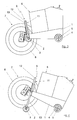
- the joint cutter according to the invention has a chassis frame 1, each with two front wheels 2, which are arranged on a front wheel axle 3, and two rear wheels 4, which are arranged on a rear wheel axle 5.
- the drive motor 6 and the necessary drive connections are basically known, which is why they will not be described in detail below.
- the drive motor 6 provides in the exemplary embodiment for the necessary advance of the joint cutter, so it drives one or more of the wheels 2, 4 at.
- the drive motor 6 also serves to drive a sawing device 7 with a rotating saw blade 8.
- the necessary mechanical connecting elements between the sawing device 7 and the saw blade 8 and the drive motor 6 are basically known and therefore not described in detail below.
- the sawing device 7 and the saw blade 8 are fixed with respect to their position on the chassis frame 1, ie the position of the sawing device 7 and the saw blade 8, regardless of whether the saw blade 8 is raised or in the working position, compared to the chassis frame 1 unchanged or "rigid".
- a "rigid" or unchanged position of the saw blade relative to the chassis frame 1 is to be understood as meaning that the saw blade 8 and necessary parts of the sawing device Turn 7 opposite the chassis frame 1.
- the sawing device 7 is pivotable from one longitudinal side of the chassis frame 1 to another longitudinal side
- a "rigid" or immovable attachment of the sawing device 7 or the saw blade 8 to the chassis frame 1 essentially means that the position of the sawing device 7 or of the saw blade 8 does not change to the chassis frame 1, when the saw blade 8 is moved from its working position to a raised position.
- the sawing device 7 and the saw blade 8 are arranged at a front end of the chassis frame 1 in such a way that the saw blade 8 is arranged laterally on the chassis frame 1 in the region of one of the front wheels 2. In general, it is advantageous if the saw blade 8 is arranged at a front end in the direction of travel of the chassis frame 1.
- the adjusting device 9 in this case has an associated with the chassis frame 1 linear guide device 10, at one end of the saw blade 8 associated barrel axis 3 is fixed.
- the linear guide device 10 allows a substantially vertical retraction and extension of the impeller axis 3 relative to the chassis frame 1.
- the adjusting device 9, a lifting device 11 which is arranged axially parallel to the linear guide device 10 and the lifting elements 12, 13 axially parallel to the linear guide device 10 on and are extendable.
- the running axis 3 is connected to the chassis frame 1 only or exclusively via the linear guide device 10 and the lifting device 11. Ie. the movement that the impeller axis 3 performs during retraction or extension of the chassis frame 1, is exclusively due to the movement of the linear guide device 10 and the lifting device eleventh
- the linear guide 14 engages at one end of the impeller axis 3 and the second linear guide 15 at the other end of the impeller axis 3 at.
- the first and the second linear guide 14, 15 are identical.
- the first linear guide 14 has two coaxially arranged and linearly displaceable guide elements 16, 17.
- a guide element is included as a guide pillar 16 and the other guide element as a guide rod 17 is formed.
- the guide column 16 is fixed or immovably connected to the chassis frame 1, for example by screwing, riveting or welding.
- the guide rod 17 is fixed to the impeller 3.
- the guide rod 17 is in the guide column 16 stable and linear or along the common axis movable.
- the guide column 16 has over the guide rod 17 has a smaller axial length.
- the lifting device 11 has two coaxially arranged and linearly movable to one another lifting elements 12, 13.
- the lifting device is designed as a hydraulic device 11.
- the lifting element 12 provides a Cylinder is, which is firmly connected in the embodiment with the chassis frame 1, for example by screwing, riveting or welding.
- the lifting element 13 is designed as a piston, which is in the cylinder 12 in response to an application of a hydraulic medium (not shown in detail) is displaceable.
- the piston 13 is fixed to the impeller axis 3.
- the piston 13 in the vicinity of one of the linear guides, in the embodiment of the first linear guide 14, set.
- the piston 13 is acted upon in such a way with a hydraulic medium, that the piston 13 extends downwardly from the chassis frame 1, when it is acted upon by a hydraulic medium.
- the lifting device 11 can also have a plurality of cylinder-piston units which are optionally supplied with hydraulic medium by one or more hydraulic devices.
- the cylinder-piston unit which represents the lifting device 11, and the first and second linear guide 14, 15, which by the guide columns 16 and the guide rod 17 are formed, arranged axially parallel to one another or extendable and retractable.
- the lifting device 11 and the first and the second linear guide 14, 15 penetrate the chassis frame 1 and are arranged substantially at right angles to the chassis frame or retracted and extended.
- the impeller axis 3 and the wheels 2 are removed from the chassis frame 1. In practice, this leads to that the chassis frame 1 is raised relative to the impeller axis 3 and against the wheels 2.
Landscapes
- Engineering & Computer Science (AREA)
- Mining & Mineral Resources (AREA)
- Mechanical Engineering (AREA)
- Architecture (AREA)
- Civil Engineering (AREA)
- Structural Engineering (AREA)
- Road Repair (AREA)
- Processing Of Stones Or Stones Resemblance Materials (AREA)
Applications Claiming Priority (1)
| Application Number | Priority Date | Filing Date | Title |
|---|---|---|---|
| DE200820011915 DE202008011915U1 (de) | 2008-09-08 | 2008-09-08 | Verfahrbarer Fugenschneider |
Publications (3)
| Publication Number | Publication Date |
|---|---|
| EP2161376A2 true EP2161376A2 (fr) | 2010-03-10 |
| EP2161376A3 EP2161376A3 (fr) | 2014-11-05 |
| EP2161376B1 EP2161376B1 (fr) | 2015-12-02 |
Family
ID=40076464
Family Applications (1)
| Application Number | Title | Priority Date | Filing Date |
|---|---|---|---|
| EP09164875.8A Active EP2161376B1 (fr) | 2008-09-08 | 2009-07-08 | Coupe-joint mobile |
Country Status (2)
| Country | Link |
|---|---|
| EP (1) | EP2161376B1 (fr) |
| DE (1) | DE202008011915U1 (fr) |
Cited By (5)
| Publication number | Priority date | Publication date | Assignee | Title |
|---|---|---|---|---|
| CN107053488A (zh) * | 2017-05-17 | 2017-08-18 | 泉州市海恩德机电科技发展有限公司 | 一种可移动和翻转的主轴结构 |
| CN107938485A (zh) * | 2017-11-25 | 2018-04-20 | 易亮 | 一种公路施工用路面切割机 |
| CN108894090A (zh) * | 2018-09-30 | 2018-11-27 | 周美兰 | 一种公路施工用路面切割机 |
| CN114790677A (zh) * | 2022-02-25 | 2022-07-26 | 张�浩 | 一种道路桥梁用路面水平切缝装置 |
| CN115075110A (zh) * | 2022-07-01 | 2022-09-20 | 王昱 | 一种避免出现切割死角的路面切缝机 |
Families Citing this family (5)
| Publication number | Priority date | Publication date | Assignee | Title |
|---|---|---|---|---|
| CN105401512B (zh) * | 2015-12-22 | 2017-09-26 | 湖南英格斯坦智能科技有限公司 | 路面切割机器人 |
| CN109049354B (zh) * | 2018-08-11 | 2020-06-12 | 武汉市城建工程有限公司 | 一种混凝土护栏的岔口改造装置 |
| CN110004830B (zh) * | 2019-03-11 | 2020-12-04 | 河北鸿森公路工程技术有限公司 | 一种桥梁桥面混凝土的缩缝切割密封一体化装置 |
| CN113981788A (zh) * | 2021-11-08 | 2022-01-28 | 张冰芳 | 一种道路桥梁施工用切缝机及其使用方法 |
| CN116163193B (zh) * | 2023-03-08 | 2024-01-16 | 连云港振江轨道交通设备有限公司 | 一种切割效率高的轨道自行路面切割装置 |
Citations (4)
| Publication number | Priority date | Publication date | Assignee | Title |
|---|---|---|---|---|
| DE8714999U1 (de) | 1987-11-11 | 1988-01-21 | Lissmac Maschinenbau GmbH, 7954 Bad Wurzach | Verfahrbarer Fugenschneider, insbesondere zur Herstellung von Schnitten in Straßendecken |
| DE4311778C2 (de) | 1993-04-09 | 1995-05-04 | Cedima Diamantwerkzeug Masch | Verfahrbarer Fugenschneider |
| DE29818892U1 (de) | 1998-10-23 | 1998-12-24 | Lissmac Maschinenbau und Diamantwerkzeuge GmbH, 88410 Bad Wurzach | Verfahrbarer Fugenschneider |
| DE20310916U1 (de) | 2003-07-16 | 2003-09-25 | Lissmac Maschinenbau und Diamantwerkzeuge GmbH, 88410 Bad Wurzach | Verfahrbarer Fugenschneider |
Family Cites Families (2)
| Publication number | Priority date | Publication date | Assignee | Title |
|---|---|---|---|---|
| JP3371254B2 (ja) * | 2000-02-10 | 2003-01-27 | 志賀産業株式会社 | 路面用カッター |
| US7487770B2 (en) * | 2006-01-14 | 2009-02-10 | Husqvarna Professional Outdoor Products Inc. | Assist for raise lower mechanism for a concrete saw |
-
2008
- 2008-09-08 DE DE200820011915 patent/DE202008011915U1/de not_active Expired - Lifetime
-
2009
- 2009-07-08 EP EP09164875.8A patent/EP2161376B1/fr active Active
Patent Citations (4)
| Publication number | Priority date | Publication date | Assignee | Title |
|---|---|---|---|---|
| DE8714999U1 (de) | 1987-11-11 | 1988-01-21 | Lissmac Maschinenbau GmbH, 7954 Bad Wurzach | Verfahrbarer Fugenschneider, insbesondere zur Herstellung von Schnitten in Straßendecken |
| DE4311778C2 (de) | 1993-04-09 | 1995-05-04 | Cedima Diamantwerkzeug Masch | Verfahrbarer Fugenschneider |
| DE29818892U1 (de) | 1998-10-23 | 1998-12-24 | Lissmac Maschinenbau und Diamantwerkzeuge GmbH, 88410 Bad Wurzach | Verfahrbarer Fugenschneider |
| DE20310916U1 (de) | 2003-07-16 | 2003-09-25 | Lissmac Maschinenbau und Diamantwerkzeuge GmbH, 88410 Bad Wurzach | Verfahrbarer Fugenschneider |
Cited By (5)
| Publication number | Priority date | Publication date | Assignee | Title |
|---|---|---|---|---|
| CN107053488A (zh) * | 2017-05-17 | 2017-08-18 | 泉州市海恩德机电科技发展有限公司 | 一种可移动和翻转的主轴结构 |
| CN107938485A (zh) * | 2017-11-25 | 2018-04-20 | 易亮 | 一种公路施工用路面切割机 |
| CN108894090A (zh) * | 2018-09-30 | 2018-11-27 | 周美兰 | 一种公路施工用路面切割机 |
| CN114790677A (zh) * | 2022-02-25 | 2022-07-26 | 张�浩 | 一种道路桥梁用路面水平切缝装置 |
| CN115075110A (zh) * | 2022-07-01 | 2022-09-20 | 王昱 | 一种避免出现切割死角的路面切缝机 |
Also Published As
| Publication number | Publication date |
|---|---|
| DE202008011915U1 (de) | 2008-11-27 |
| EP2161376A3 (fr) | 2014-11-05 |
| EP2161376B1 (fr) | 2015-12-02 |
Similar Documents
| Publication | Publication Date | Title |
|---|---|---|
| EP2161376B1 (fr) | Coupe-joint mobile | |
| EP2423076B1 (fr) | Dispositif de raccordement articulé de deux châssis de véhicules d'un engin | |
| AT505222B1 (de) | Formatkreissäge | |
| DE102011105556B4 (de) | Straßenbaumaschine | |
| EP1621682B1 (fr) | Appareil de transbordement. | |
| DE19536415C2 (de) | Scherschneidevorrichtung zur Verwendung mit einer Presse | |
| EP2532462A1 (fr) | Scie manuelle entraînée de manière motorisée | |
| EP2490849B1 (fr) | Machine-outil | |
| DE202013102190U1 (de) | Bandsäge mit einstellbarem Sägewinkel | |
| DE102007059065A1 (de) | Gabelstapler mit einem als Torsionsstütze vorgesehenen Fahrerschutzdach | |
| EP1920649A2 (fr) | Dispositif de taille haie | |
| EP3479678B1 (fr) | Dispositif formant scie destiné à la coupe de plantes | |
| EP1655450B1 (fr) | Appareil de forage | |
| DE102008033377A1 (de) | Sägeaggregat für vertikale Plattensäge | |
| DE102009024523A1 (de) | Bandsägemaschine mit einem Sägerahmen mit Sägeband | |
| DE3817005A1 (de) | Schweissmaschine zur herstellung von rahmen | |
| EP0812533A2 (fr) | Dispositif pour couper des haies et analogues | |
| EP1672165B1 (fr) | Appareil pour travaux de construction | |
| DE2747742A1 (de) | Selbsttaetig verschiebbares arbeitsgeraet fuer einen traktor | |
| EP3323283A1 (fr) | Bras ainsi qu'un appareil de travail à bras muni d'un tel bras | |
| DE102009056323B4 (de) | Haltevorrichtung für eine Maschine, insbesondere einen Laubentferner | |
| EP2295177A1 (fr) | Agrégat d'outil et machine d'extraction de rainures pour la fabrication de rainures ou d'évidements | |
| EP1403450B1 (fr) | Dispositif de deplacement | |
| EP1762131A1 (fr) | Appareil à faucher et/ou couper | |
| DE102005037389B4 (de) | Vielzweckarbeitsgerät |
Legal Events
| Date | Code | Title | Description |
|---|---|---|---|
| PUAI | Public reference made under article 153(3) epc to a published international application that has entered the european phase |
Free format text: ORIGINAL CODE: 0009012 |
|
| AK | Designated contracting states |
Kind code of ref document: A2 Designated state(s): AT BE BG CH CY CZ DE DK EE ES FI FR GB GR HR HU IE IS IT LI LT LU LV MC MK MT NL NO PL PT RO SE SI SK SM TR |
|
| PUAL | Search report despatched |
Free format text: ORIGINAL CODE: 0009013 |
|
| AK | Designated contracting states |
Kind code of ref document: A3 Designated state(s): AT BE BG CH CY CZ DE DK EE ES FI FR GB GR HR HU IE IS IT LI LT LU LV MC MK MT NL NO PL PT RO SE SI SK SM TR |
|
| RIC1 | Information provided on ipc code assigned before grant |
Ipc: E01C 23/09 20060101AFI20140930BHEP Ipc: B27B 5/10 20060101ALI20140930BHEP Ipc: B23D 45/02 20060101ALI20140930BHEP Ipc: B28D 1/04 20060101ALI20140930BHEP |
|
| 17P | Request for examination filed |
Effective date: 20150223 |
|
| RBV | Designated contracting states (corrected) |
Designated state(s): AT BE BG CH CY CZ DE DK EE ES FI FR GB GR HR HU IE IS IT LI LT LU LV MC MK MT NL NO PL PT RO SE SI SK SM TR |
|
| GRAP | Despatch of communication of intention to grant a patent |
Free format text: ORIGINAL CODE: EPIDOSNIGR1 |
|
| RIC1 | Information provided on ipc code assigned before grant |
Ipc: E01C 23/09 20060101AFI20150612BHEP Ipc: B28D 1/04 20060101ALI20150612BHEP Ipc: B23D 45/02 20060101ALI20150612BHEP Ipc: B27B 5/10 20060101ALI20150612BHEP |
|
| INTG | Intention to grant announced |
Effective date: 20150715 |
|
| GRAS | Grant fee paid |
Free format text: ORIGINAL CODE: EPIDOSNIGR3 |
|
| GRAA | (expected) grant |
Free format text: ORIGINAL CODE: 0009210 |
|
| AK | Designated contracting states |
Kind code of ref document: B1 Designated state(s): AT BE BG CH CY CZ DE DK EE ES FI FR GB GR HR HU IE IS IT LI LT LU LV MC MK MT NL NO PL PT RO SE SI SK SM TR |
|
| REG | Reference to a national code |
Ref country code: GB Ref legal event code: FG4D Free format text: NOT ENGLISH |
|
| REG | Reference to a national code |
Ref country code: AT Ref legal event code: REF Ref document number: 763693 Country of ref document: AT Kind code of ref document: T Effective date: 20151215 Ref country code: CH Ref legal event code: EP |
|
| REG | Reference to a national code |
Ref country code: IE Ref legal event code: FG4D Free format text: LANGUAGE OF EP DOCUMENT: GERMAN |
|
| REG | Reference to a national code |
Ref country code: DE Ref legal event code: R096 Ref document number: 502009011886 Country of ref document: DE |
|
| REG | Reference to a national code |
Ref country code: CH Ref legal event code: NV Representative=s name: CABINET ROLAND NITHARDT CONSEILS EN PROPRIETE , CH |
|
| REG | Reference to a national code |
Ref country code: SE Ref legal event code: TRGR |
|
| REG | Reference to a national code |
Ref country code: NL Ref legal event code: MP Effective date: 20160302 |
|
| REG | Reference to a national code |
Ref country code: LT Ref legal event code: MG4D |
|
| PG25 | Lapsed in a contracting state [announced via postgrant information from national office to epo] |
Ref country code: ES Free format text: LAPSE BECAUSE OF FAILURE TO SUBMIT A TRANSLATION OF THE DESCRIPTION OR TO PAY THE FEE WITHIN THE PRESCRIBED TIME-LIMIT Effective date: 20151202 Ref country code: NO Free format text: LAPSE BECAUSE OF FAILURE TO SUBMIT A TRANSLATION OF THE DESCRIPTION OR TO PAY THE FEE WITHIN THE PRESCRIBED TIME-LIMIT Effective date: 20160302 Ref country code: LT Free format text: LAPSE BECAUSE OF FAILURE TO SUBMIT A TRANSLATION OF THE DESCRIPTION OR TO PAY THE FEE WITHIN THE PRESCRIBED TIME-LIMIT Effective date: 20151202 Ref country code: HR Free format text: LAPSE BECAUSE OF FAILURE TO SUBMIT A TRANSLATION OF THE DESCRIPTION OR TO PAY THE FEE WITHIN THE PRESCRIBED TIME-LIMIT Effective date: 20151202 |
|
| PG25 | Lapsed in a contracting state [announced via postgrant information from national office to epo] |
Ref country code: NL Free format text: LAPSE BECAUSE OF FAILURE TO SUBMIT A TRANSLATION OF THE DESCRIPTION OR TO PAY THE FEE WITHIN THE PRESCRIBED TIME-LIMIT Effective date: 20151202 Ref country code: GR Free format text: LAPSE BECAUSE OF FAILURE TO SUBMIT A TRANSLATION OF THE DESCRIPTION OR TO PAY THE FEE WITHIN THE PRESCRIBED TIME-LIMIT Effective date: 20160303 Ref country code: PL Free format text: LAPSE BECAUSE OF FAILURE TO SUBMIT A TRANSLATION OF THE DESCRIPTION OR TO PAY THE FEE WITHIN THE PRESCRIBED TIME-LIMIT Effective date: 20151202 Ref country code: LV Free format text: LAPSE BECAUSE OF FAILURE TO SUBMIT A TRANSLATION OF THE DESCRIPTION OR TO PAY THE FEE WITHIN THE PRESCRIBED TIME-LIMIT Effective date: 20151202 Ref country code: FI Free format text: LAPSE BECAUSE OF FAILURE TO SUBMIT A TRANSLATION OF THE DESCRIPTION OR TO PAY THE FEE WITHIN THE PRESCRIBED TIME-LIMIT Effective date: 20151202 |
|
| PG25 | Lapsed in a contracting state [announced via postgrant information from national office to epo] |
Ref country code: IS Free format text: LAPSE BECAUSE OF FAILURE TO SUBMIT A TRANSLATION OF THE DESCRIPTION OR TO PAY THE FEE WITHIN THE PRESCRIBED TIME-LIMIT Effective date: 20151202 |
|
| REG | Reference to a national code |
Ref country code: FR Ref legal event code: PLFP Year of fee payment: 8 |
|
| PG25 | Lapsed in a contracting state [announced via postgrant information from national office to epo] |
Ref country code: IT Free format text: LAPSE BECAUSE OF FAILURE TO SUBMIT A TRANSLATION OF THE DESCRIPTION OR TO PAY THE FEE WITHIN THE PRESCRIBED TIME-LIMIT Effective date: 20151202 Ref country code: CZ Free format text: LAPSE BECAUSE OF FAILURE TO SUBMIT A TRANSLATION OF THE DESCRIPTION OR TO PAY THE FEE WITHIN THE PRESCRIBED TIME-LIMIT Effective date: 20151202 |
|
| PG25 | Lapsed in a contracting state [announced via postgrant information from national office to epo] |
Ref country code: IS Free format text: LAPSE BECAUSE OF FAILURE TO SUBMIT A TRANSLATION OF THE DESCRIPTION OR TO PAY THE FEE WITHIN THE PRESCRIBED TIME-LIMIT Effective date: 20160402 Ref country code: RO Free format text: LAPSE BECAUSE OF FAILURE TO SUBMIT A TRANSLATION OF THE DESCRIPTION OR TO PAY THE FEE WITHIN THE PRESCRIBED TIME-LIMIT Effective date: 20151202 Ref country code: PT Free format text: LAPSE BECAUSE OF FAILURE TO SUBMIT A TRANSLATION OF THE DESCRIPTION OR TO PAY THE FEE WITHIN THE PRESCRIBED TIME-LIMIT Effective date: 20160404 Ref country code: SK Free format text: LAPSE BECAUSE OF FAILURE TO SUBMIT A TRANSLATION OF THE DESCRIPTION OR TO PAY THE FEE WITHIN THE PRESCRIBED TIME-LIMIT Effective date: 20151202 Ref country code: SM Free format text: LAPSE BECAUSE OF FAILURE TO SUBMIT A TRANSLATION OF THE DESCRIPTION OR TO PAY THE FEE WITHIN THE PRESCRIBED TIME-LIMIT Effective date: 20151202 Ref country code: EE Free format text: LAPSE BECAUSE OF FAILURE TO SUBMIT A TRANSLATION OF THE DESCRIPTION OR TO PAY THE FEE WITHIN THE PRESCRIBED TIME-LIMIT Effective date: 20151202 |
|
| REG | Reference to a national code |
Ref country code: DE Ref legal event code: R097 Ref document number: 502009011886 Country of ref document: DE |
|
| PLBE | No opposition filed within time limit |
Free format text: ORIGINAL CODE: 0009261 |
|
| STAA | Information on the status of an ep patent application or granted ep patent |
Free format text: STATUS: NO OPPOSITION FILED WITHIN TIME LIMIT |
|
| PG25 | Lapsed in a contracting state [announced via postgrant information from national office to epo] |
Ref country code: DK Free format text: LAPSE BECAUSE OF FAILURE TO SUBMIT A TRANSLATION OF THE DESCRIPTION OR TO PAY THE FEE WITHIN THE PRESCRIBED TIME-LIMIT Effective date: 20151202 |
|
| 26N | No opposition filed |
Effective date: 20160905 |
|
| PG25 | Lapsed in a contracting state [announced via postgrant information from national office to epo] |
Ref country code: SI Free format text: LAPSE BECAUSE OF FAILURE TO SUBMIT A TRANSLATION OF THE DESCRIPTION OR TO PAY THE FEE WITHIN THE PRESCRIBED TIME-LIMIT Effective date: 20151202 |
|
| PG25 | Lapsed in a contracting state [announced via postgrant information from national office to epo] |
Ref country code: BE Free format text: LAPSE BECAUSE OF NON-PAYMENT OF DUE FEES Effective date: 20160731 |
|
| PG25 | Lapsed in a contracting state [announced via postgrant information from national office to epo] |
Ref country code: MC Free format text: LAPSE BECAUSE OF FAILURE TO SUBMIT A TRANSLATION OF THE DESCRIPTION OR TO PAY THE FEE WITHIN THE PRESCRIBED TIME-LIMIT Effective date: 20151202 |
|
| REG | Reference to a national code |
Ref country code: IE Ref legal event code: MM4A |
|
| REG | Reference to a national code |
Ref country code: FR Ref legal event code: PLFP Year of fee payment: 9 |
|
| PG25 | Lapsed in a contracting state [announced via postgrant information from national office to epo] |
Ref country code: IE Free format text: LAPSE BECAUSE OF NON-PAYMENT OF DUE FEES Effective date: 20160708 |
|
| PG25 | Lapsed in a contracting state [announced via postgrant information from national office to epo] |
Ref country code: LU Free format text: LAPSE BECAUSE OF NON-PAYMENT OF DUE FEES Effective date: 20160708 |
|
| PG25 | Lapsed in a contracting state [announced via postgrant information from national office to epo] |
Ref country code: HU Free format text: LAPSE BECAUSE OF FAILURE TO SUBMIT A TRANSLATION OF THE DESCRIPTION OR TO PAY THE FEE WITHIN THE PRESCRIBED TIME-LIMIT; INVALID AB INITIO Effective date: 20090708 Ref country code: CY Free format text: LAPSE BECAUSE OF FAILURE TO SUBMIT A TRANSLATION OF THE DESCRIPTION OR TO PAY THE FEE WITHIN THE PRESCRIBED TIME-LIMIT Effective date: 20151202 |
|
| PG25 | Lapsed in a contracting state [announced via postgrant information from national office to epo] |
Ref country code: MT Free format text: LAPSE BECAUSE OF FAILURE TO SUBMIT A TRANSLATION OF THE DESCRIPTION OR TO PAY THE FEE WITHIN THE PRESCRIBED TIME-LIMIT Effective date: 20151202 Ref country code: TR Free format text: LAPSE BECAUSE OF FAILURE TO SUBMIT A TRANSLATION OF THE DESCRIPTION OR TO PAY THE FEE WITHIN THE PRESCRIBED TIME-LIMIT Effective date: 20151202 Ref country code: MK Free format text: LAPSE BECAUSE OF FAILURE TO SUBMIT A TRANSLATION OF THE DESCRIPTION OR TO PAY THE FEE WITHIN THE PRESCRIBED TIME-LIMIT Effective date: 20151202 |
|
| REG | Reference to a national code |
Ref country code: FR Ref legal event code: PLFP Year of fee payment: 10 |
|
| PG25 | Lapsed in a contracting state [announced via postgrant information from national office to epo] |
Ref country code: BG Free format text: LAPSE BECAUSE OF FAILURE TO SUBMIT A TRANSLATION OF THE DESCRIPTION OR TO PAY THE FEE WITHIN THE PRESCRIBED TIME-LIMIT Effective date: 20151202 |
|
| PGFP | Annual fee paid to national office [announced via postgrant information from national office to epo] |
Ref country code: FR Payment date: 20200610 Year of fee payment: 12 |
|
| PGFP | Annual fee paid to national office [announced via postgrant information from national office to epo] |
Ref country code: GB Payment date: 20200724 Year of fee payment: 12 |
|
| PGFP | Annual fee paid to national office [announced via postgrant information from national office to epo] |
Ref country code: CH Payment date: 20201015 Year of fee payment: 12 |
|
| PGFP | Annual fee paid to national office [announced via postgrant information from national office to epo] |
Ref country code: AT Payment date: 20210720 Year of fee payment: 13 |
|
| REG | Reference to a national code |
Ref country code: CH Ref legal event code: PL |
|
| GBPC | Gb: european patent ceased through non-payment of renewal fee |
Effective date: 20210708 |
|
| PG25 | Lapsed in a contracting state [announced via postgrant information from national office to epo] |
Ref country code: LI Free format text: LAPSE BECAUSE OF NON-PAYMENT OF DUE FEES Effective date: 20210731 Ref country code: GB Free format text: LAPSE BECAUSE OF NON-PAYMENT OF DUE FEES Effective date: 20210708 Ref country code: CH Free format text: LAPSE BECAUSE OF NON-PAYMENT OF DUE FEES Effective date: 20210731 |
|
| PG25 | Lapsed in a contracting state [announced via postgrant information from national office to epo] |
Ref country code: FR Free format text: LAPSE BECAUSE OF NON-PAYMENT OF DUE FEES Effective date: 20210731 |
|
| REG | Reference to a national code |
Ref country code: AT Ref legal event code: MM01 Ref document number: 763693 Country of ref document: AT Kind code of ref document: T Effective date: 20220708 |
|
| PG25 | Lapsed in a contracting state [announced via postgrant information from national office to epo] |
Ref country code: AT Free format text: LAPSE BECAUSE OF NON-PAYMENT OF DUE FEES Effective date: 20220708 |
|
| P01 | Opt-out of the competence of the unified patent court (upc) registered |
Effective date: 20230519 |
|
| PGFP | Annual fee paid to national office [announced via postgrant information from national office to epo] |
Ref country code: SE Payment date: 20240722 Year of fee payment: 16 |
|
| PGFP | Annual fee paid to national office [announced via postgrant information from national office to epo] |
Ref country code: DE Payment date: 20250806 Year of fee payment: 17 |