EP2490849B1 - Machine-outil - Google Patents
Machine-outil Download PDFInfo
- Publication number
- EP2490849B1 EP2490849B1 EP10745606.3A EP10745606A EP2490849B1 EP 2490849 B1 EP2490849 B1 EP 2490849B1 EP 10745606 A EP10745606 A EP 10745606A EP 2490849 B1 EP2490849 B1 EP 2490849B1
- Authority
- EP
- European Patent Office
- Prior art keywords
- slotted
- stroke
- guide
- work tool
- power tool
- Prior art date
- Legal status (The legal status is an assumption and is not a legal conclusion. Google has not performed a legal analysis and makes no representation as to the accuracy of the status listed.)
- Not-in-force
Links
Images


Classifications
-
- B—PERFORMING OPERATIONS; TRANSPORTING
- B23—MACHINE TOOLS; METAL-WORKING NOT OTHERWISE PROVIDED FOR
- B23D—PLANING; SLOTTING; SHEARING; BROACHING; SAWING; FILING; SCRAPING; LIKE OPERATIONS FOR WORKING METAL BY REMOVING MATERIAL, NOT OTHERWISE PROVIDED FOR
- B23D49/00—Machines or devices for sawing with straight reciprocating saw blades, e.g. hacksaws
- B23D49/10—Hand-held or hand-operated sawing devices with straight saw blades
- B23D49/16—Hand-held or hand-operated sawing devices with straight saw blades actuated by electric or magnetic power or prime movers
- B23D49/162—Pad sawing devices
- B23D49/167—Pad sawing devices with means to adjust the guide plate or with means to adjust the plane in which the saw blade moves
Definitions
- the invention relates to a machine tool, in particular an electric motor driven jigsaw, according to the preamble of claim 1.
- a machine tool is EP 1 598 136 B1 refer to.
- Machine tools in the form of jigsaws with liftable driven saw blade which are operated in several modes, are known in various configurations.
- a rotatability of the lifting blade driven by the lifting movement is provided about a rotation axis parallel to the lifting axis and in which a guide body with a guide slot extending transversely to the lifting axis is provided on the saw blade, into which the crank pin of a crank disk mounted independently of the saw blade intervenes.
- the position of the guide link to the crank pin changes, which requires a certain clearance between these parts.
- such a solution also restricts the constructive freedom with respect to the rotary drive for the rotation of the saw blade about its stroke axis.
- the invention has for its object to design a trained especially as a jigsaw machine with hubbeweglich driven and rotatablymilandem work tool compact and still provide convenient access to the tool for the rotational adjustment and accurate and stable guidance of the tool without affecting the Hubantriebes despite the specver monoen leadership ,
- the supporting support of the link body of the cross thrust crank drive via the guide yoke against the housing avoids undesirable drive influences on the lifting driven working tool as well as corresponding reactions from the working tool on the cross thrust crank drive, which could affect the desired, possible backlash-free lifting guide for the working tool and a corresponding backlash-free operation of the cross thrust crank drive ,
- the rotatability of the working tool is made possible not only in structurally favorable manner by this configuration, but also without repercussions on the taking place via the cross-thrust crank drive the working tool.
- the guide yoke and the link body rotatably supported each other if necessary, be integrally formed, so that even for the link body despite the plane offset to the yoke ultimately a quasi-immediate support is given to the housing.
- the pivot also offers particularly favorable conditions for access to the necessary for the working tool rotary drive to the working tool.
- This also in machine tools that are designed as jigsaws and where the serving as a working tool, driven liftable saw blade in the so-called Pendelhub shall in the direction of the saw blade plane is pivotally superimposed driven to the linear actuator, since in such a configuration, the required, transverse to the lifting axis support of the working tool , Or a lifting rod carrying the working tool, can be articulated directly on the pivot pin via a corresponding pivot connection, such as a pivot pin.
- An axially spaced access to the guide yoke of the rotary drive on the working tool, in particular in its design as a saw blade can be realized in the described basic construction in an advantageous manner via a pivot pin axially spaced Drehabstützung, which is preferably formed by a housing side supported bearing, the one Having based on the rotatability about the lifting axis supporting sliding guide for the non-circular cross-section, in particular rectangular cross-section, having lifting rod.
- this sliding guide is preferably designed as extending in pendulum direction slot guide with given to the lifting rod excess in pendulum direction.
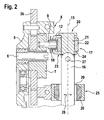
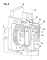
- the Fig. 1 to 4 illustrate, reduced to the essentials, drive and guide for the working tool 1 of a machine tool 2, which is designed as a jigsaw 3 and which has a jigsaw blade 4 as a working tool 1.
- a machine tool 2 which is designed as a jigsaw 3 and which has a jigsaw blade 4 as a working tool 1.
- jigsaws In connection with the generally known construction of jigsaws, one has vorzusilen the solution shown in the figures for drive and leadership embedded in the structure of the jigsaw, which is supported by a foot plate to the workpiece and enclosed in the drive and guide for the working tool in the housing side , are arranged with respect to the working direction front part of the machine housing, as for example, the above-mentioned in the prior art documents show.
- FIG. 1 to 4 the illustrations go according to Fig. 1 to 4 from a support frame 5, which is connected to a housing, not shown, against which the crank disk 7 of a cross thrust crank drive 8 is supported, whose crank pin 9 carries a bearing 10 and engages in the guide slot 11 of a guide body 12 via this bearing 10.
- the link body 12 with the guide slot 11 extends in a plane 13 which is the same direction to a plane 14 in which the lifting axis 15 of the working tool 1 forming saw blade 4 extends, wherein the plane 13 is offset transversely to the lifting axis 15.
- the mass balance serves a arranged on an eccentric collar of the crank disc 7, lying in the transition from the support frame 5 on the crank disc 7 disc-shaped balance weight 36th
- lifting rod 16 In the connection of the jigsaw blade 4 to the cross thrust crank drive 8 extending in the direction of the lifting axis 15 lifting rod 16 is provided in the known manner, on the one hand expires in a receptacle for the respective saw blade 4 and on the other hand supported against a guide yoke 17 and this guide yoke 17 in Direction of the lifting plane 14 slidably guided to the housing is fixed.
- the guide relative to the housing takes place on the housing side supported sliding guides 18, in which the guide yoke 17 extends over laterally projecting lugs 19, between which the central support 20 of the lifting rod 16, and thus the saw blade 4 to the guide yoke 17.
- the central support 20 is formed in the embodiment by a pivot pin 21 which passes through the guide yoke 17 in a central, provided in its central part 22 opening.
- the guide yoke 17 extends with its laterally projecting lugs 19 and these receiving sliding guides 18 in the lifting plane 14, which is parallel to the lifting plane 13, in which the guide slot 11 of the link body extends.
- the link body 12 is provided with a spacer 23 bridging the distance between the lifting planes 13 and 14, against which the guide yoke 17 is supported in the region of its middle part 22.
- the boom 23 is formed by two spaced apart in the direction of the lifting axis 15 fork arms 24, which are provided transversely to the extension direction of the guide slot 11 opposite each other on the crank body 12.
- the gate body 12 and the guide yoke 17 separate parts, which are connected via the pivot pin 21, which carries the saw blade 4 via the lifting rod 16 and is in the drive. In principle, however, it is also within the scope of the invention to connect the guide yoke 17 integrally with the link body 12.
- the support 25 preferably has a enclosing to a Unrundquerrough having lifting rod 16 provided bearing body 26, via which the lifting rod 16 in the stroke direction as well as transversely to the working plane of the lifting rod 16 carried by the saw blade 4, and thus also transversely to the lifting axis 15 is guided.
- the relevant drive is not shown in the embodiment, but can be done in the form shown in the prior art - is the Lifting rod 16 connected to a transverse to the lifting axis 15 pivot axis 27 with the pivot pin 21.
- the transverse guidance of the lifting direction in the pendulum direction 28 adjustable lifting rod at a non-circular profile of the lifting rod 16 parallel to the pendulum direction 28 extending flanks via a slot guide 29 in the bearing 26, wherein the slot guide 29 in the direction of travel 28 to the cross section of the lifting rod 16 corresponding Excessive.
- the for the rotation of the working tool 1, in particular in the form of the saw blade 4, required rotary drive, in the Fig. 3 and 4 symbolically indicated by the arrow 30, can preferably attack on the pivot pin 21 or on the bearing 26, so that in this respect already given components can also be used to transfer the introduced via the rotary drive torque to the working tool 1.
- the pivot pin 21 offers many opportunities for the attack of a corresponding rotary drive.
- Fig. 3 is a related structural solution for a rotary drive 30 schematically indicated at 31.
- the symbolically indicated by the arrow 30 rotary actuator is in the embodiment according to Fig. 4 as a rotary drive 39 on the pivot pin 21 at.
- the pivot pin 21 is provided with a laterally projecting lever arm 32.
- the lever arm 32 engages a coaxial with the pivot pin 21 fixed rotary arm 33 of a connecting member 34.
- the rotary arm 33 extends in the direction of the lifting axis 15 and has a running in the direction of the lifting axis 15 backdrop 35, so that a fixed to the housing, not shown drive regardless of the lifting movement for the rotary drive of the working tool 1 can be used.
- the embodiment according to Fig. 4 illustrates that even with access of the rotary drive on the pivot pin 21 a simple design of the corresponding drive connection is possible.
- a acting on the connecting member 34, symbolized by the arrow 30 rotary drive can also engage a lying in the direction of the lifting axis 15 drive pin 38 of the connecting member 34, wherein an associated drive motor in the axial extension of the drive pin 38 fixed at axially displaceable connection to the drive pin 38 is provided can be. Also, a radial access of a housing side supported drive on the drive pin is possible, so that different drive concepts 38 can be provided with the same basic structure.
Landscapes
- Engineering & Computer Science (AREA)
- Mechanical Engineering (AREA)
- Sawing (AREA)
- Transmission Devices (AREA)
Claims (12)
- Machine-outil, en particulier scie sauteuse (3) entraînée par un moteur électrique, comprenant un outil de travail (1) réglable en rotation autour de son axe de levage (15) situé dans un plan de levage (14), lequel outil de travail est entraîné dans la direction de levage par le biais d'une commande à bielle manivelle (8) dont le maneton de bielle (9) vient en prise dans une coulisse de guidage (11), s'étendant transversalement à l'axe de levage (15), d'un corps de coulisse (12) levable conjointement avec l'outil de travail (1) dans la direction d'étendue de l'axe de levage (15), dont la coulisse de guidage (11) et l'axe de levage (15) de l'outil de travail (1) s'étendent dans des plans de levage (13, 14) décalés l'un par rapport à l'autre, orientés dans la même direction, en particulier parallèles, caractérisée en ce que l'outil de travail (1) est maintenu rotatif par le biais d'un étrier de guidage (17) qui porte le corps de coulisse (12) avec la coulisse de guidage (11) et qui est guidé à coulissement du côté du boîtier dans la direction d'étendue du plan de levage (14) contenant l'axe de levage (15) de l'outil de travail (1).
- Machine-outil selon la revendication 1, caractérisée en ce que l'étrier de guidage (17) et le corps de coulisse (12) sont supportés l'un sur l'autre de manière solidaire en rotation.
- Machine-outil selon la revendication 1, caractérisée en ce que l'étrier de guidage (17) et le corps de coulisse (12) forment des composants séparés ou sont réalisés d'une seule pièce.
- Machine-outil selon la revendication 1, caractérisée en ce que l'étrier de guidage (17) et le corps de coulisse (12) sont supportés l'un sur l'autre de manière mobile en rotation autour de l'axe de levage (15) de l'outil de travail (1).
- Machine-outil selon l'une quelconque des revendications précédentes, caractérisée en ce que le corps de coulisse (12) est connecté par le biais d'un bras en porte-à-faux (23) à l'étrier de guidage (17).
- Machine-outil selon la revendication 5, caractérisée en ce que l'étrier de guidage (17) est supporté dans la direction de levage entre des bras de fourche (24) du bras en porte-à-faux (23) du corps de coulisse (12).
- Machine-outil selon les revendications 4 à 6, caractérisée en ce que l'outil de travail (1), le corps de coulisse (12) et l'étrier de guidage (17) sont connectés de manière rotative autour de l'axe de levage (15) de l'outil de travail (1) et sont supportés l'un contre l'autre par le biais d'une goupille (21).
- Machine-outil selon l'une quelconque des revendications précédentes, caractérisée en ce que l'outil de travail (1) est connecté à la goupille (21) autour d'un axe de pivotement (27) s'étendant transversalement à l'axe de levage (15).
- Machine-outil selon la revendication 7 ou 8, caractérisée en ce que l'outil de travail (1) peut être ajusté dans sa direction de travail par le biais de la goupille (21).
- Machine-outil selon la revendication 9, caractérisée en ce que l'entraînement en rotation (flèche 30) pour l'outil de travail (1) vient en prise sur la goupille (21).
- Machine-outil selon la revendication 9 ou 10, caractérisée en ce que la goupille (21) est connectée avec un bras pivotant (33) situé de manière décalée latéralement par rapport à l'axe de levage (15) et s'étendant dans la direction de l'axe de levage (15), sur lequel vient en prise l'entraînement en rotation (39) guidé sur coulisse et déplaçable longitudinalement dans la direction de l'axe de levage (15).
- Machine-outil selon l'une quelconque des revendications précédentes, caractérisée en ce que l'outil de travail (1) est guidé dans la direction de son axe de levage (15) de manière décalée par rapport à l'étrier de guidage (17) suivant un mouvement de levage dans un palier pivotant (26), sur lequel vient en prise l'entraînement en rotation (flèche 30) pour l'outil de travail (1).
Applications Claiming Priority (3)
| Application Number | Priority Date | Filing Date | Title |
|---|---|---|---|
| DE102009045954 | 2009-10-23 | ||
| DE102009046374A DE102009046374A1 (de) | 2009-10-23 | 2009-11-04 | Werkzeugmaschine |
| PCT/EP2010/062208 WO2011047904A1 (fr) | 2009-10-23 | 2010-08-23 | Machine-outil |
Publications (2)
| Publication Number | Publication Date |
|---|---|
| EP2490849A1 EP2490849A1 (fr) | 2012-08-29 |
| EP2490849B1 true EP2490849B1 (fr) | 2013-05-29 |
Family
ID=43796664
Family Applications (1)
| Application Number | Title | Priority Date | Filing Date |
|---|---|---|---|
| EP10745606.3A Not-in-force EP2490849B1 (fr) | 2009-10-23 | 2010-08-23 | Machine-outil |
Country Status (5)
| Country | Link |
|---|---|
| EP (1) | EP2490849B1 (fr) |
| CN (1) | CN102596469B (fr) |
| DE (1) | DE102009046374A1 (fr) |
| RU (1) | RU2543115C2 (fr) |
| WO (1) | WO2011047904A1 (fr) |
Families Citing this family (6)
| Publication number | Priority date | Publication date | Assignee | Title |
|---|---|---|---|---|
| DE102010018685B4 (de) * | 2010-04-29 | 2015-09-24 | Uwe Hartmann | Dekupiersäge |
| US9573207B2 (en) | 2013-05-09 | 2017-02-21 | Makita Corporation | Reciprocating cutting tool |
| WO2019177753A1 (fr) | 2018-03-16 | 2019-09-19 | Milwaukee Electric Tool Corporation | Serre-lame pour outil électrique |
| USD887806S1 (en) | 2018-04-03 | 2020-06-23 | Milwaukee Electric Tool Corporation | Jigsaw |
| EP3774148B1 (fr) | 2018-04-03 | 2025-02-12 | Milwaukee Electric Tool Corporation | Scie sauteuse |
| DE102018206874A1 (de) * | 2018-05-04 | 2019-11-07 | Robert Bosch Gmbh | Stichsägengehäuse |
Family Cites Families (9)
| Publication number | Priority date | Publication date | Assignee | Title |
|---|---|---|---|---|
| SU501868A1 (ru) * | 1974-06-21 | 1976-02-05 | Горьковский Автомобильный Завод | Пневматическа пила |
| US4272996A (en) * | 1979-06-19 | 1981-06-16 | Black & Decker Inc. | Scotch yoke having a curved track |
| US4262420A (en) * | 1979-12-14 | 1981-04-21 | The Singer Company | Crosshead for sabre saws and sabre saws incorporating same |
| DE3702670A1 (de) | 1986-12-18 | 1988-08-11 | Licentia Gmbh | Stichsaege mit durch eine kreuzschubkurbel erzeugter hubbewegung des stoessels |
| US5724741A (en) * | 1996-03-12 | 1998-03-10 | Milwaukee Electric Tool Corporation | Reciprocating saw with pivoting shoe |
| JP3710697B2 (ja) | 2000-09-19 | 2005-10-26 | 株式会社マキタ | 往復動切断工具 |
| GB2393934A (en) * | 2002-10-07 | 2004-04-14 | Black & Decker Inc | A reciprocating saw with two eccentrics |
| DE602004002572T2 (de) | 2004-05-18 | 2007-07-12 | Black & Decker Inc., Newark | Anordnung eines Ausgangsstössels und motorisiertes Werkzeug mit einer solchen Anordnung |
| RU55324U1 (ru) * | 2006-03-13 | 2006-08-10 | Общество с ограниченной ответственностью "Инструментальная компания ЭНКОР" | Настольный электрический лобзик |
-
2009
- 2009-11-04 DE DE102009046374A patent/DE102009046374A1/de not_active Withdrawn
-
2010
- 2010-08-23 RU RU2012120902/02A patent/RU2543115C2/ru not_active IP Right Cessation
- 2010-08-23 WO PCT/EP2010/062208 patent/WO2011047904A1/fr not_active Ceased
- 2010-08-23 CN CN201080047855.XA patent/CN102596469B/zh active Active
- 2010-08-23 EP EP10745606.3A patent/EP2490849B1/fr not_active Not-in-force
Also Published As
| Publication number | Publication date |
|---|---|
| EP2490849A1 (fr) | 2012-08-29 |
| DE102009046374A1 (de) | 2011-04-28 |
| WO2011047904A1 (fr) | 2011-04-28 |
| RU2012120902A (ru) | 2013-11-27 |
| CN102596469A (zh) | 2012-07-18 |
| CN102596469B (zh) | 2015-02-11 |
| RU2543115C2 (ru) | 2015-02-27 |
Similar Documents
| Publication | Publication Date | Title |
|---|---|---|
| DE102007039580B4 (de) | Antriebsmechanismus für einen Motorfuchsschwanz | |
| EP2490849B1 (fr) | Machine-outil | |
| DE4108982B4 (de) | Taumelscheibenantrieb | |
| EP2139654B1 (fr) | Machine-outil entraînée par un moteur | |
| EP2161376B1 (fr) | Coupe-joint mobile | |
| EP0175643B1 (fr) | Perceuse sur montant avec colonne de guidage | |
| EP1320437B1 (fr) | Scie equipee d'un mecanisme de guidage d'outil comprenant des elements de guidage qui peuvent etre regles en fonction de l'epaisseur de l'outil | |
| EP2384251A2 (fr) | Machine-outil à moteur | |
| EP3038779B1 (fr) | Engrenage de scie alternative | |
| DE112012003859T5 (de) | Hin- und hergehendes Werkzeug | |
| EP2384252A1 (fr) | Machine-outil actionnée par moteur | |
| EP2532462A1 (fr) | Scie manuelle entraînée de manière motorisée | |
| EP1955802B1 (fr) | Scie à métaux, en particulier scie sauteuse | |
| DE102008001769A1 (de) | Werkzeugmaschine, insbesondere handgehaltene Werkzeugmaschine | |
| EP0478823B1 (fr) | Machine à roder | |
| EP2029304B1 (fr) | Machine à scier à mouvement alternatif dotée d'une lame de scie avec dispositif de guidage | |
| WO2009138267A1 (fr) | Machine-outil, en particulier machine-outil portative | |
| DE2839449A1 (de) | Strangbrennschneidmaschine | |
| DE19804706B4 (de) | Handgeführte Stichsägemaschine | |
| DE971561C (de) | Landwirtschaftliches Anbaugeraet fuer Traktoren | |
| DE1502970B2 (de) | Flachmesser-Saumschere | |
| WO2010076080A2 (fr) | Machine-outil à moteur | |
| WO2010063503A1 (fr) | Machine-outil avec un dispositif de guidage pour un outil | |
| WO2009138272A1 (fr) | Machine-outil, en particulier machine-outil portative | |
| DE4203890C1 (en) | Hand-held cutter for sheet metal etc. - has electric micro-motor with eccentric CAM connected to cutting blade shaft |
Legal Events
| Date | Code | Title | Description |
|---|---|---|---|
| PUAI | Public reference made under article 153(3) epc to a published international application that has entered the european phase |
Free format text: ORIGINAL CODE: 0009012 |
|
| 17P | Request for examination filed |
Effective date: 20120523 |
|
| AK | Designated contracting states |
Kind code of ref document: A1 Designated state(s): AL AT BE BG CH CY CZ DE DK EE ES FI FR GB GR HR HU IE IS IT LI LT LU LV MC MK MT NL NO PL PT RO SE SI SK SM TR |
|
| DAX | Request for extension of the european patent (deleted) | ||
| GRAP | Despatch of communication of intention to grant a patent |
Free format text: ORIGINAL CODE: EPIDOSNIGR1 |
|
| GRAS | Grant fee paid |
Free format text: ORIGINAL CODE: EPIDOSNIGR3 |
|
| GRAA | (expected) grant |
Free format text: ORIGINAL CODE: 0009210 |
|
| AK | Designated contracting states |
Kind code of ref document: B1 Designated state(s): AL AT BE BG CH CY CZ DE DK EE ES FI FR GB GR HR HU IE IS IT LI LT LU LV MC MK MT NL NO PL PT RO SE SI SK SM TR |
|
| REG | Reference to a national code |
Ref country code: GB Ref legal event code: FG4D Free format text: NOT ENGLISH |
|
| REG | Reference to a national code |
Ref country code: CH Ref legal event code: EP |
|
| REG | Reference to a national code |
Ref country code: AT Ref legal event code: REF Ref document number: 614047 Country of ref document: AT Kind code of ref document: T Effective date: 20130615 |
|
| REG | Reference to a national code |
Ref country code: IE Ref legal event code: FG4D Free format text: LANGUAGE OF EP DOCUMENT: GERMAN |
|
| REG | Reference to a national code |
Ref country code: DE Ref legal event code: R096 Ref document number: 502010003485 Country of ref document: DE Effective date: 20130801 |
|
| REG | Reference to a national code |
Ref country code: LT Ref legal event code: MG4D |
|
| PG25 | Lapsed in a contracting state [announced via postgrant information from national office to epo] |
Ref country code: NO Free format text: LAPSE BECAUSE OF FAILURE TO SUBMIT A TRANSLATION OF THE DESCRIPTION OR TO PAY THE FEE WITHIN THE PRESCRIBED TIME-LIMIT Effective date: 20130829 Ref country code: SE Free format text: LAPSE BECAUSE OF FAILURE TO SUBMIT A TRANSLATION OF THE DESCRIPTION OR TO PAY THE FEE WITHIN THE PRESCRIBED TIME-LIMIT Effective date: 20130529 Ref country code: FI Free format text: LAPSE BECAUSE OF FAILURE TO SUBMIT A TRANSLATION OF THE DESCRIPTION OR TO PAY THE FEE WITHIN THE PRESCRIBED TIME-LIMIT Effective date: 20130529 Ref country code: GR Free format text: LAPSE BECAUSE OF FAILURE TO SUBMIT A TRANSLATION OF THE DESCRIPTION OR TO PAY THE FEE WITHIN THE PRESCRIBED TIME-LIMIT Effective date: 20130830 Ref country code: SI Free format text: LAPSE BECAUSE OF FAILURE TO SUBMIT A TRANSLATION OF THE DESCRIPTION OR TO PAY THE FEE WITHIN THE PRESCRIBED TIME-LIMIT Effective date: 20130529 Ref country code: PT Free format text: LAPSE BECAUSE OF FAILURE TO SUBMIT A TRANSLATION OF THE DESCRIPTION OR TO PAY THE FEE WITHIN THE PRESCRIBED TIME-LIMIT Effective date: 20130930 Ref country code: IS Free format text: LAPSE BECAUSE OF FAILURE TO SUBMIT A TRANSLATION OF THE DESCRIPTION OR TO PAY THE FEE WITHIN THE PRESCRIBED TIME-LIMIT Effective date: 20130929 Ref country code: LT Free format text: LAPSE BECAUSE OF FAILURE TO SUBMIT A TRANSLATION OF THE DESCRIPTION OR TO PAY THE FEE WITHIN THE PRESCRIBED TIME-LIMIT Effective date: 20130529 Ref country code: ES Free format text: LAPSE BECAUSE OF FAILURE TO SUBMIT A TRANSLATION OF THE DESCRIPTION OR TO PAY THE FEE WITHIN THE PRESCRIBED TIME-LIMIT Effective date: 20130909 |
|
| REG | Reference to a national code |
Ref country code: NL Ref legal event code: VDEP Effective date: 20130529 |
|
| PG25 | Lapsed in a contracting state [announced via postgrant information from national office to epo] |
Ref country code: BG Free format text: LAPSE BECAUSE OF FAILURE TO SUBMIT A TRANSLATION OF THE DESCRIPTION OR TO PAY THE FEE WITHIN THE PRESCRIBED TIME-LIMIT Effective date: 20130829 Ref country code: PL Free format text: LAPSE BECAUSE OF FAILURE TO SUBMIT A TRANSLATION OF THE DESCRIPTION OR TO PAY THE FEE WITHIN THE PRESCRIBED TIME-LIMIT Effective date: 20130529 Ref country code: HR Free format text: LAPSE BECAUSE OF FAILURE TO SUBMIT A TRANSLATION OF THE DESCRIPTION OR TO PAY THE FEE WITHIN THE PRESCRIBED TIME-LIMIT Effective date: 20130529 |
|
| PG25 | Lapsed in a contracting state [announced via postgrant information from national office to epo] |
Ref country code: LV Free format text: LAPSE BECAUSE OF FAILURE TO SUBMIT A TRANSLATION OF THE DESCRIPTION OR TO PAY THE FEE WITHIN THE PRESCRIBED TIME-LIMIT Effective date: 20130529 |
|
| PG25 | Lapsed in a contracting state [announced via postgrant information from national office to epo] |
Ref country code: SK Free format text: LAPSE BECAUSE OF FAILURE TO SUBMIT A TRANSLATION OF THE DESCRIPTION OR TO PAY THE FEE WITHIN THE PRESCRIBED TIME-LIMIT Effective date: 20130529 Ref country code: DK Free format text: LAPSE BECAUSE OF FAILURE TO SUBMIT A TRANSLATION OF THE DESCRIPTION OR TO PAY THE FEE WITHIN THE PRESCRIBED TIME-LIMIT Effective date: 20130529 Ref country code: CZ Free format text: LAPSE BECAUSE OF FAILURE TO SUBMIT A TRANSLATION OF THE DESCRIPTION OR TO PAY THE FEE WITHIN THE PRESCRIBED TIME-LIMIT Effective date: 20130529 Ref country code: EE Free format text: LAPSE BECAUSE OF FAILURE TO SUBMIT A TRANSLATION OF THE DESCRIPTION OR TO PAY THE FEE WITHIN THE PRESCRIBED TIME-LIMIT Effective date: 20130529 |
|
| BERE | Be: lapsed |
Owner name: ROBERT BOSCH G.M.B.H. Effective date: 20130831 |
|
| PG25 | Lapsed in a contracting state [announced via postgrant information from national office to epo] |
Ref country code: NL Free format text: LAPSE BECAUSE OF FAILURE TO SUBMIT A TRANSLATION OF THE DESCRIPTION OR TO PAY THE FEE WITHIN THE PRESCRIBED TIME-LIMIT Effective date: 20130529 Ref country code: RO Free format text: LAPSE BECAUSE OF FAILURE TO SUBMIT A TRANSLATION OF THE DESCRIPTION OR TO PAY THE FEE WITHIN THE PRESCRIBED TIME-LIMIT Effective date: 20130529 Ref country code: IT Free format text: LAPSE BECAUSE OF FAILURE TO SUBMIT A TRANSLATION OF THE DESCRIPTION OR TO PAY THE FEE WITHIN THE PRESCRIBED TIME-LIMIT Effective date: 20130529 |
|
| PLBE | No opposition filed within time limit |
Free format text: ORIGINAL CODE: 0009261 |
|
| STAA | Information on the status of an ep patent application or granted ep patent |
Free format text: STATUS: NO OPPOSITION FILED WITHIN TIME LIMIT |
|
| PG25 | Lapsed in a contracting state [announced via postgrant information from national office to epo] |
Ref country code: MC Free format text: LAPSE BECAUSE OF FAILURE TO SUBMIT A TRANSLATION OF THE DESCRIPTION OR TO PAY THE FEE WITHIN THE PRESCRIBED TIME-LIMIT Effective date: 20130529 |
|
| 26N | No opposition filed |
Effective date: 20140303 |
|
| REG | Reference to a national code |
Ref country code: IE Ref legal event code: MM4A |
|
| PG25 | Lapsed in a contracting state [announced via postgrant information from national office to epo] |
Ref country code: BE Free format text: LAPSE BECAUSE OF NON-PAYMENT OF DUE FEES Effective date: 20130831 |
|
| REG | Reference to a national code |
Ref country code: DE Ref legal event code: R097 Ref document number: 502010003485 Country of ref document: DE Effective date: 20140303 |
|
| PG25 | Lapsed in a contracting state [announced via postgrant information from national office to epo] |
Ref country code: IE Free format text: LAPSE BECAUSE OF NON-PAYMENT OF DUE FEES Effective date: 20130823 |
|
| REG | Reference to a national code |
Ref country code: CH Ref legal event code: PL |
|
| GBPC | Gb: european patent ceased through non-payment of renewal fee |
Effective date: 20140823 |
|
| PG25 | Lapsed in a contracting state [announced via postgrant information from national office to epo] |
Ref country code: CH Free format text: LAPSE BECAUSE OF NON-PAYMENT OF DUE FEES Effective date: 20140831 Ref country code: LI Free format text: LAPSE BECAUSE OF NON-PAYMENT OF DUE FEES Effective date: 20140831 |
|
| PG25 | Lapsed in a contracting state [announced via postgrant information from national office to epo] |
Ref country code: SM Free format text: LAPSE BECAUSE OF FAILURE TO SUBMIT A TRANSLATION OF THE DESCRIPTION OR TO PAY THE FEE WITHIN THE PRESCRIBED TIME-LIMIT Effective date: 20130529 |
|
| PG25 | Lapsed in a contracting state [announced via postgrant information from national office to epo] |
Ref country code: MT Free format text: LAPSE BECAUSE OF FAILURE TO SUBMIT A TRANSLATION OF THE DESCRIPTION OR TO PAY THE FEE WITHIN THE PRESCRIBED TIME-LIMIT Effective date: 20130529 Ref country code: TR Free format text: LAPSE BECAUSE OF FAILURE TO SUBMIT A TRANSLATION OF THE DESCRIPTION OR TO PAY THE FEE WITHIN THE PRESCRIBED TIME-LIMIT Effective date: 20130529 Ref country code: CY Free format text: LAPSE BECAUSE OF FAILURE TO SUBMIT A TRANSLATION OF THE DESCRIPTION OR TO PAY THE FEE WITHIN THE PRESCRIBED TIME-LIMIT Effective date: 20130529 |
|
| PG25 | Lapsed in a contracting state [announced via postgrant information from national office to epo] |
Ref country code: LU Free format text: LAPSE BECAUSE OF NON-PAYMENT OF DUE FEES Effective date: 20130823 Ref country code: GB Free format text: LAPSE BECAUSE OF NON-PAYMENT OF DUE FEES Effective date: 20140823 Ref country code: HU Free format text: LAPSE BECAUSE OF FAILURE TO SUBMIT A TRANSLATION OF THE DESCRIPTION OR TO PAY THE FEE WITHIN THE PRESCRIBED TIME-LIMIT; INVALID AB INITIO Effective date: 20100823 Ref country code: MK Free format text: LAPSE BECAUSE OF FAILURE TO SUBMIT A TRANSLATION OF THE DESCRIPTION OR TO PAY THE FEE WITHIN THE PRESCRIBED TIME-LIMIT Effective date: 20130529 |
|
| REG | Reference to a national code |
Ref country code: FR Ref legal event code: PLFP Year of fee payment: 7 |
|
| REG | Reference to a national code |
Ref country code: AT Ref legal event code: MM01 Ref document number: 614047 Country of ref document: AT Kind code of ref document: T Effective date: 20150823 |
|
| PG25 | Lapsed in a contracting state [announced via postgrant information from national office to epo] |
Ref country code: AT Free format text: LAPSE BECAUSE OF NON-PAYMENT OF DUE FEES Effective date: 20150823 |
|
| PGFP | Annual fee paid to national office [announced via postgrant information from national office to epo] |
Ref country code: FR Payment date: 20160825 Year of fee payment: 7 |
|
| REG | Reference to a national code |
Ref country code: FR Ref legal event code: ST Effective date: 20180430 |
|
| PG25 | Lapsed in a contracting state [announced via postgrant information from national office to epo] |
Ref country code: FR Free format text: LAPSE BECAUSE OF NON-PAYMENT OF DUE FEES Effective date: 20170831 |
|
| PG25 | Lapsed in a contracting state [announced via postgrant information from national office to epo] |
Ref country code: AL Free format text: LAPSE BECAUSE OF FAILURE TO SUBMIT A TRANSLATION OF THE DESCRIPTION OR TO PAY THE FEE WITHIN THE PRESCRIBED TIME-LIMIT Effective date: 20130529 |
|
| REG | Reference to a national code |
Ref country code: DE Ref legal event code: R084 Ref document number: 502010003485 Country of ref document: DE |
|
| PGFP | Annual fee paid to national office [announced via postgrant information from national office to epo] |
Ref country code: DE Payment date: 20241024 Year of fee payment: 15 |
|
| REG | Reference to a national code |
Ref country code: DE Ref legal event code: R119 Ref document number: 502010003485 Country of ref document: DE |