EP2163347A2 - Dispositif variable adaptable destiné à retirer des injecteurs - Google Patents
Dispositif variable adaptable destiné à retirer des injecteurs Download PDFInfo
- Publication number
- EP2163347A2 EP2163347A2 EP09010146A EP09010146A EP2163347A2 EP 2163347 A2 EP2163347 A2 EP 2163347A2 EP 09010146 A EP09010146 A EP 09010146A EP 09010146 A EP09010146 A EP 09010146A EP 2163347 A2 EP2163347 A2 EP 2163347A2
- Authority
- EP
- European Patent Office
- Prior art keywords
- support
- cylinder head
- rails
- adjusting
- rail
- Prior art date
- Legal status (The legal status is an assumption and is not a legal conclusion. Google has not performed a legal analysis and makes no representation as to the accuracy of the status listed.)
- Withdrawn
Links
Images


Classifications
-
- B—PERFORMING OPERATIONS; TRANSPORTING
- B25—HAND TOOLS; PORTABLE POWER-DRIVEN TOOLS; MANIPULATORS
- B25B—TOOLS OR BENCH DEVICES NOT OTHERWISE PROVIDED FOR, FOR FASTENING, CONNECTING, DISENGAGING, OR HOLDING
- B25B27/00—Hand tools, specially adapted for fitting together or separating parts or objects whether or not involving some deformation, not otherwise provided for
- B25B27/02—Hand tools, specially adapted for fitting together or separating parts or objects whether or not involving some deformation, not otherwise provided for for connecting objects by press fit or detaching same
- B25B27/023—Hand tools, specially adapted for fitting together or separating parts or objects whether or not involving some deformation, not otherwise provided for for connecting objects by press fit or detaching same using screws
-
- B—PERFORMING OPERATIONS; TRANSPORTING
- B25—HAND TOOLS; PORTABLE POWER-DRIVEN TOOLS; MANIPULATORS
- B25B—TOOLS OR BENCH DEVICES NOT OTHERWISE PROVIDED FOR, FOR FASTENING, CONNECTING, DISENGAGING, OR HOLDING
- B25B27/00—Hand tools, specially adapted for fitting together or separating parts or objects whether or not involving some deformation, not otherwise provided for
- B25B27/0035—Hand tools, specially adapted for fitting together or separating parts or objects whether or not involving some deformation, not otherwise provided for for motor-vehicles
-
- B—PERFORMING OPERATIONS; TRANSPORTING
- B25—HAND TOOLS; PORTABLE POWER-DRIVEN TOOLS; MANIPULATORS
- B25B—TOOLS OR BENCH DEVICES NOT OTHERWISE PROVIDED FOR, FOR FASTENING, CONNECTING, DISENGAGING, OR HOLDING
- B25B27/00—Hand tools, specially adapted for fitting together or separating parts or objects whether or not involving some deformation, not otherwise provided for
- B25B27/02—Hand tools, specially adapted for fitting together or separating parts or objects whether or not involving some deformation, not otherwise provided for for connecting objects by press fit or detaching same
-
- F—MECHANICAL ENGINEERING; LIGHTING; HEATING; WEAPONS; BLASTING
- F02—COMBUSTION ENGINES; HOT-GAS OR COMBUSTION-PRODUCT ENGINE PLANTS
- F02M—SUPPLYING COMBUSTION ENGINES IN GENERAL WITH COMBUSTIBLE MIXTURES OR CONSTITUENTS THEREOF
- F02M61/00—Fuel-injectors not provided for in groups F02M39/00 - F02M57/00 or F02M67/00
- F02M61/14—Arrangements of injectors with respect to engines; Mounting of injectors
-
- F—MECHANICAL ENGINEERING; LIGHTING; HEATING; WEAPONS; BLASTING
- F02—COMBUSTION ENGINES; HOT-GAS OR COMBUSTION-PRODUCT ENGINE PLANTS
- F02M—SUPPLYING COMBUSTION ENGINES IN GENERAL WITH COMBUSTIBLE MIXTURES OR CONSTITUENTS THEREOF
- F02M2200/00—Details of fuel-injection apparatus, not otherwise provided for
- F02M2200/85—Mounting of fuel injection apparatus
- F02M2200/855—Mounting of fuel injection apparatus using clamp elements or fastening means, e.g. bolts or screws
Definitions
- the invention relates to a device for extracting injectors of a cylinder head, one of which is provided on the cylinder head supporting crossbar and a cross member in operative connection, axially adjustable drawbar existing pulling device is provided, the pull rod can be brought into train connection with the injector.
- injection nozzles for fuel injection into the cylinder chamber, which are arranged in the cylinder head.
- injection nozzles are seated in corresponding receiving bores and in the fully assembled state project beyond the cylinder head axially outwards (above).
- injection nozzle has a head part, via which the injection nozzle can be controlled electronically.
- This head part is further provided with a fuel supply line, so that a corresponding arranged in the head part valve for intermittent fuel injection is electronically controlled.
- devices for pulling out of injection nozzles have become known, in which for removing the injector, the head part is first to remove. After removal of the head part either an external thread in the outer end region of the injection nozzle or an internal thread is freely accessible.
- a kind of cross-beam or web as an abutment, which can be coupled with an axially adjustable tie rod.
- This cross-beam forms together with the drawbar and possibly other components a kind of pulling device, through which the injection nozzle can be pulled out.
- this pull rod can be brought into train connection with the injection nozzle either via its external thread or its internal thread.
- this tie rod In its outwardly projecting end region, this tie rod also has an adjusting thread on which a draw nut is also screwed. This pull nut serves only as an abutment for transmitting the adjusting movement of the individual cylinder on the pull rod. Accordingly, when the single cylinder is activated, the pull rod is moved axially outward and the injector coupled to the pull rod is pulled out.
- a disadvantage of this construction is also that in particular the support tube adapted precisely to the surface design of the cylinder head in the surrounding area of the injection nozzle must be in order to achieve a fully coaxial pulling force on the ejection nozzle. This in turn means that the entire construction must be adapted to the shape of a cylinder head and thus can not be variably used for any cylinder head.
- a pull rod is provided, which can be coupled via a coupling thread optionally with an external thread and / or an internal thread of the extracting the injector.
- To pull the pull rod can also be coupled to a hydraulic cylinder, which is designed as a so-called. Hollow piston cylinder.
- the pull rod penetrate the "hollow piston" of the hydraulic cylinder with a threaded portion to the outside, so that a corresponding tension nut can be screwed onto this threaded portion.
- the tension nut is tightened until it rests externally on the hydraulic cylinder or its hollow piston.
- a lifting movement is now effected, so that the pull rod is pulled out axially via the tension nut and thus the injection nozzle moves with it.
- the table must be adapted in its design specifically to the training and design of a cylinder head to use this device with differently shaped cylinder heads can.
- the invention has for its object to design a device for removing injectors of a cylinder head in such a way that they vary for cylinder heads differently Design, in particular different surface design in the valve cover, can be used.
- the object is achieved according to the invention together with the features of the preamble of claim 1, characterized in that two guide rails are provided, on which the cross-beam in different, aligned to the respective extracted injector working positions can be arranged and that the guide rails on the cylinder head in a predetermined, substantially at right angles to each extending injection nozzle extending alignment can be positioned on the cylinder head and that each rail are each associated with supporting bolts, via which the adjusting rails are supported directly or indirectly at a predetermined distance on the top side of the cylinder head.
- a device which can be used variably on cylinder heads of different design.
- two adjusting rails are provided, which in particular can be mounted or mounted variably on or on a cylinder head.
- a cross-beam is supported axially, which in turn is variably arranged in different orientations on the adjusting rails.
- the positioning rails thereby run essentially at right angles to the injection nozzle to be removed in each case in a common plane, so that tilting is reliably prevented.
- these adjusting rails are arranged at the same vertical distance from the injection nozzle on the cylinder head, so that the cross-beam is oriented accordingly perpendicular to the injector to be pulled out.
- the adjusting rails can be attached to the cylinder head at a predetermined distance therefrom, so that in particular the cross-beam with its pulling device can always be arranged in an optimum position relative to an injection nozzle to be pulled out.
- the cross-beam is variably positionable both in the transverse direction and in the longitudinal direction of the adjusting rails, whereby the device according to the invention can be variably adjusted to the respective position of the injectors used in a cylinder head.
- the adjusting rails each have in different positions arranged through holes and / or a longitudinal slot which extends approximately over the entire length of the adjusting rail and that the support pin in one of the through holes or in the adjusting slot of the associated control rail intervention.
- the arrangement of the through holes can be adapted to different configurations of cylinder heads, so that the adjusting rails can be used on cylinder heads with different positioning of internal threads. These internal threads are usually provided on the upper side of a cylinder, for example, to attach a valve cover close to the cylinder head.
- the provision of longitudinal slots allows in particular an approximately arbitrary longitudinal displacement and fixation of the adjusting rails on the support bolts on a cylinder head, so that in particular even with shorter rails all required Positions of an injection nozzle on a cylinder head can be reached.
- the support bolts can accordingly be provided according to claim 3 with threaded pins, with which the support bolts are fixedly screwed into the provided for mounting the valve cover internal thread of the cylinder head.
- the support bolts can be designed such that the guide rails can also be placed without having to remove the valve cover. Accordingly, the normal mounting screws of the valve cover are replaced by the support bolts in a simple manner, so that they form a solid support for the guide rails.
- two (or more) support bolts are provided here for each rail.
- the two adjusting rails are, as claimed in claim 1, aligned substantially parallel to the top of the cylinder head.
- these guide rails can run parallel to one another or else at an angle to one another in a common "horizontal plane" in the mounted state. Accordingly, these adjusting rails are variable to any shape of a cylinder head via appropriate choice of the length of the support bolts used.
- the support bolts are provided in their threaded studs axially opposite end portions with mounting pins, which are plugged through the longitudinal slot of the respective associated rail and through which the rail is fixed to the support pin fixed.
- mounting nuts can be provided according to claim 5, which are screwed onto a threaded portion of the respective mounting pin of the support bolt. This allows after attaching a support pin or the support bolt on the cylinder head and an adjustment of the guide rails in the longitudinal direction in a simple manner by the mounting nuts are easily solved and tightened relative to the cylinder head when setting the desired position of the guide rails again.
- the cross-beam can be arranged by this fixed arrangement of the adjusting rails on the support bolts in the projecting beyond the support bolts areas of the control rail without tilting the rails during application of tensile forces.
- the support bolts are provided with threaded pins, with which the support bolts are fixedly connected to the support rails.
- Such an embodiment may be required if the internal threads of the cylinder head are difficult to access for screwing in the support bolts.
- the mounting rails are usually used with the valve cover removed and are on the corresponding sealing surface of the cylinder head for the valve cover. Since, with the valve cover removed, the support bolts bear against the internal thread of the cylinder head in the immediate vicinity of the screw thread of the valve cover, there is at least the danger here that deformation of the sealing surface in this surrounding area will occur at extremely high pull-out forces.
- the support rails are provided on the underside of the cylinder head with a support element which extends over the entire length of the support rail and is formed of a plastic. This is achieved on the one hand by the mounting rail itself an extremely high stability and on the other hand prevents the sealing surfaces of the cylinder head for the valve cover can be damaged.
- the cross-beam forms two radially extending support arms, between which a central internal thread is arranged and that with the internal thread a drawbar having traction device is fixedly coupled. Due to this configuration, in particular by the support arms, the cross-beam can be placed in an extremely simple manner on the mounted on the cylinder head guide rails.
- the central internal thread can be provided for coupling different traction devices.
- the support arms of the cross-beam are provided with openings, through which the cross-beam on the rails by means of screw in their set target position is fixed fixed.
- This embodiment causes a stabilization of the entire device in its correctly attached to the cylinder head state.
- the apertures of the cross-beam are formed as slots or longitudinal slots open on one side, so that the cross-beam is freely adjustable transversely to the guide rails and thus can be brought in a simple manner in the desired desired position.
- the pull rod may be formed as a tensile spindle, as is already partially known from the prior art.
- this tension spindle has a coupling thread in its one end region, with which the tension spindle can be coupled fixedly with the injection nozzle to be pulled out.
- This design of the pull rod as a pull spindle and as the actual draw device or device allows an extremely cost-effective production.
- this may be further provided for this purpose according to claim 11, that in the internal thread of the crossmember an adapter ring is screwed, in which for axial support of the tension spindle a thrust bearing is sunk and that a pull nut is provided, which on a the adapter ring and the thrust bearing protruding Adjusting thread of the tension spindle is screwed and through which the required tensile forces can be applied to the tension spindle.
- This construction allows, in particular due to the proposed thrust bearing, extremely low tightening forces during the extraction process of an injection nozzle.
- the provided adapter ring can be used in the crossbeam also any other suitable pulling device.
- the pull rod may also be part of a hydraulic cylinder.
- the pull rod also has a coupling thread in its one end region, with which the pull spindle can be coupled fixedly with the injection nozzle to be pulled out.
- the hydraulic cylinder in turn is in turn coupled to the internal thread of the cross-beam, so that here also an easily manageable traction device is provided.
- by providing a very large tensile forces are applied to a hydraulic cylinder, so that even extremely tight injectors can be easily pulled out.
- the cross-beam can also have an extremely simple and inexpensive design.
- this cross-beam can be formed according to claim 13 of a perforated U-steel.
- This U-steel has a central through hole, with which the traction device (traction spindle with adapter, hydraulic cylinder) can be coupled.
- the pull rod is provided in its the coupling thread opposite end portion with an axially projecting drive hexagon.
- Such a configuration allows in particular the secure and fixed screwing or screwing the drawbar on the upper end of a correspondingly designed and provided with an internal or external thread injection nozzle.
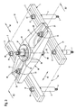
- Fig. 1 shows various components of a device according to the invention in a perspective exploded view. So are in Fig. 1 two guide rails 1 and 2 can be seen, which each have an approximately over the entire length extending longitudinal slot 3 and 4 respectively. Each of the guide rails 1, 2 are assigned to two support pins 5 and 6, wherein for the control rail 2, only one support pin 6 is shown.
- the support bolts 5 and 6 are in Fig. 1 shown shortened. Furthermore, the support bolts 5 and 6 each have in their lower end region an axially projecting threaded pin 7 or 8. With these threaded pins 7 and 8, the support bolts 5 and 6 fixed, for example, in the internal thread of a cylinder head can be screwed. Such internal threads are generally used for fixed fixation of a valve cover to a cylinder head. That is, for mounting the support bolts 5 and 6 on a cylinder head, first, the mounting bolts of the valve cover are to be removed. The length of the threaded pins 7 and 8 can be designed such that the valve cover for mounting the support bolts 5 and 6 can remain on the cylinder head.
- the support pins 5 and 6 In order to screw the support pins 5 and 6 fixed in the corresponding internal thread, they can each be provided with a corresponding drive hexagon 9 and 10 respectively.
- the support bolts 5 and 6 In axial extension to the respective drive hexagon 9 and 10 and in the axially opposite end region to the respective threaded pin, the support bolts 5 and 6 are each provided with a mounting pin 11 and 12, respectively formed radially tapered and through the longitudinal slot 3 and 4 of the each associated adjusting rail 1 and 2 are plugged through.
- the mounting pins 11 and 12 have in their outer axial end region in each case a threaded portion 13 and 14, respectively, on each of which a mounting nut 15 and 16 can be screwed.
- a cross-beam 20 can be seen, which forms two diametrically opposite support arms 21 and 22.
- These support arms 21 and 22 have a substantially U-shaped cross-section, wherein in the horizontally extending web portion 23 and 24 respectively an outwardly open to the end region of the respective support arm 21 and 22 slot-like opening 25 and 26 is provided.
- the cross-beam 20 forms a connecting portion 27, which is provided with a central internal thread 28.
- FIG. 1 two fixing screws 29 and 30 recognizable.
- These fixing screws 29 and 30 can be inserted through the respective longitudinal slot 3 or 4 of the respectively associated adjusting rail 1 or 2 and can be brought into engagement with the openings 25 and 26 of the supporting arms 21 and 22 of the crosspiece 20.
- corresponding retaining nuts 31 and 32 are provided, which are each screwed onto a threaded portion 33 and 34 of the respective fixing screw 29 and 30 respectively.
- U-disks 35 and 36 are provided.
- the internal thread 28 of the connecting portion 27 serves to receive a traction device, which has different configurations can have.
- a traction device which has different configurations can have.
- a tension spindle 40 which has a coupling thread 41 in its lower end region.
- the traction spindle 40 has a corresponding drive hexagon 42 in its upper end region opposite the coupling thread 41.
- the traction spindle 40 forms an adjusting thread 43 in the area between the coupling thread 41 and the drive hexagon 42, which extends approximately to the coupling thread 41.
- an adapter ring 44 recognizable, which is provided on the underside with a radially tapered external thread 45. With this external thread of the adapter ring 44 in the internal thread 28 of the connecting portion 27 of the crossbeam 20 is fixed screwed.
- the adapter ring 44 forms on the upper side a central depression 46 into which a thrust bearing 47 can be inserted.
- This thrust bearing 47 is held captive by means of a retaining ring 48 in the recess 46, wherein the locking ring 48 can be inserted in a corresponding circumferential receiving groove 49 under bias.
- a pull nut 50 can be seen, which is correspondingly screwed onto the adjusting thread 43 of the tension spindle 40 for applying the required axial forces.
- This pull nut 50 forms a radially projecting gutter 51, with which the pull nut 50 is supported on the upper side of the thrust bearing 47 during operation. Furthermore, the pull nut 50 in the axial extension of the gutter 51 down toward a guide cylinder 52, with which the pull nut 50 fits into the axial thrust bearing 47.
- Fig. 3 shows the assembled state of an embodiment of a device 55 according to the invention, which consists of the components described and illustrated in the drawing figures 1 and 2.
- the two adjusting rails 1 and 2 are substantially parallel to each other and lie in a common plane 56.
- the support bolts 5 are inserted with their threaded portions 13 through the longitudinal slot 3 of the guide rail 1 therethrough.
- the associated, designed as a collar nuts mounting nuts 15 are screwed.
- the two support pins 5 are arranged substantially perpendicular to the associated control rail 1 extending fixed to this rail 1.
- the distance of the support pin 5 from each other or their position in the adjusting slot 3 of the guide rail 1 is determined by the position of the screw thread on a cylinder head, in which the support pin 5 with its threaded pin 7 can be screwed.
- Fig. 3 It can be seen that the support bolts 6 are inserted with their threaded portions 14 through the adjusting slot 4 of the adjusting rail 2 through and held stationary by means of mounting nuts 16 on the adjusting rail 2.
- Fig. 3 is only the left support pin 6 completely shown. Also, this support pin 6 is screwed with its threaded pin 8 in a corresponding internal thread of a cylinder head, as has already been described above.
- the cross-beam 20 is with its two support arms 21 and 22 mutually on the two adjusting rails 1 and 2.
- the two in Fig. 3 not completely visible fixing screws 29 and 30 are inserted through both the respective longitudinal slot 3 and 4 of the associated rail 1 and 2 as well as through the respectively associated opening 25 and 26 of the respectively associated or resting support arm 21 and 22 through.
- Fig. 3 recognizable retaining nuts 31 and 32 thus the cross-beam 20 is held in a preset position fixed to the guide rails 1 and 2.
- the adapter ring 44 is screwed into the connecting portion 27 of the cross-beam 20, while the tensioning nut 50 is screwed onto the adjusting spindle 40 protruding through the adapter ring 44.
- the tension nut 50 is, as already in Fig. 2 described, inserted into the adapter ring 44 and is supported axially on the thrust bearing 47 Fig. 2 from.
- the two adjusting rails 1 and 2 depending on the configuration of the cylinder head to which the support pins 5 and 6 are to be set, freely adjusted according to the length of their adjusting slots 3 and 4 in the direction of the double arrow 60 and placed in the required position become.
- To align the tension spindle 40 on a nozzle to be pulled off the crosshead can be adjusted with dissolved retaining nuts 31 and 32 on the one hand in the direction of the double arrow 61 in the direction of their openings 25 and 26 and by corresponding displacement of the fixing screws 29 and 30 along the adjusting slots 3 and 4 also the longitudinal central axis 62 are rotated in the direction of the double arrow 63.
- the entire device 55 in a simple and effective manner to the circumstances, in particular to the shape and design of a cylinder head, adaptable. It is provided that also support bolts 5 and 6 of different lengths can be used to possibly reach arranged in different levels internal thread of a cylinder head, at the same time the guide rails 1 and 2 in the in Fig. 3 remain in common plane 56. This ensures that the tension spindle 40 can be aligned coaxially with an injection nozzle to be pulled out.
- adjusting slots 3 and 4 may be provided in each of the adjusting rails 1 and 2, a plurality of through holes, which may each have different distances from each other, to thereby also ensure a variable use.
- Fig. 4 shows a vertical section IV-IV Fig. 3 by the fully assembled device 55 in its attached to a cylinder head 65 shown only schematically state. It can be seen that the support bolts 5 and 6 are screwed with their threaded pins 7 and 8 in corresponding internal threads 66 and 67. According to the present embodiment Fig. 4 are between the cylinder head 65 and the two support bolts 5 and 6 still U-disks 68 and 69 used for a "height compensation". Furthermore, a likewise only schematically illustrated injection nozzle 71 is inserted into a receiving bore 70 of the cylinder head 65. This injection nozzle 71 has a head part 72, which is provided with an internal thread 73. In this internal thread 73, the tension spindle 40 is inserted with its coupling thread 41 in the present embodiment of the device 55.
- the tension spindle 40 can also be provided with a corresponding internal thread, with which the tension spindle 40 can be coupled with such a designed injection nozzle 71.
- Fig. 4 recognizable that the two adjusting rails 1 and 2 are placed on the respectively associated support pin 5 and 6.
- the guide rails 1 and 2 run in the representation of Fig. 4 parallel to each other, but ultimately depends on the arrangement of the internal threads 66 and 67 of the cylinder head. D. h. That the guide rails 1 and 2, depending on the arrangement of such internal threads 66 and 67 can also run obliquely to each other.
- the two fixing screws 29 and 30 protrude through both the longitudinal slots 3 and 4 and the openings 25 and 26 of the two support arms 21 and 22 of the crosspiece 20 and are fixed by means of the retaining nuts 31 and 32 on the crosspiece 20.
- the inserted U-disks 35 and 36 are made Fig. 4 recognizable.
- the adapter ring 44 is screwed with its external thread 45 in the internal thread 28 of the connecting portion 27 of the crossbeam 20 fixed.
- the thrust bearing 47 is inserted into the recess 46 of the adapter ring 44 and is held securely by the retaining ring 48.
- the tension nut 50 is screwed onto the adjusting thread 43 and is supported axially downwards on the thrust bearing 47. It is easily conceivable that upon actuation of the tension nut 50, the tensioning spindle is pulled in the direction of the arrow 75 and, accordingly, the injection nozzle 71 is pulled out of its receiving bore 70.
- the pulling spindle 40 can be aligned as desired with each injector 71 to be pulled out coaxially with it.
- Fig. 5 shows a perspective view of a support rail 80, which is provided on the upper side with two Einschraubgewinden 81 and 82.
- a support rail 80 is assigned to each rail 1 and 2 with their support pins 5 and 6, wherein the support pins 5 and 6 with their threaded pins 7 and 8 in the screw 81 and 82 are screwed.
- Such a support rail 80 is preferably used when a support in the region of the internal thread of a cylinder head is not possible and the entire device 55 is preferably put on the support rails 80, for example on the sealing surface of a valve cover.
- a support member 83 may be provided which, for example, by means of two mounting screws 84 on the underside of the mounting rail 80 can be fastened. Accordingly, the support rail 80 on the underside two internal threads 85.
- Fig. 6 shows a vertical section VI-VI Fig. 4 by the device according to the invention with mounted mounting rail 80. It is in Fig. 6 the crossbeam 20, the fixing screw 21 together with the retaining nut 31 and the positioning rail 1 recognizable.
- the two support pins 5 are screwed with their threaded pin 7 fixed in the screw-in thread 81 and 82 of the support rail 80. Furthermore, the support bolts 5 with the adjusting rail 1 via the mounting pin 11 and the associated mounting nuts 15 fixed in connection.
- the support element 83 is fixedly mounted on the mounting rail 80 on the underside of the two mounting screws 84. there the mounting screws 84 sunk in the support element 83 are arranged so that they can cause any damage to a flat sealing surface of a cylinder head.
- Fig. 7 shows a further simplified embodiment of a cross-beam 90, which is formed from a U-steel 91.
- the transverse web 94 connecting the two U-legs 92 and 93 has corresponding to the configuration of the two support arms 21 and 22 of the cross-beam 20 Fig. 1 also two slit-like, outwardly open breakthroughs 95 and 96, respectively. According to the operation of the apertures 25 and 26, the same applies to the apertures 95 and 96 as described above.
- a through hole 97 is arranged in the transverse web 94, which serves for example for receiving the adapter ring 44, as in particular from the vertical section of the cross-beam 90 from Fig. 8 is apparent.
- a mounting ring 98 is provided, which has an internal thread 99. With this internal thread 99 of the mounting ring 98 can be screwed onto the external thread 45 of the adapter ring 44, as can be seen from Fig. 8 is apparent.
- this mounting ring 98 of the adapter ring 44 is held stationary on the crosspiece 94 of the cross member 90.
- the guide rails 1 and 2 may also be part of a support frame (not explicitly shown in the drawing).
- the support frame may be designed to be adjustable, so that the lateral distance of the guide rails is further adaptable according to the configuration of a cylinder head.
- a one-piece, rigid Training such a support frame conceivable.
- the support frame may have a plurality of differently arranged holes and / or longitudinal slots, in particular for variable recording of the support bolts.
Landscapes
- Engineering & Computer Science (AREA)
- Mechanical Engineering (AREA)
- Chemical & Material Sciences (AREA)
- Combustion & Propulsion (AREA)
- General Engineering & Computer Science (AREA)
- Fuel-Injection Apparatus (AREA)
- On-Site Construction Work That Accompanies The Preparation And Application Of Concrete (AREA)
Applications Claiming Priority (1)
| Application Number | Priority Date | Filing Date | Title |
|---|---|---|---|
| DE200820012338 DE202008012338U1 (de) | 2008-09-16 | 2008-09-16 | Variabel anpassbare Vorrichtung zum Ausziehen von Einspritzdüsen |
Publications (2)
| Publication Number | Publication Date |
|---|---|
| EP2163347A2 true EP2163347A2 (fr) | 2010-03-17 |
| EP2163347A3 EP2163347A3 (fr) | 2010-11-17 |
Family
ID=40031258
Family Applications (1)
| Application Number | Title | Priority Date | Filing Date |
|---|---|---|---|
| EP09010146A Withdrawn EP2163347A3 (fr) | 2008-09-16 | 2009-08-06 | Dispositif variable adaptable destiné à retirer des injecteurs |
Country Status (2)
| Country | Link |
|---|---|
| EP (1) | EP2163347A3 (fr) |
| DE (1) | DE202008012338U1 (fr) |
Cited By (11)
| Publication number | Priority date | Publication date | Assignee | Title |
|---|---|---|---|---|
| US20120174363A1 (en) * | 2011-01-06 | 2012-07-12 | Wei Nan Shen | Tool device for dismantling joint |
| EP2581172A1 (fr) | 2011-10-11 | 2013-04-17 | Werkzeug Pichler GmbH & Co. KG | Face d'appui |
| GB2502784A (en) * | 2012-06-06 | 2013-12-11 | Centrifuge Ind Co Ltd | Stand for supporting an engine injector disassembling apparatus and an injector disassembling assembly comprising the same |
| CN103692399A (zh) * | 2012-09-28 | 2014-04-02 | 海洋王照明科技股份有限公司 | 灯具开盖装置 |
| CN103737545B (zh) * | 2014-01-13 | 2015-12-30 | 安徽江淮汽车股份有限公司 | 一种用于装配双离合器封油盖的工装 |
| EP3323552A1 (fr) | 2016-11-22 | 2018-05-23 | Wallmek i Kungälv AB | Outil de démontage amélioré |
| USD850226S1 (en) | 2016-11-22 | 2019-06-04 | Wallmek i Kungälv AB | Tool yoke |
| US10532450B2 (en) | 2016-11-22 | 2020-01-14 | Wallmek i Kungälv AB | Tool kit for vehicles |
| CN111546287A (zh) * | 2020-06-15 | 2020-08-18 | 常州博瑞电力自动化设备有限公司 | 用于阀串的待检器件更换装置及其使用方法 |
| CN113172577A (zh) * | 2021-04-28 | 2021-07-27 | 山东送变电工程有限公司 | 用于牵引机绳轮拆、装的工装及其使用方法 |
| CN115234419A (zh) * | 2022-07-07 | 2022-10-25 | 广西玉柴机器股份有限公司 | 一种限制喷油器接口角度的调整装置 |
Families Citing this family (11)
| Publication number | Priority date | Publication date | Assignee | Title |
|---|---|---|---|---|
| ITMO20090049A1 (it) | 2009-02-27 | 2010-08-28 | Go Vo Ni Srl | Attrezzatura per l'estrazione di iniettori di motori diesel. |
| JP5487992B2 (ja) * | 2010-01-25 | 2014-05-14 | 三菱自動車工業株式会社 | インジェクタ引き抜き工具 |
| DE102010042581B4 (de) * | 2010-10-18 | 2013-10-17 | Bayerische Motoren Werke Aktiengesellschaft | Werkzeug zur Montage und Demontage eines Injektors einer Brennkraftmaschine |
| NL1038816C2 (nl) * | 2011-05-17 | 2012-11-20 | Jacob Matheus Maria Broek | Verstuivertrekker. |
| DE102012104515B4 (de) * | 2012-05-24 | 2014-08-28 | Centrifuge Industrial Co., Ltd. | Stützgestell für eine Einspritzdüsen-Demontagevorrichtung für Motoren und dieses Stützgestell umfassendes Einspritzdüsendemontagemodul |
| DE102014209668B4 (de) | 2014-05-21 | 2016-08-25 | Bayerische Motoren Werke Aktiengesellschaft | Werkzeug zur Demontage eines Injektors einer Brennkraftmaschine |
| EP3235597B1 (fr) * | 2016-04-21 | 2019-03-13 | Pichler Werkzeug GmbH & Co KG | Face d'appui |
| DE102017106600A1 (de) * | 2017-03-28 | 2018-10-04 | Andreas Szabados | Vorrichtung zum Lösen von in einer Matrize festsitzenden Patronenhülsen |
| CN108422382B (zh) * | 2018-05-08 | 2023-11-21 | 河南森源电气股份有限公司 | 一种断路器小喷口紧固装置 |
| CN110712176A (zh) * | 2019-09-26 | 2020-01-21 | 沪东重机有限公司 | 一种大功率柴油机喷油器的取出装置及快速取出方法 |
| CN111376212A (zh) * | 2020-04-26 | 2020-07-07 | 重庆大唐国际武隆水电开发有限公司 | 一种重型螺母旋拧辅助工具 |
Citations (3)
| Publication number | Priority date | Publication date | Assignee | Title |
|---|---|---|---|---|
| US2883741A (en) | 1957-03-27 | 1959-04-28 | William M Yerkes | Diesel injection nozzle puller |
| US5784783A (en) | 1996-04-18 | 1998-07-28 | Carpenter; Donald L. | Method of removing an injector sleeve |
| DE202004006602U1 (de) | 2004-04-23 | 2004-09-09 | Weitner, Werner | Vorrichtung zum Ziehen einer Einspritzdüse |
Family Cites Families (3)
| Publication number | Priority date | Publication date | Assignee | Title |
|---|---|---|---|---|
| GB907046A (en) * | 1960-06-28 | 1962-10-03 | John Henry Chown | An improved appliance for removing the cylinder heads of internal combustion engines |
| DE10215103A1 (de) * | 2002-04-05 | 2003-07-17 | Bayerische Motoren Werke Ag | Vorrichtung zum Montieren und Demontieren von Ventilen |
| US6871390B1 (en) * | 2003-09-16 | 2005-03-29 | Tony Liu | Spring detachment device for automobile |
-
2008
- 2008-09-16 DE DE200820012338 patent/DE202008012338U1/de not_active Expired - Lifetime
-
2009
- 2009-08-06 EP EP09010146A patent/EP2163347A3/fr not_active Withdrawn
Patent Citations (3)
| Publication number | Priority date | Publication date | Assignee | Title |
|---|---|---|---|---|
| US2883741A (en) | 1957-03-27 | 1959-04-28 | William M Yerkes | Diesel injection nozzle puller |
| US5784783A (en) | 1996-04-18 | 1998-07-28 | Carpenter; Donald L. | Method of removing an injector sleeve |
| DE202004006602U1 (de) | 2004-04-23 | 2004-09-09 | Weitner, Werner | Vorrichtung zum Ziehen einer Einspritzdüse |
Cited By (14)
| Publication number | Priority date | Publication date | Assignee | Title |
|---|---|---|---|---|
| US20120174363A1 (en) * | 2011-01-06 | 2012-07-12 | Wei Nan Shen | Tool device for dismantling joint |
| US8800126B2 (en) * | 2011-01-06 | 2014-08-12 | Wei Nan Shen | Tool device for dismantling joint |
| EP2581172A1 (fr) | 2011-10-11 | 2013-04-17 | Werkzeug Pichler GmbH & Co. KG | Face d'appui |
| GB2502784B (en) * | 2012-06-06 | 2016-12-21 | Centrifuge Ind Co Ltd | Stand for supporting an engine injector disassembling apparatus and an injector disassembling assembly comprising the same |
| GB2502784A (en) * | 2012-06-06 | 2013-12-11 | Centrifuge Ind Co Ltd | Stand for supporting an engine injector disassembling apparatus and an injector disassembling assembly comprising the same |
| CN103692399A (zh) * | 2012-09-28 | 2014-04-02 | 海洋王照明科技股份有限公司 | 灯具开盖装置 |
| CN103737545B (zh) * | 2014-01-13 | 2015-12-30 | 安徽江淮汽车股份有限公司 | 一种用于装配双离合器封油盖的工装 |
| EP3323552A1 (fr) | 2016-11-22 | 2018-05-23 | Wallmek i Kungälv AB | Outil de démontage amélioré |
| USD850226S1 (en) | 2016-11-22 | 2019-06-04 | Wallmek i Kungälv AB | Tool yoke |
| US10532450B2 (en) | 2016-11-22 | 2020-01-14 | Wallmek i Kungälv AB | Tool kit for vehicles |
| CN111546287A (zh) * | 2020-06-15 | 2020-08-18 | 常州博瑞电力自动化设备有限公司 | 用于阀串的待检器件更换装置及其使用方法 |
| CN111546287B (zh) * | 2020-06-15 | 2023-12-15 | 常州博瑞电力自动化设备有限公司 | 用于阀串的待检器件更换装置及其使用方法 |
| CN113172577A (zh) * | 2021-04-28 | 2021-07-27 | 山东送变电工程有限公司 | 用于牵引机绳轮拆、装的工装及其使用方法 |
| CN115234419A (zh) * | 2022-07-07 | 2022-10-25 | 广西玉柴机器股份有限公司 | 一种限制喷油器接口角度的调整装置 |
Also Published As
| Publication number | Publication date |
|---|---|
| EP2163347A3 (fr) | 2010-11-17 |
| DE202008012338U1 (de) | 2008-11-20 |
Similar Documents
| Publication | Publication Date | Title |
|---|---|---|
| EP2163347A2 (fr) | Dispositif variable adaptable destiné à retirer des injecteurs | |
| EP2720907B1 (fr) | Dispositif de fixation comprenant un compensateur de tolérance | |
| DE202004009755U1 (de) | Vorrichtung zum Ausziehen eines Düsenstockes | |
| DE2941923A1 (de) | Befestigungsvorrichtung fuer duennwandige bauteile | |
| EP3586018B1 (fr) | Dispositif de fixation et module de fixation | |
| EP2008774B1 (fr) | Dispositif destiné à retirer une buse d'injection | |
| EP1847356A2 (fr) | Dispositif doté d'une bague d'appui destiné à déloger des buses d'injection | |
| EP2551173B1 (fr) | Dispositif de fixation pour un entraînement de rangement | |
| EP2581172B1 (fr) | Face d'appui | |
| DE20113561U1 (de) | Werkzeug zum Ein- und Ausbauen von Lagerelementen | |
| DE202004009756U1 (de) | Vorrichtung mit Stützgabel zum Ausziehen eines Düsenstockes | |
| DE102011088293B4 (de) | Pratze zum Haltern eines Injektors | |
| DE102011002031A1 (de) | Verankerungseinrichtung zum Befestigen eines Bauteils an einem Trägerelement | |
| AT510318B1 (de) | Zentriervorrichtung für eine kraftstoffeinspritzdüse | |
| EP1797999A2 (fr) | Dispositif d'extraction d'injecteurs | |
| DE102011102363B4 (de) | Vorrichtung zum Ausziehen einer Einspritzdüse | |
| EP2784019B1 (fr) | Dispositif d'étayage par le dessous d'un moteur de véhicule automobile | |
| DE202015103972U1 (de) | Montageplatte mit Rasthaken | |
| DE102004051059A1 (de) | Vorrichtung zur Montage einer Ölspritzdüse | |
| DE102011115627B4 (de) | Spreizvorrichtung | |
| DE202004017837U1 (de) | Vorrichtung zum Ausziehen eines Zylinderrohres | |
| EP2803533B1 (fr) | Dispositif destiné à agencer une barre présentant un canal longitudinal sur un support | |
| EP4256209B1 (fr) | Système de fixation d'un rail et procédé de réparation | |
| EP2902563B1 (fr) | Marquise | |
| DE20004485U1 (de) | Vorrichtung zum Ausdrücken einer Schraube aus einer Aufnahmebohrung, insbesondere einer Spannschraube von Gelenkzapfen einer Kraftfahrzeugachse |
Legal Events
| Date | Code | Title | Description |
|---|---|---|---|
| PUAI | Public reference made under article 153(3) epc to a published international application that has entered the european phase |
Free format text: ORIGINAL CODE: 0009012 |
|
| AK | Designated contracting states |
Kind code of ref document: A2 Designated state(s): AT BE BG CH CY CZ DE DK EE ES FI FR GB GR HR HU IE IS IT LI LT LU LV MC MK MT NL NO PL PT RO SE SI SK SM TR |
|
| AX | Request for extension of the european patent |
Extension state: AL BA RS |
|
| PUAL | Search report despatched |
Free format text: ORIGINAL CODE: 0009013 |
|
| AK | Designated contracting states |
Kind code of ref document: A3 Designated state(s): AT BE BG CH CY CZ DE DK EE ES FI FR GB GR HR HU IE IS IT LI LT LU LV MC MK MT NL NO PL PT RO SE SI SK SM TR |
|
| AX | Request for extension of the european patent |
Extension state: AL BA RS |
|
| 17P | Request for examination filed |
Effective date: 20110421 |
|
| STAA | Information on the status of an ep patent application or granted ep patent |
Free format text: STATUS: THE APPLICATION HAS BEEN WITHDRAWN |
|
| 18W | Application withdrawn |
Effective date: 20130423 |