EP4256209B1 - Système de fixation d'un rail et procédé de réparation - Google Patents
Système de fixation d'un rail et procédé de réparation Download PDFInfo
- Publication number
- EP4256209B1 EP4256209B1 EP21836363.8A EP21836363A EP4256209B1 EP 4256209 B1 EP4256209 B1 EP 4256209B1 EP 21836363 A EP21836363 A EP 21836363A EP 4256209 B1 EP4256209 B1 EP 4256209B1
- Authority
- EP
- European Patent Office
- Prior art keywords
- anchor fitting
- plate element
- opening
- dowel
- fitting body
- Prior art date
- Legal status (The legal status is an assumption and is not a legal conclusion. Google has not performed a legal analysis and makes no representation as to the accuracy of the status listed.)
- Active
Links
Images


Classifications
-
- E—FIXED CONSTRUCTIONS
- E01—CONSTRUCTION OF ROADS, RAILWAYS, OR BRIDGES
- E01B—PERMANENT WAY; PERMANENT-WAY TOOLS; MACHINES FOR MAKING RAILWAYS OF ALL KINDS
- E01B9/00—Fastening rails on sleepers, or the like
- E01B9/02—Fastening rails, tie-plates, or chairs directly on sleepers or foundations; Means therefor
- E01B9/04—Fastening on wooden or concrete sleepers or on masonry without clamp members
- E01B9/14—Plugs, sleeves, thread linings, or other inserts for holes in sleepers
- E01B9/18—Plugs, sleeves, thread linings, or other inserts for holes in sleepers for concrete sleepers
-
- E—FIXED CONSTRUCTIONS
- E01—CONSTRUCTION OF ROADS, RAILWAYS, OR BRIDGES
- E01B—PERMANENT WAY; PERMANENT-WAY TOOLS; MACHINES FOR MAKING RAILWAYS OF ALL KINDS
- E01B31/00—Working rails, sleepers, baseplates, or the like, in or on the line; Machines, tools, or auxiliary devices specially designed therefor
- E01B31/20—Working or treating non-metal sleepers in or on the line, e.g. marking, creosoting
- E01B31/26—Inserting or removing inserts or fillings for holes in sleepers, e.g. plugs, sleeves
-
- E—FIXED CONSTRUCTIONS
- E01—CONSTRUCTION OF ROADS, RAILWAYS, OR BRIDGES
- E01B—PERMANENT WAY; PERMANENT-WAY TOOLS; MACHINES FOR MAKING RAILWAYS OF ALL KINDS
- E01B9/00—Fastening rails on sleepers, or the like
- E01B9/38—Indirect fastening of rails by using tie-plates or chairs; Fastening of rails on the tie-plates or in the chairs
-
- F—MECHANICAL ENGINEERING; LIGHTING; HEATING; WEAPONS; BLASTING
- F16—ENGINEERING ELEMENTS AND UNITS; GENERAL MEASURES FOR PRODUCING AND MAINTAINING EFFECTIVE FUNCTIONING OF MACHINES OR INSTALLATIONS; THERMAL INSULATION IN GENERAL
- F16B—DEVICES FOR FASTENING OR SECURING CONSTRUCTIONAL ELEMENTS OR MACHINE PARTS TOGETHER, e.g. NAILS, BOLTS, CIRCLIPS, CLAMPS, CLIPS OR WEDGES; JOINTS OR JOINTING
- F16B13/00—Dowels or other devices fastened in walls or the like by inserting them in holes made therein for that purpose
- F16B13/14—Non-metallic plugs or sleeves; Use of liquid, loose solid or kneadable material therefor
- F16B13/141—Fixing plugs in holes by the use of settable material
Definitions
- the invention relates to a system for fastening a rail for a rail vehicle to a substrate.
- the system comprises a plate element with a bottom side with which it is supported on the substrate during use, with a top side facing away from the substrate during use and with a through-opening leading from the top side to the bottom, and a dowel with a dowel body embedded in the substrate during use and with an insertion opening delimited by an end section of the dowel body through which a fastening element can be inserted into the dowel body.
- the invention also relates to an arrangement for fastening a rail to a substrate, which comprises a system of the above type, and to a method for repairing an arrangement formed in this way.
- rail fastening points are arrangements of components that work together functionally to hold a rail in a defined manner in a specific position on the ground at a specific location, i.e. the "point" at which the respective fastening is erected on the ground supporting the rail.
- the substrate on which such rail fastening arrangements are mounted today usually consists of sleepers, plates or similar components made of a castable material such as a concrete mass, a plastic mass or other suitable materials.
- Component arrangements for rail fastening usually comprise at least one guide plate through which the rail to be fastened is guided on at least one of the long sides of its rail foot; at least one spring element that is directly or indirectly braced against the surface on which the rail fastening point is erected and a fastening means for bracing the spring element.
- the spring element of a rail fastening point of the type in question here can be an S- or W-shaped so-called "tension clamp”.
- an additional base plate is provided at the respective rail fastening point, the underside of which is supported on the substrate.
- the dowels When manufacturing the components that form the respective base for the rail fastening, such as sleepers or plates, the dowels are usually cast into the respective component in the factory. To do this, the dowels are positioned using suitable holders in the mold cavity of the mold that represents the respective component so that, after the molding compound has been poured out and the component has solidified, their entry openings are located in the area of the mounting surface of the finished component, on which the respective rail fastening arrangement is later mounted.
- a rail fastening system for fastening a rail to a rail base which has a base plate and two dowels. Two openings are formed in the base plate, which penetrate the base plate from its top to its bottom.
- a circumferential, laterally protruding collar is formed on the end section of the dowels that borders their entry opening. With this collar, the dowel is locked into a holder that is formed in the mouth area of the respective through opening of the base plate that borders the underside of the base plate.
- a circumferential shoulder is formed in the area of the holder, against which the dowel abuts with its upper edge that runs around its entry opening.
- a WO 2019/137905 A1 known rail fastening system enables the anchor to be held on the base plate by molding a holding contour in the form of an internal thread into the through hole of the base plate and/or the anchor has an external thread to which the inner contour of the through hole is adapted so that the anchor can be screwed into the through hole from the top of the base plate and unscrewed from it in the same way.
- This allows the anchor, if damaged, to be removed from the respective substrate in a comparatively simple manner and replaced with a new anchor, whereby the base plate and the rail supported on it can remain in their respective installation position.
- a section of the anchor must remain in the associated through hole of the base plate.
- a plastic plate element which is intended to be placed on a threshold.
- a guide plate sits on the plate element during use.
- the plate element has a through hole through which a dowel is inserted from above.
- the dowel is held in the through hole by its upper edge, which borders its entry opening.
- a ring-shaped shoulder is formed on the dowel, into which a catch provided in the through hole of the plate element engages.
- the task was to create a system for fastening a rail to a substrate, in which on the one hand a secure connection between the respective plate element and the dowel held on it is ensured when the dowel is cast in during the manufacture of the component forming the respective substrate for the rail fastening, and in which on the other hand, the dowel can be easily replaced during repairs without having to dismantle the panel element.
- the invention has solved this problem by a device which has at least the features specified in claim 1.
- a rail fastening arrangement which achieves the above object in accordance with the invention is specified in claim 14.
- a method which enables the repair of an arrangement produced in accordance with the invention in such a manner comprises at least the work steps mentioned in claim 15.
- a system for fastening a rail for a rail vehicle to a substrate accordingly comprises, in accordance with the prior art explained above, a plate element which has a lower side with which the plate element is supported on the substrate during use, an upper side facing away from the substrate during use and a through opening leading from the upper side to the lower side, and a dowel which has a dowel body which is embedded in the substrate during use and an insertion opening delimited by an end section of the dowel body for inserting a fastening element into the dowel.
- An arrangement according to the invention for fastening a rail to a substrate accordingly comprises a system according to the invention for rail fastening formed by a plate element and a dowel held on the plate element, wherein the dowel is cast into the substrate with at least one section.
- the dowel is therefore not held in the through-opening of the plate element, but in a holder provided outside the through-opening.
- a dowel according to the invention comprises a holding section and a dowel body.
- the holding section protrudes in a lateral, radial direction from the end section that surrounds the inlet opening of the dowel body and interacts with the holder provided on the base plate in order to Way to hold the dowel to the base plate.
- the dowel body takes on the function of a conventional dowel that is embedded in the substrate to secure the hold of a tensioning or fastening element that is required to tension or fix components of the rail fastening arrangement.
- the holding section in a dowel according to the invention is connected to the dowel body via a connecting section that has a predetermined breaking point.
- Predetermined breaking points are designed to break when a certain load is exceeded. Accordingly, in a dowel designed according to the invention, the holding section, which in the new state is connected to the dowel body via the connecting section provided with the predetermined breaking point, is separated from the dowel body when a load exceeding a limit value is deliberately applied to the dowel body.
- This load can be a tensile load acting in the longitudinal direction of the dowel body and/or a moment load acting in the circumferential direction of the dowel body.
- the anchor In order to ensure a targeted fracture of the connecting section under a load acting in the circumferential direction of the anchor, the anchor can be held in the holder of the plate element in a rotationally secure manner with respect to its longitudinal axis.
- the predetermined breaking point of the connecting section can be formed by locally reducing the thickness or width of the connecting section.
- a notch or groove can be formed in the connecting section at the point where the break is to take place. If the connecting section is to break under a tensile load on the anchor, it is expedient if the material reduction extends in the circumferential direction of the anchor. If the break is to be triggered primarily by rotational or moment loading of the anchor body, a material reduction that extends parallel to the longitudinal axis of the anchor is required. inexpensive. Both variants of material reduction could of course also be combined with each other.
- a worn dowel body can be moved out of the dowel recess in the substrate in which the dowel body sits during use, independently of the holding section, for example during a repair. Since the internal dimensions of the through-opening are simultaneously adapted to the external dimensions of the dowel body in such a way that the dowel body can be moved through the through-opening without interference, the dowel body can also be subsequently removed from the rail fastening arrangement formed using a system according to the invention without the respective plate element or even the rail having to be changed in position.
- a particular advantage of the invention is that no shaped elements or the like need to be present in the through hole of the plate element, by means of which the dowel is held in the through hole or secured.
- This allows dowels with dowel bodies of any shape to be used, regardless of specific shape requirements.
- the dowel bodies of dowels provided according to the invention can thus be provided with a thread on their outside. Dowel bodies designed in this way can be screwed into the dowel receptacle provided for them in the respective substrate and unscrewed from it in the same way.
- dowel bodies that do not have any special shaped elements on their outside, or such shaped elements that are optimized with regard to the introduction of the forces acting on the dowel during use into the surrounding material of the substrate, but do not have a thread shape or the like.
- the holder provided for holding the dowel designed according to the invention is aligned with respect to the through-opening such that the through-opening opens into the holder on the underside of the base plate.
- This allows the dowel to be held in the holder via its holding section such that it is correctly aligned with respect to the through-opening, in particular such that its longitudinal axis is aligned coaxially with the longitudinal axis of the through-opening.
- the underside of the base plate or a specially provided shaped element can be used as a stop, which prevents the entire dowel from being displaced into the through-opening of the plate element and defines the axial position of the dowel with respect to the longitudinal axis of the inlet opening.
- the smallest inner diameter Di_min of the through hole of the plate element can therefore be larger than the largest outer diameter DaK_max of the anchor body, but smaller than the largest outer diameter DaH_max of the anchor in the area in which the holding section is connected to the anchor body.
- the largest outer diameter DaK_max of the anchor body and the largest outer diameter DaH_max of the anchor the following applies for a design following this requirement: DaK_max ⁇ Di_min ⁇ DaH_max .
- the connecting section of a dowel according to the invention can have any shape, as long as its predetermined breaking point reliably leads to breakage under suitable load.
- Web-like or pin-like connecting sections are suitable here, whereby such a design of the connecting section results in a particularly dimensionally stable hold of the dowel body on the holding section of the dowel if two or more connecting sections are provided, which are preferably arranged at equal angular intervals around the longitudinal axis.
- the holding section can be designed as a ring segment or as a complete ring, wherein the ring segment or the ring can be in Circumferential direction around the end section of the dowel body that borders the inlet opening of the dowel body.
- the holding section is held by two or more connecting sections, each provided with a predetermined breaking point, which are arranged at a distance from one another and distributed around the dowel body between the end section and the holding section and thus ensure the correct, dimensionally stable positioning of the holding section in the holder provided for the dowel.
- a particularly advantageous embodiment in terms of the simplicity of assembly on the one hand and the function of a system according to the invention on the other hand is characterized in that the holder for the dowel formed on the plate element comprises a sliding guide into which the dowel can be inserted with its holding section and which extends transversely to the longitudinal axis of the through-opening of the plate element on its underside.
- a sliding guide can not only be molded onto the plate element in a simple manner, but also allows a twist-proof, precise positioning of the dowel at the mouth of the through-opening of the plate element in a particularly simple manner.
- flat and parallel guide surfaces can be provided on the holding section which, when the dowel is inserted into a linearly shaped sliding guide, slide along correspondingly aligned and positioned guide surfaces of the sliding guide, whereby at the same time the mutually abutting guide surfaces of the sliding guide and holding section prevent the dowel from twisting about the longitudinal axis of its dowel body.
- the holder can comprise a stop element which determines the correct sliding position of the dowel in relation to the through opening of the plate element.
- a locking element can be provided which fixes the dowel in its correct position in relation to the through-opening of the plate element.
- This locking element can be formed by a catch formed on the plate element or a bolt which can be fastened to the plate element.
- a bolt can, for example, be inserted manually into a correspondingly shaped receptacle which can be formed on the underside of the plate element.
- the "plate element" belonging to a rail fastening system according to the invention can be any type of component that is intended for fastening a rail in combination with a dowel embedded in a substrate, wherein a fastening element is guided through the through-opening of the plate element and is fastened in the dowel in order to fix or brace the plate element or a component mounted on the plate element, such as a spring element, to the substrate.
- the plate element can be a guide plate that, during use, guides the rail to be fastened on one of its long sides, or a base plate, on the top of which a support surface is formed on which the rail to be fastened is supported during use.
- the number of dowels that are held in the respective plate element in accordance with the invention is not limited to one. Rather, especially in the case where the plate element is a base plate, It may be expedient to hold two or more dowels to the base plate in the manner according to the invention when the base plate is connected to the component in question during the manufacture of the component which is to form the base supporting the rail.
- the plate element and the dowel of a system according to the invention are formed in a manner known per se, preferably from plastics proven in the prior art.
- the threshold 2 is made in a conventional manner from a concrete material and has on its upper side a mounting surface 13 on which the arrangement 1 is mounted.
- the base plate 3 On its upper side 14 facing away from the threshold 2, shaped elements are formed on the base plate 3 in a manner also known, which serve to guide and fasten the components arranged on the base plate 3.
- the base plate 3 has a shoulder 15, 16 on each of its opposite narrow sides, the support surfaces of which are bevelled and, starting from the free upper end of the shoulders 15, 16, each end in a groove-shaped recess 17, 18 which extends across the width of the base plate 3.
- a flat support surface 19 is formed between the recesses 17, 18, but which slopes downwards from the edge of one recess 17 towards the other recess 18. In the edge areas of the support surface 19 adjacent to the recesses 17, 18, a through opening 21, 22 leading from the upper side 14 to the lower side 20 of the base plate 3 is formed in the base plate 3.
- angle guide plates 6,7 which sit with their angle guide section 23,24 in the respective associated recess 17,18. With their guide surfaces 25,26 facing each other, the angle guide plates 6,7 delimit the space in which the rail S with its rail foot F is arranged.
- the rail S stands between the angle guide plates 6,7 on the stack 10 of intermediate plates, of which at least one consists of an elastic material in order to give the support of the rail S on the sleeper 2 a certain flexibility in the direction of gravity G, and of which the others consist of a solid material in order to evenly distribute the weight load occurring when a rail vehicle passes over the rail S or to regulate the height position of the rail S.
- Each of the ⁇ -shaped tension clamps 8,9 is positioned on one of the angle guide plates 6,7 and exerts an elastic hold-down force with its holding arms on the associated upper side of the rail foot F.
- the tension clamps 8,9 are each clamped against the sleeper 2 by one of the sleeper screws 10,11.
- the sleeper screws 10,11 are guided through the respective through-openings 21,22 of the base plate 3 and screwed into the respective dowels 4,5 embedded in the sleeper 2.
- the dowels 4,5 which are conventionally made of a plastic, were cast into the sleeper 2 during manufacture in the manner described above. For this purpose, they were held securely in position on the underside 20 of the base plate 3 during casting.
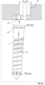
- the dowels 4,5 have a dowel body 27 which is shaped like a conventional dowel and is provided with a thread on both its outside and inside.
- the upper end section 28 of the dowel body 27 defines an insertion opening through which the respective sleeper screw 11,12 is screwed into the associated dowel 4,5.
- annular holding section 29 is formed which projects laterally from the dowel body 27 and is held on the dowel body 27 via four web-shaped connecting sections 30, 31, 32, 33 which are evenly distributed around the longitudinal axis L of the dowel body 27.
- a notch 34 extending in the circumferential direction U of the dowel body 27 is formed on each of the connecting sections 30 - 33.
- the material reduction thus produced forms a predetermined breaking point 35 at which the connecting sections 30 - 33 break when they are subjected to a tensile load that exceeds a limit value and is aligned coaxially to the longitudinal axis L.
- the holding section 29 is flattened to form guide surfaces 36, 37, which are flat and extend parallel to each other.
- a holder 38,39 for the respective associated dowel 4,5 is formed on the underside 20 of the base plate 3, in an area below the mouths 47 of the through openings 21,22.
- the holders 38, 39 each comprise a sliding guide 40, which is formed by two guide grooves 41, 42 that are parallel to one another, shaped like rails and extend parallel to the long sides of the base plate 3.
- the groove openings of the guide grooves 41, 42 face one another.
- the guide grooves 41, 42 are open at one end 43, 44 and are arranged at a distance corresponding to the guide surfaces 36, 37 of the holding section 29 of the respective dowel 4, 5.
- the respective dowel 4, 5 with its holding section 29 can be inserted into the sliding guide 40 from the open ends 43, 44 and moved therein until the longitudinal axis L of the dowel body 27 is aligned with the longitudinal axis of the respective through-opening 21, 22 ( Figures 6a - 6c).
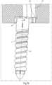
- a stop 45 is provided which determines the end position of the displacement of the dowel 4,5 in the sliding guide 40.
- a locking element in the form of a catch 46 formed on the base plate 3 is provided on the side of the sliding guide opposite the stop 45. This catch 46 has a contact surface bevelled towards the open ends 43,44 of the guide grooves 41,42.
- the dowel 4,5 slides accordingly with the top of its holding section 29 and the upper edge of its end section 28 over the catch 46 until the stop 45 is reached and the catch surface of the catch 46, which is aligned parallel to the longitudinal axis of the respective through opening 21,22, forms a stop which prevents the dowel 4,5 from moving back automatically in the associated sliding guide 40.
- the respective dowel 4.5 is in this way in the The associated holder 38,39 holds the base plate 3 in a positionally secure and twist-proof manner with respect to the respective associated through-opening 21,22 of the base plate 3.
- the smallest inner diameter Di_min of the through openings 21,22 is in each case so much larger than the largest outer diameter Dk_max of the dowel body 27 that the dowel body 27, when separated from the holding section 29, can be moved freely through the respectively associated through opening 21,22.
- the largest outer diameter DH_max of the holding section 29 is larger than the smallest inner diameter Di_min of the through openings 21, 22, so that the holding section 29 is supported with its upper contact surface on a shoulder 48 running around the mouth 47 of the respective through opening 21, 22 when a tensile load directed through the through opening 21, 22 in the direction of the upper side 14 of the base plate 3 acts on the respective dowel 4, 5.
- the dowel body 27 cast into the sleeper 2 of one of the dowels 4,5 is to be replaced because it is worn out through use, for example, the sleeper screw 11,12 screwed into the respective dowel body 27 is removed and a tool, also shaped like a screw and not shown here, is screwed into the dowel body 27 in its place.
- the tool is shaped in such a way that it does not press the dowel body 27 against the material of the sleeper 2 surrounding it, but rather allows loose rotation and a combined tensile load on the dowel body 27. The load thus exerted on the dowel body 27 is increased until the predetermined breaking points 35 of the connecting sections 30 - 33 break and the holding section 29 is separated from the dowel body 27.
- the dowel body 27 can then be moved, if necessary while maintaining the screwing movement, by means of the tool through the respective through hole 21, 22 to the upper side 14 of the base plate 3 until it is completely removed from the left behind dowel holder 49 of the sleeper 2 and can be freely pulled out of the through hole 21,22.
- the original holding section 29 of the dowel 4,5 remains in the respective holder 38,39.
- a new dowel is inserted through the respective through-opening 21, 22 into the dowel holder 49 of the sleeper 2.
- the new dowel has the shape of the previously removed dowel body 27 in the new state and has no holding section or the like, so that it can not only move freely through the through-opening 21, 22, but can also be screwed precisely into the dowel holder 49.
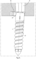
- Fig. 8 shown in a detail alternative embodiment of a rail fastening arrangement according to the invention of the Figures 1 - 7c illustrated embodiment of an arrangement 1 according to the invention for fastening the rail S.
- a recess in the form of a blind hole 50 is formed in the base plate 3 instead of the catch 46.
- a pin-shaped bolt 51 is inserted into this blind hole 50.
- the bolt 51 like the catch 46, prevents the dowel 4 from moving out of its desired position due to unintentional displacement in the guide grooves 41, 42 of the sliding guide 40.
- the advantage of the Fig. 8 The manner of locking by means of the bolt 51 shown in FIG. 1 is that the dowel 4, when it is moved in the sliding guide (according to Figure 7b ) does not have to overcome any locking projection, so that there is no risk of damage to the holding section 29 of the dowel 4.
- the invention thus provides a system and an arrangement 1 based thereon for fastening a rail S to a substrate 2.
- the system comprises a plate element 3 with a through opening 21, 22 leading from its upper side 14 to its lower side 20, a dowel 4, 5 which has a dowel body 27 which is embedded in the substrate 2 during use and an insertion opening delimited by an end section 28 of the dowel body 27 for inserting a fastening element 11, 12 into the dowel body 27.
- a holding section 29 which protrudes laterally from the end section 28 is connected to the end section 28 of the dowel body 27 via a connecting section 30 - 33 provided with a predetermined breaking point.
- the underside 20 of the plate element 3 is provided with a holder 38,39, into which the through opening 21,22 of the plate element 3 opens and in which the dowel 4,5 is held with its holding section 29.
- the holder 38,39 forms a stop 48 for the holding section 29, which acts in the longitudinal direction of the dowel 4,5.
- the inner contour of the through opening 21,22 of the plate element 3 is simultaneously adapted to the outer contour of the dowel body 27 such that the dowel body 27 can be moved through the through opening 21,22 of the plate element 3 after the connecting section 30 - 33 of the dowel 4,5 breaks.
Landscapes
- Engineering & Computer Science (AREA)
- Mechanical Engineering (AREA)
- Architecture (AREA)
- Civil Engineering (AREA)
- Structural Engineering (AREA)
- Connection Of Plates (AREA)
Claims (15)
- Système de fixation d'un rail (S) pour un véhicule ferroviaire sur un substrat (2), le système comportant- un élément plan (3) présentant une face inférieure (20) avec laquelle l'élément plan (3) est en appui sur le substrat (2) pendant l'utilisation, une face supérieure (14) opposée au substrat (2) pendant l'utilisation ainsi qu'une ouverture traversante (21, 22) menant de la face supérieure (14) à la face inférieure (20),
et- comprenant un ancrage (4, 5) présentant un corps d'ancrage (27) inséré dans le substrat (2) pendant l'utilisation et une ouverture d'introduction définie par une partie d'extrémité (28) du corps d'ancrage (27) pour insérer un élément de fixation (11, 12) dans le corps d'ancrage (27),- une partie de maintien (29) qui fait saillie latéralement de la partie d'extrémité (28) est connectée à la partie d'extrémité (28) du corps d'ancrage (27) via une partie de connexion (30 - 33),- un support (38, 39) étant prévu sur la face inférieure (20) de l'élément plan (3) dans lequel débouche l'ouverture traversante (21, 22) de l'élément plan (3),- et l'ancrage (4, 5) étant maintenu avec sa partie de maintien (29) dans le support (38, 39) qui forme une butée (48) pour la partie de maintien (29) de l'ancrage (4, 5) agissant dans la direction longitudinale de l'ancrage (4, 5), caractérisée en ce- que la partie de connexion (30 - 33) présente un point de rupture prédéterminé (35),
et- que le contour intérieur de l'ouverture de traversante (21, 22) de l'élément plan (3) est adapté au contour extérieur du corps d'ancrage (27) de sorte que le corps d'ancrage (27) peut être déplacé à travers l'ouverture de traversante (21, 22) de l'élément plan (3) après une rupture de la partie de connexion (30 - 33) de l'ancrage (4, 5). - Système selon la revendication 1, caractérisé en ce que le plus petit diamètre intérieur Di_min de l'ouverture traversante (21, 22) de l'élément plan (3) est supérieur au plus grand diamètre extérieur DaK_max du corps d'ancrage (27), mais inférieur au plus grand diamètre extérieur DaH_max de l'ancrage (4, 5) dans la zone dans laquelle la partie de maintien (29) est connectée au corps d'ancrage (27) (DaK_max < Di_min < DaH_max).
- Système selon l'une des revendications précédentes, caractérisé en ce que l'épaisseur ou la largeur de la partie de connexion (30 - 33) est réduite localement pour former son point de rupture prédéterminé (35).
- Système selon la revendication 3, caractérisé en ce qu'une encoche (34) ou une rainure est formée dans la partie de connexion (30 - 33) pour former le point de rupture prédéterminé (35).
- Système selon l'une quelconque des revendications précédentes, caractérisé en ce que la partie de connexion (30 - 33) est en forme de nervure ou de tenon.
- Système selon l'une quelconque des revendications précédentes, caractérisé en ce que la partie de maintien (29) est en forme d'un segment annulaire ou d'un anneau complet qui tourne autour de la partie d'extrémité (28) du corps d'ancrage (27) qui délimite l'ouverture d'insertion du corps d'ancrage (27).
- Système selon la revendication 6, caractérisé en ce que la partie de maintien (29) est connectée à la partie d'extrémité (28) du corps d'ancrage (27) par au moins deux parties de connexion (30 - 33), présentant respectivement un point de rupture prédéterminé (35), qui sont agencées espacées l'une de l'autre et réparties autour du corps d'ancrage (27) entre la partie d'extrémité (28) et la partie de maintien (29).
- Système selon l'une quelconque des revendications précédentes, caractérisé en ce que le support (38, 39) formé sur l'élément plan (3) pour l'ancrage (4, 5) comprend un guidage coulissant (40) dans lequel l'ancrage (4, 5) peut être inséré avec sa partie de maintien (29) et qui s'étend transversalement par rapport à l'axe longitudinal de l'ouverture traversante (21, 22) de l'élément plan (3) sur sa face inférieure (20).
- Système selon la revendication 8, caractérisé en ce que le support (38, 39) comprend un élément de butée (45) qui détermine la position de coulissement correcte de l'ancrage (4, 5) par rapport à l'ouverture traversante (21, 22) de l'élément plan (3).
- Système selon la revendication 8 ou 9, caractérisé en ce qu'un élément de verrouillage (46) est prévu pour fixer l'ancrage (4, 5) dans sa position correcte par rapport à l'ouverture traversante (21, 22) de l'élément plan (3).
- Système selon la revendication 9, caractérisé en ce que l'élément de verrouillage (46) est formé par un verrou moulé sur l'élément plan (3) ou un boulon (51) susceptible d'être fixé sur l'élément plan (3).
- Système selon l'une quelconque des revendications précédentes, caractérisé en ce que l'ancrage (4, 5) est maintenu sans possibilité de rotation par rapport à son axe longitudinal (L) dans le support (38, 39) de l'élément plan (3).
- Système selon l'une quelconque des revendications précédentes, caractérisé en ce que l'élément plan (3) est une plaque de calage sur la face supérieure de laquelle est formée une surface d'appui sur laquelle repose, pendant l'utilisation, le rail (S) à fixer.
- Agencement pour la fixation d'un rail (S) sur un substrat (2), l'agencement comprenant un système de fixation de rail formé par un élément plan (3) et un ancrage (4, 5) maintenu sur l'élément plan, l'ancrage (4, 5) étant moulé au moins avec une partie dans le substrat (2), caractérisé en ce que le système de fixation de rail est formé selon l'une des revendications précédentes.
- Procédé de réparation d'un agencement (1) conçu selon la revendication 14, comprenant les étapes de travail suivantes :- retrait d'un élément de fixation guidé à travers l'ouverture traversante (21, 22) de l'élément plan (3) et logé dans l'ancrage (4, 5) ;- introduction d'un outil à travers l'ouverture de traversante (21, 22) de l'élément plan (3) ;- sollicitation du corps d'ancrage (27) logé dans le composant formant le substrat (2) au moyen de l'outil, la charge agissant sur le corps d'ancrage (27) étant augmentée jusqu'à ce que la section de connexion (30 - 33) de l'ancrage (4, 5) se brise à son point de rupture prédéterminé ;- le déplacement du corps d'ancrage (27) hors du composant et à travers l'ouverture traversante (21, 22) de l'élément plan (3), le corps d'ancrage (27) laissant dans le composant un évidement d'ancrage formé par le corps d'ancrage (27) dans le composant;- introduction d'un nouveau corps d'ancrage (27) par l'ouverture traversante (21, 22) de l'élément plan (3) dans l'évidement d'ancrage du composant.
Applications Claiming Priority (2)
| Application Number | Priority Date | Filing Date | Title |
|---|---|---|---|
| DE102020132441.3A DE102020132441A1 (de) | 2020-12-07 | 2020-12-07 | System zur Befestigung, Anordnung zur Befestigung einer Schiene und Verfahren zur Reparatur einer solchen Anordnung |
| PCT/EP2021/084415 WO2022122661A1 (fr) | 2020-12-07 | 2021-12-06 | Système de fixation d'un rail et procédé de réparation |
Publications (2)
| Publication Number | Publication Date |
|---|---|
| EP4256209A1 EP4256209A1 (fr) | 2023-10-11 |
| EP4256209B1 true EP4256209B1 (fr) | 2024-10-30 |
Family
ID=79259353
Family Applications (1)
| Application Number | Title | Priority Date | Filing Date |
|---|---|---|---|
| EP21836363.8A Active EP4256209B1 (fr) | 2020-12-07 | 2021-12-06 | Système de fixation d'un rail et procédé de réparation |
Country Status (4)
| Country | Link |
|---|---|
| EP (1) | EP4256209B1 (fr) |
| CN (1) | CN116648539B (fr) |
| DE (1) | DE102020132441A1 (fr) |
| WO (1) | WO2022122661A1 (fr) |
Family Cites Families (9)
| Publication number | Priority date | Publication date | Assignee | Title |
|---|---|---|---|---|
| DE4413743A1 (de) * | 1994-04-20 | 1995-10-26 | Hilti Ag | Befestigungsanker |
| EP0763665A1 (fr) * | 1995-09-18 | 1997-03-19 | Stahl GmbH | Dispositif d'ancrage composite |
| DE102005003799A1 (de) | 2005-01-26 | 2006-08-03 | Bwg Gmbh & Co. Kg | Anordnung zum Befestigen einer Schiene sowie Führungsplatte |
| ES2283235B1 (es) | 2007-04-04 | 2009-03-01 | Mondragon Soluciones, S.L.U. | Vaina para sujeciones de railes ferroviarios, procedimiento para reemplazar dicha vaina en una traviesa y utiles para ejecutar dicho procedimiento. |
| DE202010015286U1 (de) * | 2010-08-24 | 2011-05-12 | Vossloh-Werke Gmbh | Unterlegplatte für ein Schienenbefestigungssystem und System zum Befestigen einer Schiene |
| FR2970717B1 (fr) * | 2011-01-20 | 2014-06-27 | Vape Rail Int | Dispositif d'ancrage servant a la fixation d'un rail de voie de chemin de fer a une traverse |
| DE202015103972U1 (de) | 2015-07-16 | 2016-10-19 | WOCO IPS GmbH | Montageplatte mit Rasthaken |
| DE102018100554A1 (de) | 2018-01-11 | 2019-07-11 | Schwihag Ag | Schienenbefestigungssystem |
| DE102018117453A1 (de) | 2018-07-19 | 2020-01-23 | Schwihag Ag Gleis- Und Weichentechnik | Schienenbefestigungssystem |
-
2020
- 2020-12-07 DE DE102020132441.3A patent/DE102020132441A1/de not_active Ceased
-
2021
- 2021-12-06 WO PCT/EP2021/084415 patent/WO2022122661A1/fr not_active Ceased
- 2021-12-06 EP EP21836363.8A patent/EP4256209B1/fr active Active
- 2021-12-06 CN CN202180082462.0A patent/CN116648539B/zh active Active
Also Published As
| Publication number | Publication date |
|---|---|
| CN116648539A (zh) | 2023-08-25 |
| WO2022122661A1 (fr) | 2022-06-16 |
| DE102020132441A1 (de) | 2022-06-09 |
| CN116648539B (zh) | 2026-02-27 |
| EP4256209A1 (fr) | 2023-10-11 |
Similar Documents
| Publication | Publication Date | Title |
|---|---|---|
| DE202009014434U1 (de) | Unterlegplatte für die Befestigung einer Schiene auf einem festen Untergrund und Befestigung einer Schiene | |
| EP2163347A2 (fr) | Dispositif variable adaptable destiné à retirer des injecteurs | |
| EP1197319B1 (fr) | Entraînement par coin | |
| EP1647782A2 (fr) | Dispositif de support d'au moins un collecteur solaire | |
| EP0904463B1 (fr) | Dispositif pour fixer la position de corps moules d'un passage a niveau sur des voies ferrees | |
| DE3629030A1 (de) | Vorrichtung zur fixierung roehrenfoermiger einbauteile | |
| DE2402054C2 (de) | Vorrichtung zum Festspannen von Werkstücken auf einer Aufspannplatte | |
| EP4256209B1 (fr) | Système de fixation d'un rail et procédé de réparation | |
| DE102013209111B4 (de) | Einspannvorrichtung, insbesondere zur Aufnahme und zum Einspannen eines Bauteils, sowie Einspannsystem mit einer solchen Einspannvorrichtung | |
| DE19821255A1 (de) | Befestigungsvorrichtung | |
| EP4245457A1 (fr) | Dispositif de levage et de transport | |
| DE69305423T2 (de) | Verkehrszeichen | |
| DE102009014566B4 (de) | Werkzeuge zur Herstellung von formstabilen Produkten aus Sand | |
| DE10007454C2 (de) | Toleranzausgleich-Element | |
| DE29824254U1 (de) | Befestigungsvorrichtung | |
| DE9421582U1 (de) | Lösbare Arretierung einer auf einem Grundkörper aufliegenden Abdeckung | |
| DE102023119208B3 (de) | Hebe- und Transportvorrichtung | |
| DE102006000816B3 (de) | Führungsschiene für den Umlenkbeschlag eines Sicherheitsgurtes für Kraftfahrzeuge | |
| EP4440762B1 (fr) | Système d'étanchéité pour installation de coulée continue | |
| EP2803533B1 (fr) | Dispositif destiné à agencer une barre présentant un canal longitudinal sur un support | |
| DE102004028307B4 (de) | Halteranordnung, insbesondere zur Halterung von Zusatzaggregaten, wie Heizgerät, an einem Fahrzeug | |
| DE202013002950U1 (de) | Vorrichtung zur unterseitigen Abstützung eines Kfz-Motors | |
| DE102018203080A1 (de) | Fundamentsystem für die lagerung von flächig nebeneinander angeordneten solarpaneelen | |
| DE102022108167A1 (de) | Spreizniet | |
| DE4236159A1 (de) | Platzhalter für Schienenbefestigung |
Legal Events
| Date | Code | Title | Description |
|---|---|---|---|
| STAA | Information on the status of an ep patent application or granted ep patent |
Free format text: STATUS: UNKNOWN |
|
| STAA | Information on the status of an ep patent application or granted ep patent |
Free format text: STATUS: THE INTERNATIONAL PUBLICATION HAS BEEN MADE |
|
| PUAI | Public reference made under article 153(3) epc to a published international application that has entered the european phase |
Free format text: ORIGINAL CODE: 0009012 |
|
| STAA | Information on the status of an ep patent application or granted ep patent |
Free format text: STATUS: REQUEST FOR EXAMINATION WAS MADE |
|
| 17P | Request for examination filed |
Effective date: 20230523 |
|
| AK | Designated contracting states |
Kind code of ref document: A1 Designated state(s): AL AT BE BG CH CY CZ DE DK EE ES FI FR GB GR HR HU IE IS IT LI LT LU LV MC MK MT NL NO PL PT RO RS SE SI SK SM TR |
|
| DAV | Request for validation of the european patent (deleted) | ||
| DAX | Request for extension of the european patent (deleted) | ||
| GRAP | Despatch of communication of intention to grant a patent |
Free format text: ORIGINAL CODE: EPIDOSNIGR1 |
|
| STAA | Information on the status of an ep patent application or granted ep patent |
Free format text: STATUS: GRANT OF PATENT IS INTENDED |
|
| INTG | Intention to grant announced |
Effective date: 20240523 |
|
| GRAS | Grant fee paid |
Free format text: ORIGINAL CODE: EPIDOSNIGR3 |
|
| GRAA | (expected) grant |
Free format text: ORIGINAL CODE: 0009210 |
|
| STAA | Information on the status of an ep patent application or granted ep patent |
Free format text: STATUS: THE PATENT HAS BEEN GRANTED |
|
| AK | Designated contracting states |
Kind code of ref document: B1 Designated state(s): AL AT BE BG CH CY CZ DE DK EE ES FI FR GB GR HR HU IE IS IT LI LT LU LV MC MK MT NL NO PL PT RO RS SE SI SK SM TR |
|
| REG | Reference to a national code |
Ref country code: GB Ref legal event code: FG4D Free format text: NOT ENGLISH |
|
| REG | Reference to a national code |
Ref country code: CH Ref legal event code: EP |
|
| REG | Reference to a national code |
Ref country code: IE Ref legal event code: FG4D Free format text: LANGUAGE OF EP DOCUMENT: GERMAN |
|
| REG | Reference to a national code |
Ref country code: DE Ref legal event code: R096 Ref document number: 502021005666 Country of ref document: DE |
|
| P01 | Opt-out of the competence of the unified patent court (upc) registered |
Free format text: CASE NUMBER: APP_56994/2024 Effective date: 20241018 |
|
| REG | Reference to a national code |
Ref country code: LT Ref legal event code: MG9D |
|
| REG | Reference to a national code |
Ref country code: NL Ref legal event code: MP Effective date: 20241030 |
|
| PG25 | Lapsed in a contracting state [announced via postgrant information from national office to epo] |
Ref country code: PT Free format text: LAPSE BECAUSE OF FAILURE TO SUBMIT A TRANSLATION OF THE DESCRIPTION OR TO PAY THE FEE WITHIN THE PRESCRIBED TIME-LIMIT Effective date: 20250228 Ref country code: HR Free format text: LAPSE BECAUSE OF FAILURE TO SUBMIT A TRANSLATION OF THE DESCRIPTION OR TO PAY THE FEE WITHIN THE PRESCRIBED TIME-LIMIT Effective date: 20241030 Ref country code: IS Free format text: LAPSE BECAUSE OF FAILURE TO SUBMIT A TRANSLATION OF THE DESCRIPTION OR TO PAY THE FEE WITHIN THE PRESCRIBED TIME-LIMIT Effective date: 20250228 |
|
| PG25 | Lapsed in a contracting state [announced via postgrant information from national office to epo] |
Ref country code: NL Free format text: LAPSE BECAUSE OF FAILURE TO SUBMIT A TRANSLATION OF THE DESCRIPTION OR TO PAY THE FEE WITHIN THE PRESCRIBED TIME-LIMIT Effective date: 20241030 Ref country code: FI Free format text: LAPSE BECAUSE OF FAILURE TO SUBMIT A TRANSLATION OF THE DESCRIPTION OR TO PAY THE FEE WITHIN THE PRESCRIBED TIME-LIMIT Effective date: 20241030 |
|
| PG25 | Lapsed in a contracting state [announced via postgrant information from national office to epo] |
Ref country code: BG Free format text: LAPSE BECAUSE OF FAILURE TO SUBMIT A TRANSLATION OF THE DESCRIPTION OR TO PAY THE FEE WITHIN THE PRESCRIBED TIME-LIMIT Effective date: 20241030 |
|
| PG25 | Lapsed in a contracting state [announced via postgrant information from national office to epo] |
Ref country code: ES Free format text: LAPSE BECAUSE OF FAILURE TO SUBMIT A TRANSLATION OF THE DESCRIPTION OR TO PAY THE FEE WITHIN THE PRESCRIBED TIME-LIMIT Effective date: 20241030 |
|
| PG25 | Lapsed in a contracting state [announced via postgrant information from national office to epo] |
Ref country code: NO Free format text: LAPSE BECAUSE OF FAILURE TO SUBMIT A TRANSLATION OF THE DESCRIPTION OR TO PAY THE FEE WITHIN THE PRESCRIBED TIME-LIMIT Effective date: 20250130 |
|
| PG25 | Lapsed in a contracting state [announced via postgrant information from national office to epo] |
Ref country code: LV Free format text: LAPSE BECAUSE OF FAILURE TO SUBMIT A TRANSLATION OF THE DESCRIPTION OR TO PAY THE FEE WITHIN THE PRESCRIBED TIME-LIMIT Effective date: 20241030 Ref country code: GR Free format text: LAPSE BECAUSE OF FAILURE TO SUBMIT A TRANSLATION OF THE DESCRIPTION OR TO PAY THE FEE WITHIN THE PRESCRIBED TIME-LIMIT Effective date: 20250131 |
|
| PG25 | Lapsed in a contracting state [announced via postgrant information from national office to epo] |
Ref country code: PL Free format text: LAPSE BECAUSE OF FAILURE TO SUBMIT A TRANSLATION OF THE DESCRIPTION OR TO PAY THE FEE WITHIN THE PRESCRIBED TIME-LIMIT Effective date: 20241030 |
|
| PG25 | Lapsed in a contracting state [announced via postgrant information from national office to epo] |
Ref country code: RS Free format text: LAPSE BECAUSE OF FAILURE TO SUBMIT A TRANSLATION OF THE DESCRIPTION OR TO PAY THE FEE WITHIN THE PRESCRIBED TIME-LIMIT Effective date: 20250130 |
|
| PG25 | Lapsed in a contracting state [announced via postgrant information from national office to epo] |
Ref country code: SM Free format text: LAPSE BECAUSE OF FAILURE TO SUBMIT A TRANSLATION OF THE DESCRIPTION OR TO PAY THE FEE WITHIN THE PRESCRIBED TIME-LIMIT Effective date: 20241030 |
|
| PG25 | Lapsed in a contracting state [announced via postgrant information from national office to epo] |
Ref country code: MC Free format text: LAPSE BECAUSE OF FAILURE TO SUBMIT A TRANSLATION OF THE DESCRIPTION OR TO PAY THE FEE WITHIN THE PRESCRIBED TIME-LIMIT Effective date: 20241030 |
|
| PG25 | Lapsed in a contracting state [announced via postgrant information from national office to epo] |
Ref country code: DK Free format text: LAPSE BECAUSE OF FAILURE TO SUBMIT A TRANSLATION OF THE DESCRIPTION OR TO PAY THE FEE WITHIN THE PRESCRIBED TIME-LIMIT Effective date: 20241030 |
|
| PG25 | Lapsed in a contracting state [announced via postgrant information from national office to epo] |
Ref country code: EE Free format text: LAPSE BECAUSE OF FAILURE TO SUBMIT A TRANSLATION OF THE DESCRIPTION OR TO PAY THE FEE WITHIN THE PRESCRIBED TIME-LIMIT Effective date: 20241030 |
|
| PG25 | Lapsed in a contracting state [announced via postgrant information from national office to epo] |
Ref country code: RO Free format text: LAPSE BECAUSE OF FAILURE TO SUBMIT A TRANSLATION OF THE DESCRIPTION OR TO PAY THE FEE WITHIN THE PRESCRIBED TIME-LIMIT Effective date: 20241030 |
|
| PG25 | Lapsed in a contracting state [announced via postgrant information from national office to epo] |
Ref country code: SK Free format text: LAPSE BECAUSE OF FAILURE TO SUBMIT A TRANSLATION OF THE DESCRIPTION OR TO PAY THE FEE WITHIN THE PRESCRIBED TIME-LIMIT Effective date: 20241030 |
|
| PG25 | Lapsed in a contracting state [announced via postgrant information from national office to epo] |
Ref country code: CZ Free format text: LAPSE BECAUSE OF FAILURE TO SUBMIT A TRANSLATION OF THE DESCRIPTION OR TO PAY THE FEE WITHIN THE PRESCRIBED TIME-LIMIT Effective date: 20241030 |
|
| PG25 | Lapsed in a contracting state [announced via postgrant information from national office to epo] |
Ref country code: IT Free format text: LAPSE BECAUSE OF FAILURE TO SUBMIT A TRANSLATION OF THE DESCRIPTION OR TO PAY THE FEE WITHIN THE PRESCRIBED TIME-LIMIT Effective date: 20241030 |
|
| REG | Reference to a national code |
Ref country code: DE Ref legal event code: R097 Ref document number: 502021005666 Country of ref document: DE |
|
| PG25 | Lapsed in a contracting state [announced via postgrant information from national office to epo] |
Ref country code: LU Free format text: LAPSE BECAUSE OF NON-PAYMENT OF DUE FEES Effective date: 20241206 |
|
| PLBE | No opposition filed within time limit |
Free format text: ORIGINAL CODE: 0009261 |
|
| STAA | Information on the status of an ep patent application or granted ep patent |
Free format text: STATUS: NO OPPOSITION FILED WITHIN TIME LIMIT |
|
| PG25 | Lapsed in a contracting state [announced via postgrant information from national office to epo] |
Ref country code: SE Free format text: LAPSE BECAUSE OF FAILURE TO SUBMIT A TRANSLATION OF THE DESCRIPTION OR TO PAY THE FEE WITHIN THE PRESCRIBED TIME-LIMIT Effective date: 20241030 |
|
| 26N | No opposition filed |
Effective date: 20250731 |
|
| REG | Reference to a national code |
Ref country code: BE Ref legal event code: MM Effective date: 20241231 |
|
| PG25 | Lapsed in a contracting state [announced via postgrant information from national office to epo] |
Ref country code: BE Free format text: LAPSE BECAUSE OF NON-PAYMENT OF DUE FEES Effective date: 20241231 |
|
| PG25 | Lapsed in a contracting state [announced via postgrant information from national office to epo] |
Ref country code: IE Free format text: LAPSE BECAUSE OF NON-PAYMENT OF DUE FEES Effective date: 20241206 |
|
| REG | Reference to a national code |
Ref country code: CH Ref legal event code: U11 Free format text: ST27 STATUS EVENT CODE: U-0-0-U10-U11 (AS PROVIDED BY THE NATIONAL OFFICE) Effective date: 20260101 |
|
| PGFP | Annual fee paid to national office [announced via postgrant information from national office to epo] |
Ref country code: DE Payment date: 20251217 Year of fee payment: 5 |
|
| PGFP | Annual fee paid to national office [announced via postgrant information from national office to epo] |
Ref country code: GB Payment date: 20251218 Year of fee payment: 5 |
|
| PGFP | Annual fee paid to national office [announced via postgrant information from national office to epo] |
Ref country code: AT Payment date: 20260113 Year of fee payment: 5 |
|
| PGFP | Annual fee paid to national office [announced via postgrant information from national office to epo] |
Ref country code: FR Payment date: 20251217 Year of fee payment: 5 |
|
| PGFP | Annual fee paid to national office [announced via postgrant information from national office to epo] |
Ref country code: TR Payment date: 20251125 Year of fee payment: 5 |
|
| PGFP | Annual fee paid to national office [announced via postgrant information from national office to epo] |
Ref country code: CH Payment date: 20260101 Year of fee payment: 5 |