EP2166546A2 - Reaktoreinheit mit einem elektrischem Anschluss - Google Patents
Reaktoreinheit mit einem elektrischem Anschluss Download PDFInfo
- Publication number
- EP2166546A2 EP2166546A2 EP09167731A EP09167731A EP2166546A2 EP 2166546 A2 EP2166546 A2 EP 2166546A2 EP 09167731 A EP09167731 A EP 09167731A EP 09167731 A EP09167731 A EP 09167731A EP 2166546 A2 EP2166546 A2 EP 2166546A2
- Authority
- EP
- European Patent Office
- Prior art keywords
- pressing
- connecting part
- reactor unit
- electric terminal
- copper
- Prior art date
- Legal status (The legal status is an assumption and is not a legal conclusion. Google has not performed a legal analysis and makes no representation as to the accuracy of the status listed.)
- Granted
Links
- 238000003825 pressing Methods 0.000 claims abstract description 50
- 229910052782 aluminium Inorganic materials 0.000 claims abstract description 30
- XAGFODPZIPBFFR-UHFFFAOYSA-N aluminium Chemical compound [Al] XAGFODPZIPBFFR-UHFFFAOYSA-N 0.000 claims abstract description 30
- 238000004804 winding Methods 0.000 claims abstract description 29
- 238000003466 welding Methods 0.000 claims abstract description 13
- XEEYBQQBJWHFJM-UHFFFAOYSA-N Iron Chemical group [Fe] XEEYBQQBJWHFJM-UHFFFAOYSA-N 0.000 claims abstract description 11
- 229920002050 silicone resin Polymers 0.000 claims description 3
- 239000000463 material Substances 0.000 abstract description 8
- RYGMFSIKBFXOCR-UHFFFAOYSA-N Copper Chemical compound [Cu] RYGMFSIKBFXOCR-UHFFFAOYSA-N 0.000 description 16
- 239000010949 copper Substances 0.000 description 14
- 229910052802 copper Inorganic materials 0.000 description 14
- AZDRQVAHHNSJOQ-UHFFFAOYSA-N alumane Chemical group [AlH3] AZDRQVAHHNSJOQ-UHFFFAOYSA-N 0.000 description 7
- 210000003298 dental enamel Anatomy 0.000 description 4
- 238000009413 insulation Methods 0.000 description 4
- 229910000679 solder Inorganic materials 0.000 description 4
- 230000007613 environmental effect Effects 0.000 description 3
- WABPQHHGFIMREM-UHFFFAOYSA-N lead(0) Chemical compound [Pb] WABPQHHGFIMREM-UHFFFAOYSA-N 0.000 description 3
- 229910052751 metal Inorganic materials 0.000 description 3
- 239000002184 metal Substances 0.000 description 3
- 150000002739 metals Chemical class 0.000 description 3
- 239000002966 varnish Substances 0.000 description 3
- 229910000831 Steel Inorganic materials 0.000 description 2
- 239000011248 coating agent Substances 0.000 description 2
- 238000000576 coating method Methods 0.000 description 2
- 230000007797 corrosion Effects 0.000 description 2
- 238000005260 corrosion Methods 0.000 description 2
- 229910052742 iron Inorganic materials 0.000 description 2
- NJPPVKZQTLUDBO-UHFFFAOYSA-N novaluron Chemical compound C1=C(Cl)C(OC(F)(F)C(OC(F)(F)F)F)=CC=C1NC(=O)NC(=O)C1=C(F)C=CC=C1F NJPPVKZQTLUDBO-UHFFFAOYSA-N 0.000 description 2
- 239000010959 steel Substances 0.000 description 2
- 230000001629 suppression Effects 0.000 description 2
- 238000005406 washing Methods 0.000 description 2
- 230000003679 aging effect Effects 0.000 description 1
- 230000002950 deficient Effects 0.000 description 1
- 230000000694 effects Effects 0.000 description 1
- 230000020169 heat generation Effects 0.000 description 1
- 238000005470 impregnation Methods 0.000 description 1
- JEIPFZHSYJVQDO-UHFFFAOYSA-N iron(III) oxide Inorganic materials O=[Fe]O[Fe]=O JEIPFZHSYJVQDO-UHFFFAOYSA-N 0.000 description 1
- 238000005304 joining Methods 0.000 description 1
- 238000004519 manufacturing process Methods 0.000 description 1
- 238000000034 method Methods 0.000 description 1
- 230000002265 prevention Effects 0.000 description 1
- 230000035882 stress Effects 0.000 description 1
- 230000008646 thermal stress Effects 0.000 description 1
- XLYOFNOQVPJJNP-UHFFFAOYSA-N water Substances O XLYOFNOQVPJJNP-UHFFFAOYSA-N 0.000 description 1
Images


Classifications
-
- H—ELECTRICITY
- H01—ELECTRIC ELEMENTS
- H01F—MAGNETS; INDUCTANCES; TRANSFORMERS; SELECTION OF MATERIALS FOR THEIR MAGNETIC PROPERTIES
- H01F27/00—Details of transformers or inductances, in general
- H01F27/28—Coils; Windings; Conductive connections
- H01F27/2823—Wires
- H01F27/2828—Construction of conductive connections, of leads
-
- H—ELECTRICITY
- H01—ELECTRIC ELEMENTS
- H01F—MAGNETS; INDUCTANCES; TRANSFORMERS; SELECTION OF MATERIALS FOR THEIR MAGNETIC PROPERTIES
- H01F37/00—Fixed inductances not covered by group H01F17/00
-
- H—ELECTRICITY
- H01—ELECTRIC ELEMENTS
- H01R—ELECTRICALLY-CONDUCTIVE CONNECTIONS; STRUCTURAL ASSOCIATIONS OF A PLURALITY OF MUTUALLY-INSULATED ELECTRICAL CONNECTING ELEMENTS; COUPLING DEVICES; CURRENT COLLECTORS
- H01R11/00—Individual connecting elements providing two or more spaced connecting locations for conductive members which are, or may be, thereby interconnected, e.g. end pieces for wires or cables supported by the wire or cable and having means for facilitating electrical connection to some other wire, terminal, or conductive member, blocks of binding posts
- H01R11/11—End pieces or tapping pieces for wires, supported by the wire and for facilitating electrical connection to some other wire, terminal or conductive member
- H01R11/16—End pieces terminating in a soldering tip or socket
-
- H—ELECTRICITY
- H01—ELECTRIC ELEMENTS
- H01R—ELECTRICALLY-CONDUCTIVE CONNECTIONS; STRUCTURAL ASSOCIATIONS OF A PLURALITY OF MUTUALLY-INSULATED ELECTRICAL CONNECTING ELEMENTS; COUPLING DEVICES; CURRENT COLLECTORS
- H01R4/00—Electrically-conductive connections between two or more conductive members in direct contact, i.e. touching one another; Means for effecting or maintaining such contact; Electrically-conductive connections having two or more spaced connecting locations for conductors and using contact members penetrating insulation
- H01R4/02—Soldered or welded connections
- H01R4/023—Soldered or welded connections between cables or wires and terminals
-
- H—ELECTRICITY
- H01—ELECTRIC ELEMENTS
- H01R—ELECTRICALLY-CONDUCTIVE CONNECTIONS; STRUCTURAL ASSOCIATIONS OF A PLURALITY OF MUTUALLY-INSULATED ELECTRICAL CONNECTING ELEMENTS; COUPLING DEVICES; CURRENT COLLECTORS
- H01R4/00—Electrically-conductive connections between two or more conductive members in direct contact, i.e. touching one another; Means for effecting or maintaining such contact; Electrically-conductive connections having two or more spaced connecting locations for conductors and using contact members penetrating insulation
- H01R4/02—Soldered or welded connections
- H01R4/029—Welded connections
-
- H—ELECTRICITY
- H01—ELECTRIC ELEMENTS
- H01R—ELECTRICALLY-CONDUCTIVE CONNECTIONS; STRUCTURAL ASSOCIATIONS OF A PLURALITY OF MUTUALLY-INSULATED ELECTRICAL CONNECTING ELEMENTS; COUPLING DEVICES; CURRENT COLLECTORS
- H01R4/00—Electrically-conductive connections between two or more conductive members in direct contact, i.e. touching one another; Means for effecting or maintaining such contact; Electrically-conductive connections having two or more spaced connecting locations for conductors and using contact members penetrating insulation
- H01R4/10—Electrically-conductive connections between two or more conductive members in direct contact, i.e. touching one another; Means for effecting or maintaining such contact; Electrically-conductive connections having two or more spaced connecting locations for conductors and using contact members penetrating insulation effected solely by twisting, wrapping, bending, crimping, or other permanent deformation
- H01R4/18—Electrically-conductive connections between two or more conductive members in direct contact, i.e. touching one another; Means for effecting or maintaining such contact; Electrically-conductive connections having two or more spaced connecting locations for conductors and using contact members penetrating insulation effected solely by twisting, wrapping, bending, crimping, or other permanent deformation by crimping
- H01R4/183—Electrically-conductive connections between two or more conductive members in direct contact, i.e. touching one another; Means for effecting or maintaining such contact; Electrically-conductive connections having two or more spaced connecting locations for conductors and using contact members penetrating insulation effected solely by twisting, wrapping, bending, crimping, or other permanent deformation by crimping for cylindrical elongated bodies, e.g. cables having circular cross-section
- H01R4/184—Electrically-conductive connections between two or more conductive members in direct contact, i.e. touching one another; Means for effecting or maintaining such contact; Electrically-conductive connections having two or more spaced connecting locations for conductors and using contact members penetrating insulation effected solely by twisting, wrapping, bending, crimping, or other permanent deformation by crimping for cylindrical elongated bodies, e.g. cables having circular cross-section comprising a U-shaped wire-receiving portion
-
- H—ELECTRICITY
- H01—ELECTRIC ELEMENTS
- H01R—ELECTRICALLY-CONDUCTIVE CONNECTIONS; STRUCTURAL ASSOCIATIONS OF A PLURALITY OF MUTUALLY-INSULATED ELECTRICAL CONNECTING ELEMENTS; COUPLING DEVICES; CURRENT COLLECTORS
- H01R4/00—Electrically-conductive connections between two or more conductive members in direct contact, i.e. touching one another; Means for effecting or maintaining such contact; Electrically-conductive connections having two or more spaced connecting locations for conductors and using contact members penetrating insulation
- H01R4/58—Electrically-conductive connections between two or more conductive members in direct contact, i.e. touching one another; Means for effecting or maintaining such contact; Electrically-conductive connections having two or more spaced connecting locations for conductors and using contact members penetrating insulation characterised by the form or material of the contacting members
- H01R4/62—Connections between conductors of different materials; Connections between or with aluminium or steel-core aluminium conductors
-
- H—ELECTRICITY
- H01—ELECTRIC ELEMENTS
- H01R—ELECTRICALLY-CONDUCTIVE CONNECTIONS; STRUCTURAL ASSOCIATIONS OF A PLURALITY OF MUTUALLY-INSULATED ELECTRICAL CONNECTING ELEMENTS; COUPLING DEVICES; CURRENT COLLECTORS
- H01R4/00—Electrically-conductive connections between two or more conductive members in direct contact, i.e. touching one another; Means for effecting or maintaining such contact; Electrically-conductive connections having two or more spaced connecting locations for conductors and using contact members penetrating insulation
- H01R4/70—Insulation of connections
- H01R4/72—Insulation of connections using a heat shrinking insulating sleeve
-
- H—ELECTRICITY
- H01—ELECTRIC ELEMENTS
- H01F—MAGNETS; INDUCTANCES; TRANSFORMERS; SELECTION OF MATERIALS FOR THEIR MAGNETIC PROPERTIES
- H01F27/00—Details of transformers or inductances, in general
- H01F27/28—Coils; Windings; Conductive connections
- H01F27/29—Terminals; Tapping arrangements for signal inductances
-
- H—ELECTRICITY
- H01—ELECTRIC ELEMENTS
- H01R—ELECTRICALLY-CONDUCTIVE CONNECTIONS; STRUCTURAL ASSOCIATIONS OF A PLURALITY OF MUTUALLY-INSULATED ELECTRICAL CONNECTING ELEMENTS; COUPLING DEVICES; CURRENT COLLECTORS
- H01R4/00—Electrically-conductive connections between two or more conductive members in direct contact, i.e. touching one another; Means for effecting or maintaining such contact; Electrically-conductive connections having two or more spaced connecting locations for conductors and using contact members penetrating insulation
- H01R4/10—Electrically-conductive connections between two or more conductive members in direct contact, i.e. touching one another; Means for effecting or maintaining such contact; Electrically-conductive connections having two or more spaced connecting locations for conductors and using contact members penetrating insulation effected solely by twisting, wrapping, bending, crimping, or other permanent deformation
- H01R4/18—Electrically-conductive connections between two or more conductive members in direct contact, i.e. touching one another; Means for effecting or maintaining such contact; Electrically-conductive connections having two or more spaced connecting locations for conductors and using contact members penetrating insulation effected solely by twisting, wrapping, bending, crimping, or other permanent deformation by crimping
- H01R4/187—Electrically-conductive connections between two or more conductive members in direct contact, i.e. touching one another; Means for effecting or maintaining such contact; Electrically-conductive connections having two or more spaced connecting locations for conductors and using contact members penetrating insulation effected solely by twisting, wrapping, bending, crimping, or other permanent deformation by crimping combined with soldering or welding
Definitions
- the present invention relates to a reactor unit having electrical connecting means between winding coils and copper wires using aluminum wires such as a reactor used in electric and electronic appliances.
- FIG. 5 is a front view of a conventional reactor having electrical connecting means between winding coils and copper wires.
- iron core 2 made of iron is mounted on pedestal 1 made of iron.
- Winding coil 4 wound with aluminum wires 3 having an enamel film baked on the surface is inserted in iron core 2. Then, the entire reactor is impregnated in varnish.
- the material of winding coil 4 is composed of aluminum wires 3.
- Aluminum wires 3 are less expensive than copper wires, and are used widely in reactors and other windings recently.
- the enamel parts are removed from the beginning and end of winding of winding coil 4 of aluminum wires 3, and aluminum core 5 is soldered and connected to other electric terminal 6 made of copper by means of solder 7.
- a power supply input into reactor 8 from outside is supplied by inserting a tab terminal or the like connected to a lead wire or the like into electric terminal 6.
- the present invention is intended to solve the problems of the conventional means, and it is hence an object thereof to present a reactor unit having electrical connecting part between winding coils of aluminum wires and copper wires, and more specifically an inexpensive and highly reliable reactor unit capable of preventing faulty contact in spite of sudden changes in the environmental temperature of the connection part.
- the reactor unit of the present invention includes a winding coil having aluminum wires wound around an iron core, and a copper-made electric terminal connected to end parts of the winding coil, in which the electric terminal has a pressing and connecting part for pressing and connecting aluminum wires of the winding coil at one end, and a welding part of a nearly flat shape at other end.
- This configuration realizes an inexpensive and highly reliable reactor unit having electrical connecting means between winding coils and copper wires not causing faulty contact in spite of sudden changes in the environmental temperature.
- FIG. 1 to FIG. 4 This preferred embodiment is explained in FIG. 1 to FIG. 4 , relating to a reactor unit having electrical connecting part between winding coils using aluminum wires and copper wires for power supply input for the purpose of suppression of harmonic currents from washing machine or the like of inverter control, or improvement of power factor. It must be noted, however, that the present invention is not limited to the illustrated preferred embodiment alone.
- FIG. 1 is a sectional view of reactor unit in preferred embodiment 1 of the present invention.
- thin electromagnetic steel plates blanked in a shape of letter E by a pressing die are laminated and welded to obtain E-core 9, to which winding coils 10 wound with aluminum wires having an enamel film baked on the surface are fitted from the upper part.
- Thin electromagnetic steel plates blanked in a shape of letter I by a pressing die are laminated and welded to obtain I-core 11, which is mounted on E-core 9, and the contact side surface of outer circumference is welded and fixed by means of welding member 12.
- E-core 9 is welded and fixed to iron-made pedestal 13 by means of welding member 12 so as to be tightened with screws to washing machine or other machine to be applied.
- Insulation tape 15 for insulation is wound on the outer circumference of winding coils 10.
- the entire reactor is impregnated in varnish after completion of all processes of welding and fixing.
- the purpose of impregnation in varnish is rust prevention of iron cores of E-core 9 and I-core 11, suppression of magnetic distortion sound, and protection of coil insulation tape from moisture, among others.
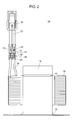
- FIG. 2 is a front view of the reactor unit. As shown in FIG. 2 , winding coils 10 wound with aluminum wires 18 are fitted to iron core 16 formed of E-core 9 and I-core 11. Enamel parts are removed from start and end of winding of winding coils 10 of aluminum wires 18, and aluminum core wires 19 of aluminum wires 18 are exposed by about 10 mm, and pressed, connected and fixed to pressing and connecting part 25 of copper-made electric terminal 17, thereby composing reactor unit 14.
- the core wire of copper-made lead wire 21 with connector 22 for supplying power source to the reactor is welded and fixed to welding part 17c of a nearly flat shape of electric terminal 17 by spot welding.
- junction part 20 between aluminum core wire 19 and copper-made electric terminal 17 produces a potential difference because dissimilar metals of aluminum and copper are connected. Therefore if water or moisture sticks, an electrolytic corrosion occurs, and the contact resistance may be increased. Therefore, by applying silicone resin 23 to cover at least the entire area of the connection part of dissimilar metals by using a brush or the like, an electric connection can be assured appropriately.
- junction part 20 by coating the outer circumference of junction part 20 with heat shrink tube 24 which shrinks when exposed to high temperature, as insulation tape, the waterproof effect may be further heightened.
- FIG. 3 shows the detail of the connection part.
- FIG. 3A is a side magnified view of the connection part.
- FIG. 3B is a front magnified view of the connection part.
- FIG. 3C is a sectional view of part 3C-3C of FIG. 3A.
- FIG. 3D is a sectional view of part 3D-3D of FIG. 3A .
- section 3C-3C shows first pressing and connecting part 17a of low pressing height, and the pressing crimp height (pressing and connecting height) is ⁇ A
- section 3D-3D shows second pressing and connecting part 17b of high pressing height
- the pressing crimp height is ⁇ B. Therefore, terminal end part 30 is processed by changing the pressing height so that the crimp height relation may be ⁇ A ⁇ ⁇ B.
- terminal end part 30 In first pressing and connecting part 17a of section 3C-3C, terminal end part 30 is bent and processed to such an extent that inside aluminum core wire 19 may be compressed and deformed.
- second pressing and connecting part 17b of section 3D-3D terminal end part 30 is bent and processed to such an extent that inside aluminum core wire 19 may not be deformed plastically.
- an aluminum wire is soft in surface hardness, and the aluminum itself is elongated by stress of pressing and connecting, and is deformed plastically. It is hence difficult to satisfy both the stability of contact resistance required in pressing and fixing and the assurance of tensile strength.
- the pressing and connecting height is divided, and the contact resistance is stabilized in first pressing and connecting part 17a of section 3C-3C, and the tensile strength is assured in second pressing and connecting part 17b of section 3D-3D, and the required roles for connection are divided, and successive pressing and connecting may be achieved.
- the opposite side of aluminum wire 18 of electric terminal 17 is welding part 17c for joining copper-made lead wire 21 and electric terminal 17 by spot welding.
- This welding part 17c is welding between copper materials, and is free from difference in coefficient of thermal expansion, junction part 20 has a strong resistance to temperature changes.
- FIG. 4 shows an electric characteristic graph of the reactor unit of the preferred embodiment.
- the axis of abscissas denotes the pressing crimp height (pressing and connecting height) of the pressing and connecting part
- the axis of ordinates represents the electric contact resistance value of the pressing and connecting part.
- the contact resistance value is stable, about 0.2 m ⁇ or less, but the contact resistance increases gradually when the crimp height value is about 2.3 mm or more.
- the aluminum core wire is low in contact resistance and is stable when compressed strongly and deformed plastically, but the tensile strength against pulling is lowered.
- the tensile strength in the range of crimp height value of about 1.8 mm to about 2.3 mm, the tensile strength increases gradually, and in the range of crimp height value of about 2.3 mm to about 2.6 mm, the tensile strength is stable, about 300 N/m 2 or more.
- first pressing and connecting part 17a is pressed and connected at a crimp height value of 1.9 mm to 2.1 mm, and in order to assure the tensile strength, second pressing and connecting part 17b is pressed and fixed at a crimp height value of 2.4 mm to 2.6 mm, so that both contact resistance and tensile strength can be satisfied.
- reactor unit 14 is composed, and similar materials of copper wire 21 and copper-made electric terminal 17 are connected by spot welding, thereby realizing an inexpensive and highly reliable reactor unit having electrical connecting means between aluminum winding coils and copper wires capable of preventing faulty contact in spite of sudden changes in the environmental temperature.
- both the tensile strength and the contact resistance of pressing and connecting part 25 can be stabilized at the same time. Therefore, a sufficient performance is assured in spite of aging effects, and the reliability may be further enhanced.
- waterproof treatment with silicone resin on the contact surface of aluminum material and copper material, or by applying waterproof treatment by coating with a heat-shrink tube which shrinks when exposed to high temperature, electrolytic corrosion occurring between dissimilar metals can be prevented, and the reliability may be enhanced moreover.
Landscapes
- Engineering & Computer Science (AREA)
- Power Engineering (AREA)
- Coils Of Transformers For General Uses (AREA)
- Connections Effected By Soldering, Adhesion, Or Permanent Deformation (AREA)
Applications Claiming Priority (1)
| Application Number | Priority Date | Filing Date | Title |
|---|---|---|---|
| JP2008240483A JP4631951B2 (ja) | 2008-09-19 | 2008-09-19 | 巻線コイルと銅線との洗濯機用電気接続手段 |
Publications (3)
| Publication Number | Publication Date |
|---|---|
| EP2166546A2 true EP2166546A2 (de) | 2010-03-24 |
| EP2166546A3 EP2166546A3 (de) | 2011-01-26 |
| EP2166546B1 EP2166546B1 (de) | 2014-01-01 |
Family
ID=41412746
Family Applications (1)
| Application Number | Title | Priority Date | Filing Date |
|---|---|---|---|
| EP09167731.0A Not-in-force EP2166546B1 (de) | 2008-09-19 | 2009-08-12 | Reaktoreinheit mit einem elektrischem Anschluss |
Country Status (5)
| Country | Link |
|---|---|
| EP (1) | EP2166546B1 (de) |
| JP (1) | JP4631951B2 (de) |
| CN (2) | CN101710534B (de) |
| RU (1) | RU2422934C2 (de) |
| TW (1) | TWI431647B (de) |
Cited By (3)
| Publication number | Priority date | Publication date | Assignee | Title |
|---|---|---|---|---|
| FR2981215A1 (fr) * | 2011-10-07 | 2013-04-12 | Leoni Wiring Systems France | Raccordement de deux conducteurs electriques comportant notamment deux ames en metaux differents |
| EP2660832A3 (de) * | 2012-04-30 | 2017-06-14 | Honeywell International Inc. | Hochtemperatur-Elektromagnetspulenanordnungen mit hartgelöteten geflochtenen Leitdrähten und Verfahren zu deren Herstellung |
| EP2660831A3 (de) * | 2012-04-30 | 2017-06-14 | Honeywell International Inc. | Hochtemperatur-Elektromagnetspulenanordnungen mit geflochtenen Leitdrähten und Verfahren zu deren Herstellung |
Families Citing this family (15)
| Publication number | Priority date | Publication date | Assignee | Title |
|---|---|---|---|---|
| JP4631951B2 (ja) * | 2008-09-19 | 2011-02-16 | パナソニック株式会社 | 巻線コイルと銅線との洗濯機用電気接続手段 |
| CN103093924A (zh) * | 2011-11-04 | 2013-05-08 | 旭丽电子(广州)有限公司 | 电感元件及制造电感元件的方法 |
| JP2014044887A (ja) * | 2012-08-28 | 2014-03-13 | Panasonic Corp | 巻線コイルと銅線との電気接続装置 |
| JP5966154B2 (ja) * | 2012-12-21 | 2016-08-10 | パナソニックIpマネジメント株式会社 | 電動送風機及びそれを用いた電気掃除機 |
| JP6074285B2 (ja) * | 2013-02-15 | 2017-02-01 | 田淵電機株式会社 | 端子と電線の接合方法および電線接続用の端子 |
| CN103280301A (zh) * | 2013-06-17 | 2013-09-04 | 江苏中容科技有限公司 | 一种高压线圈引线隐蔽出线的立体卷铁芯油侵式变压器 |
| DE102013226572A1 (de) * | 2013-12-19 | 2015-06-25 | Robert Bosch Gmbh | Elektrospule und Verwendung einer Elektrospule |
| JP6117426B2 (ja) | 2014-03-24 | 2017-04-19 | 古河電気工業株式会社 | ワイヤハーネス、被覆導線と端子との接続方法、およびワイヤハーネス構造体 |
| DE102014208112A1 (de) * | 2014-04-29 | 2015-10-29 | Knorr-Bremse Gmbh | Spulenvorrichtung für eine elektromagnetische Schienenbremse für ein Schienenfahrzeug,magnetische Schienenbremse für ein Schienenfahrzeug und Verfahren zum Montierenzumindest eines Anschlusskabels einer Spule einer elektromagnetischen Schienenbremsefür ein Schienenfahrzeug |
| DE102014219809A1 (de) * | 2014-09-30 | 2016-03-31 | Alstom Technology Ltd | Verfahren zur Herstellung einer elektrischen Verbindung mit einem Bündelleiter und Endhülse |
| CN105702427A (zh) * | 2015-11-05 | 2016-06-22 | 苏州腾冉电气设备股份有限公司 | 一种非晶电抗器 |
| JP2016129149A (ja) * | 2016-03-01 | 2016-07-14 | 古河電気工業株式会社 | 電線接続構造体 |
| JP6891043B2 (ja) * | 2017-05-24 | 2021-06-18 | 東芝キヤリア株式会社 | リアクトル |
| WO2019203082A1 (ja) * | 2018-04-19 | 2019-10-24 | パナソニックIpマネジメント株式会社 | 端子及び端子の接合方法 |
| US20230006492A1 (en) * | 2021-05-27 | 2023-01-05 | S. Uppili | Alternators using aluminum wires in stator assemblies |
Citations (1)
| Publication number | Priority date | Publication date | Assignee | Title |
|---|---|---|---|---|
| JPH0722258A (ja) | 1993-06-30 | 1995-01-24 | Matsushita Electric Ind Co Ltd | リアクタ及びその製造方法 |
Family Cites Families (22)
| Publication number | Priority date | Publication date | Assignee | Title |
|---|---|---|---|---|
| JPS517512Y1 (de) * | 1969-09-16 | 1976-02-28 | ||
| JPH0419498Y2 (de) * | 1985-10-14 | 1992-05-01 | ||
| DE3840014C2 (de) * | 1988-11-26 | 1997-02-06 | Kabelmetal Electro Gmbh | Verfahren zur Herstellung einer elektrisch leitenden Verbindung mit einem Flachleiter |
| JP2829187B2 (ja) * | 1992-03-30 | 1998-11-25 | 三菱電機株式会社 | 電磁コイル装置とその製造方法及び製造装置 |
| JPH09213540A (ja) * | 1996-02-05 | 1997-08-15 | Toshiba Corp | モールド電器コイル及びその製造方法 |
| JP3518180B2 (ja) * | 1996-07-26 | 2004-04-12 | 住友電装株式会社 | 雄側端子金具及びその製造方法 |
| JP4297293B2 (ja) * | 1998-02-16 | 2009-07-15 | 古河電気工業株式会社 | 端子付自動車ハーネス |
| DE69922094T2 (de) * | 1998-07-31 | 2005-12-01 | Hitachi, Ltd. | Transformatorkern aus amorphem Metall |
| DE19902495A1 (de) * | 1999-01-22 | 2000-07-27 | Bernd Setzer | Übersetzungsvorrichtung |
| JP2000223168A (ja) * | 1999-01-28 | 2000-08-11 | Sumitomo Wiring Syst Ltd | 接続部材、および変圧器と高圧電線との接続方法 |
| JP4380939B2 (ja) * | 2001-05-30 | 2009-12-09 | 株式会社オートネットワーク技術研究所 | 電線接続構造および機器ケース体内の空気抜き方法 |
| JP2004111058A (ja) * | 2002-09-13 | 2004-04-08 | Furukawa Electric Co Ltd:The | アルミ電線用端子及びコネクタ |
| JP3984539B2 (ja) * | 2002-12-17 | 2007-10-03 | 株式会社オートネットワーク技術研究所 | コネクタ端子及びその製造方法 |
| JP4326797B2 (ja) * | 2002-12-26 | 2009-09-09 | 株式会社オートネットワーク技術研究所 | 電線と端子金具との接続構造 |
| JP2005050736A (ja) * | 2003-07-30 | 2005-02-24 | Furukawa Electric Co Ltd:The | アルミ電線への端子圧着構造及び端子付アルミ電線の製造方法 |
| EP1503454B1 (de) * | 2003-07-30 | 2015-08-05 | Furukawa Electric Co. Ltd. | Krimanschlussklemme für Aluminium Kabel und Herstellungsverfahren |
| JP2006286385A (ja) * | 2005-03-31 | 2006-10-19 | Asahi Electric Works Ltd | 端子金具と撚り線との圧着接続構造 |
| CN2901519Y (zh) * | 2005-11-01 | 2007-05-16 | 傅光祖 | 串联电抗器 |
| EP1796216B1 (de) * | 2005-12-09 | 2008-04-23 | Delphi Technologies, Inc. | Kabelschuh |
| US7423853B2 (en) * | 2006-06-09 | 2008-09-09 | Schumacher Electric Corporation | Aluminum wound transformer |
| CN201117409Y (zh) * | 2007-11-14 | 2008-09-17 | 上海置信电气股份有限公司 | 非晶合金干式配电变压器的铝箔线圈及器身结构 |
| JP4631951B2 (ja) * | 2008-09-19 | 2011-02-16 | パナソニック株式会社 | 巻線コイルと銅線との洗濯機用電気接続手段 |
-
2008
- 2008-09-19 JP JP2008240483A patent/JP4631951B2/ja not_active Expired - Fee Related
-
2009
- 2009-08-12 EP EP09167731.0A patent/EP2166546B1/de not_active Not-in-force
- 2009-08-17 TW TW098127592A patent/TWI431647B/zh not_active IP Right Cessation
- 2009-09-16 CN CN2009101731997A patent/CN101710534B/zh not_active Expired - Fee Related
- 2009-09-16 CN CN2009201777708U patent/CN201508754U/zh not_active Expired - Fee Related
- 2009-09-18 RU RU2009134970/07A patent/RU2422934C2/ru not_active IP Right Cessation
Patent Citations (1)
| Publication number | Priority date | Publication date | Assignee | Title |
|---|---|---|---|---|
| JPH0722258A (ja) | 1993-06-30 | 1995-01-24 | Matsushita Electric Ind Co Ltd | リアクタ及びその製造方法 |
Cited By (3)
| Publication number | Priority date | Publication date | Assignee | Title |
|---|---|---|---|---|
| FR2981215A1 (fr) * | 2011-10-07 | 2013-04-12 | Leoni Wiring Systems France | Raccordement de deux conducteurs electriques comportant notamment deux ames en metaux differents |
| EP2660832A3 (de) * | 2012-04-30 | 2017-06-14 | Honeywell International Inc. | Hochtemperatur-Elektromagnetspulenanordnungen mit hartgelöteten geflochtenen Leitdrähten und Verfahren zu deren Herstellung |
| EP2660831A3 (de) * | 2012-04-30 | 2017-06-14 | Honeywell International Inc. | Hochtemperatur-Elektromagnetspulenanordnungen mit geflochtenen Leitdrähten und Verfahren zu deren Herstellung |
Also Published As
| Publication number | Publication date |
|---|---|
| EP2166546A3 (de) | 2011-01-26 |
| CN101710534A (zh) | 2010-05-19 |
| JP4631951B2 (ja) | 2011-02-16 |
| RU2009134970A (ru) | 2011-03-27 |
| JP2010073930A (ja) | 2010-04-02 |
| CN201508754U (zh) | 2010-06-16 |
| RU2422934C2 (ru) | 2011-06-27 |
| CN101710534B (zh) | 2012-05-30 |
| TWI431647B (zh) | 2014-03-21 |
| TW201013714A (en) | 2010-04-01 |
| EP2166546B1 (de) | 2014-01-01 |
Similar Documents
| Publication | Publication Date | Title |
|---|---|---|
| EP2166546B1 (de) | Reaktoreinheit mit einem elektrischem Anschluss | |
| US6334798B1 (en) | Method of and structure for connecting electric wire and connecting terminal | |
| US7884595B2 (en) | Method for producing an electricity sensing device | |
| JP2018190533A (ja) | 電線の接続構造、およびハーネスの製造方法 | |
| JP2013222586A (ja) | モーターの固定子及びその製造方法 | |
| JP2014044887A (ja) | 巻線コイルと銅線との電気接続装置 | |
| US20200067207A1 (en) | Joint structure of coated electric wire and terminal and joining method of coated electric wire and terminal | |
| US20070222312A1 (en) | Spool, Brake and Electric Motor | |
| JP2016225051A (ja) | 電線端部の端子接続構造およびその製造方法 | |
| US11909152B2 (en) | Electrical device with terminal region and method for producing a terminal region | |
| US5619176A (en) | System for coupling external leads to a multitap transformer | |
| CN109952694B (zh) | 电动机和使用其的风机 | |
| JP2017037891A (ja) | 電子部品 | |
| JPH06283361A (ja) | 面実装型コイル部品 | |
| CN109103725A (zh) | 电缆与端子的连接工艺及连接结构 | |
| JP2010074156A (ja) | 洗濯機のリアクタ | |
| JP2017010713A (ja) | プラグ付き同軸ケーブルの製造方法及び製造装置 | |
| JP6266545B2 (ja) | 誘導加熱用の加熱コイル、および、それを用いた誘導加熱調理器 | |
| JP3001646U (ja) | コイルの端末接続部 | |
| JP2015111556A (ja) | リッツ線用端子 | |
| JP3494052B2 (ja) | 絶縁被覆線端子 | |
| CN115833438A (zh) | 一种电机定子及具有其的电机 | |
| JP2023023525A (ja) | 導体線 | |
| JPH07220943A (ja) | 高電圧リードの接続装置 | |
| JP2022082992A (ja) | コイル線 |
Legal Events
| Date | Code | Title | Description |
|---|---|---|---|
| PUAI | Public reference made under article 153(3) epc to a published international application that has entered the european phase |
Free format text: ORIGINAL CODE: 0009012 |
|
| AK | Designated contracting states |
Kind code of ref document: A2 Designated state(s): AT BE BG CH CY CZ DE DK EE ES FI FR GB GR HR HU IE IS IT LI LT LU LV MC MK MT NL NO PL PT RO SE SI SK SM TR |
|
| AX | Request for extension of the european patent |
Extension state: AL BA RS |
|
| PUAL | Search report despatched |
Free format text: ORIGINAL CODE: 0009013 |
|
| AK | Designated contracting states |
Kind code of ref document: A3 Designated state(s): AT BE BG CH CY CZ DE DK EE ES FI FR GB GR HR HU IE IS IT LI LT LU LV MC MK MT NL NO PL PT RO SE SI SK SM TR |
|
| AX | Request for extension of the european patent |
Extension state: AL BA RS |
|
| 17P | Request for examination filed |
Effective date: 20110721 |
|
| GRAP | Despatch of communication of intention to grant a patent |
Free format text: ORIGINAL CODE: EPIDOSNIGR1 |
|
| INTG | Intention to grant announced |
Effective date: 20130822 |
|
| GRAS | Grant fee paid |
Free format text: ORIGINAL CODE: EPIDOSNIGR3 |
|
| GRAA | (expected) grant |
Free format text: ORIGINAL CODE: 0009210 |
|
| AK | Designated contracting states |
Kind code of ref document: B1 Designated state(s): AT BE BG CH CY CZ DE DK EE ES FI FR GB GR HR HU IE IS IT LI LT LU LV MC MK MT NL NO PL PT RO SE SI SK SM TR |
|
| REG | Reference to a national code |
Ref country code: GB Ref legal event code: FG4D |
|
| REG | Reference to a national code |
Ref country code: CH Ref legal event code: EP |
|
| REG | Reference to a national code |
Ref country code: IE Ref legal event code: FG4D |
|
| REG | Reference to a national code |
Ref country code: DE Ref legal event code: R096 Ref document number: 602009021107 Country of ref document: DE Effective date: 20140213 |
|
| REG | Reference to a national code |
Ref country code: AT Ref legal event code: REF Ref document number: 647902 Country of ref document: AT Kind code of ref document: T Effective date: 20140215 |
|
| REG | Reference to a national code |
Ref country code: NL Ref legal event code: VDEP Effective date: 20140101 |
|
| REG | Reference to a national code |
Ref country code: AT Ref legal event code: MK05 Ref document number: 647902 Country of ref document: AT Kind code of ref document: T Effective date: 20140101 |
|
| REG | Reference to a national code |
Ref country code: LT Ref legal event code: MG4D |
|
| PG25 | Lapsed in a contracting state [announced via postgrant information from national office to epo] |
Ref country code: IS Free format text: LAPSE BECAUSE OF FAILURE TO SUBMIT A TRANSLATION OF THE DESCRIPTION OR TO PAY THE FEE WITHIN THE PRESCRIBED TIME-LIMIT Effective date: 20140501 Ref country code: LT Free format text: LAPSE BECAUSE OF FAILURE TO SUBMIT A TRANSLATION OF THE DESCRIPTION OR TO PAY THE FEE WITHIN THE PRESCRIBED TIME-LIMIT Effective date: 20140101 |
|
| PG25 | Lapsed in a contracting state [announced via postgrant information from national office to epo] |
Ref country code: NL Free format text: LAPSE BECAUSE OF FAILURE TO SUBMIT A TRANSLATION OF THE DESCRIPTION OR TO PAY THE FEE WITHIN THE PRESCRIBED TIME-LIMIT Effective date: 20140101 Ref country code: ES Free format text: LAPSE BECAUSE OF FAILURE TO SUBMIT A TRANSLATION OF THE DESCRIPTION OR TO PAY THE FEE WITHIN THE PRESCRIBED TIME-LIMIT Effective date: 20140101 Ref country code: FI Free format text: LAPSE BECAUSE OF FAILURE TO SUBMIT A TRANSLATION OF THE DESCRIPTION OR TO PAY THE FEE WITHIN THE PRESCRIBED TIME-LIMIT Effective date: 20140101 Ref country code: SE Free format text: LAPSE BECAUSE OF FAILURE TO SUBMIT A TRANSLATION OF THE DESCRIPTION OR TO PAY THE FEE WITHIN THE PRESCRIBED TIME-LIMIT Effective date: 20140101 Ref country code: CY Free format text: LAPSE BECAUSE OF FAILURE TO SUBMIT A TRANSLATION OF THE DESCRIPTION OR TO PAY THE FEE WITHIN THE PRESCRIBED TIME-LIMIT Effective date: 20140101 Ref country code: AT Free format text: LAPSE BECAUSE OF FAILURE TO SUBMIT A TRANSLATION OF THE DESCRIPTION OR TO PAY THE FEE WITHIN THE PRESCRIBED TIME-LIMIT Effective date: 20140101 Ref country code: PT Free format text: LAPSE BECAUSE OF FAILURE TO SUBMIT A TRANSLATION OF THE DESCRIPTION OR TO PAY THE FEE WITHIN THE PRESCRIBED TIME-LIMIT Effective date: 20140502 |
|
| PG25 | Lapsed in a contracting state [announced via postgrant information from national office to epo] |
Ref country code: LV Free format text: LAPSE BECAUSE OF FAILURE TO SUBMIT A TRANSLATION OF THE DESCRIPTION OR TO PAY THE FEE WITHIN THE PRESCRIBED TIME-LIMIT Effective date: 20140101 Ref country code: HR Free format text: LAPSE BECAUSE OF FAILURE TO SUBMIT A TRANSLATION OF THE DESCRIPTION OR TO PAY THE FEE WITHIN THE PRESCRIBED TIME-LIMIT Effective date: 20140101 Ref country code: BE Free format text: LAPSE BECAUSE OF FAILURE TO SUBMIT A TRANSLATION OF THE DESCRIPTION OR TO PAY THE FEE WITHIN THE PRESCRIBED TIME-LIMIT Effective date: 20140101 |
|
| REG | Reference to a national code |
Ref country code: DE Ref legal event code: R097 Ref document number: 602009021107 Country of ref document: DE |
|
| PG25 | Lapsed in a contracting state [announced via postgrant information from national office to epo] |
Ref country code: EE Free format text: LAPSE BECAUSE OF FAILURE TO SUBMIT A TRANSLATION OF THE DESCRIPTION OR TO PAY THE FEE WITHIN THE PRESCRIBED TIME-LIMIT Effective date: 20140101 Ref country code: CZ Free format text: LAPSE BECAUSE OF FAILURE TO SUBMIT A TRANSLATION OF THE DESCRIPTION OR TO PAY THE FEE WITHIN THE PRESCRIBED TIME-LIMIT Effective date: 20140101 Ref country code: RO Free format text: LAPSE BECAUSE OF FAILURE TO SUBMIT A TRANSLATION OF THE DESCRIPTION OR TO PAY THE FEE WITHIN THE PRESCRIBED TIME-LIMIT Effective date: 20140101 Ref country code: DK Free format text: LAPSE BECAUSE OF FAILURE TO SUBMIT A TRANSLATION OF THE DESCRIPTION OR TO PAY THE FEE WITHIN THE PRESCRIBED TIME-LIMIT Effective date: 20140101 |
|
| PLBE | No opposition filed within time limit |
Free format text: ORIGINAL CODE: 0009261 |
|
| STAA | Information on the status of an ep patent application or granted ep patent |
Free format text: STATUS: NO OPPOSITION FILED WITHIN TIME LIMIT |
|
| PG25 | Lapsed in a contracting state [announced via postgrant information from national office to epo] |
Ref country code: SK Free format text: LAPSE BECAUSE OF FAILURE TO SUBMIT A TRANSLATION OF THE DESCRIPTION OR TO PAY THE FEE WITHIN THE PRESCRIBED TIME-LIMIT Effective date: 20140101 Ref country code: PL Free format text: LAPSE BECAUSE OF FAILURE TO SUBMIT A TRANSLATION OF THE DESCRIPTION OR TO PAY THE FEE WITHIN THE PRESCRIBED TIME-LIMIT Effective date: 20140101 |
|
| 26N | No opposition filed |
Effective date: 20141002 |
|
| REG | Reference to a national code |
Ref country code: DE Ref legal event code: R097 Ref document number: 602009021107 Country of ref document: DE Effective date: 20141002 |
|
| PG25 | Lapsed in a contracting state [announced via postgrant information from national office to epo] |
Ref country code: MC Free format text: LAPSE BECAUSE OF FAILURE TO SUBMIT A TRANSLATION OF THE DESCRIPTION OR TO PAY THE FEE WITHIN THE PRESCRIBED TIME-LIMIT Effective date: 20140101 Ref country code: LU Free format text: LAPSE BECAUSE OF FAILURE TO SUBMIT A TRANSLATION OF THE DESCRIPTION OR TO PAY THE FEE WITHIN THE PRESCRIBED TIME-LIMIT Effective date: 20140812 |
|
| REG | Reference to a national code |
Ref country code: CH Ref legal event code: PL |
|
| PG25 | Lapsed in a contracting state [announced via postgrant information from national office to epo] |
Ref country code: CH Free format text: LAPSE BECAUSE OF NON-PAYMENT OF DUE FEES Effective date: 20140831 Ref country code: LI Free format text: LAPSE BECAUSE OF NON-PAYMENT OF DUE FEES Effective date: 20140831 |
|
| REG | Reference to a national code |
Ref country code: IE Ref legal event code: MM4A |
|
| PG25 | Lapsed in a contracting state [announced via postgrant information from national office to epo] |
Ref country code: SI Free format text: LAPSE BECAUSE OF FAILURE TO SUBMIT A TRANSLATION OF THE DESCRIPTION OR TO PAY THE FEE WITHIN THE PRESCRIBED TIME-LIMIT Effective date: 20140101 |
|
| REG | Reference to a national code |
Ref country code: FR Ref legal event code: PLFP Year of fee payment: 7 |
|
| PG25 | Lapsed in a contracting state [announced via postgrant information from national office to epo] |
Ref country code: IE Free format text: LAPSE BECAUSE OF NON-PAYMENT OF DUE FEES Effective date: 20140812 |
|
| PGFP | Annual fee paid to national office [announced via postgrant information from national office to epo] |
Ref country code: DE Payment date: 20150821 Year of fee payment: 7 Ref country code: GB Payment date: 20150819 Year of fee payment: 7 |
|
| PGFP | Annual fee paid to national office [announced via postgrant information from national office to epo] |
Ref country code: FR Payment date: 20150820 Year of fee payment: 7 |
|
| PG25 | Lapsed in a contracting state [announced via postgrant information from national office to epo] |
Ref country code: SM Free format text: LAPSE BECAUSE OF FAILURE TO SUBMIT A TRANSLATION OF THE DESCRIPTION OR TO PAY THE FEE WITHIN THE PRESCRIBED TIME-LIMIT Effective date: 20140101 Ref country code: NO Free format text: LAPSE BECAUSE OF FAILURE TO SUBMIT A TRANSLATION OF THE DESCRIPTION OR TO PAY THE FEE WITHIN THE PRESCRIBED TIME-LIMIT Effective date: 20140401 |
|
| PG25 | Lapsed in a contracting state [announced via postgrant information from national office to epo] |
Ref country code: GR Free format text: LAPSE BECAUSE OF FAILURE TO SUBMIT A TRANSLATION OF THE DESCRIPTION OR TO PAY THE FEE WITHIN THE PRESCRIBED TIME-LIMIT Effective date: 20140402 Ref country code: BG Free format text: LAPSE BECAUSE OF FAILURE TO SUBMIT A TRANSLATION OF THE DESCRIPTION OR TO PAY THE FEE WITHIN THE PRESCRIBED TIME-LIMIT Effective date: 20140101 Ref country code: IT Free format text: LAPSE BECAUSE OF FAILURE TO SUBMIT A TRANSLATION OF THE DESCRIPTION OR TO PAY THE FEE WITHIN THE PRESCRIBED TIME-LIMIT Effective date: 20140101 Ref country code: MT Free format text: LAPSE BECAUSE OF FAILURE TO SUBMIT A TRANSLATION OF THE DESCRIPTION OR TO PAY THE FEE WITHIN THE PRESCRIBED TIME-LIMIT Effective date: 20140101 |
|
| PG25 | Lapsed in a contracting state [announced via postgrant information from national office to epo] |
Ref country code: TR Free format text: LAPSE BECAUSE OF FAILURE TO SUBMIT A TRANSLATION OF THE DESCRIPTION OR TO PAY THE FEE WITHIN THE PRESCRIBED TIME-LIMIT Effective date: 20140101 Ref country code: HU Free format text: LAPSE BECAUSE OF FAILURE TO SUBMIT A TRANSLATION OF THE DESCRIPTION OR TO PAY THE FEE WITHIN THE PRESCRIBED TIME-LIMIT; INVALID AB INITIO Effective date: 20090812 |
|
| REG | Reference to a national code |
Ref country code: DE Ref legal event code: R119 Ref document number: 602009021107 Country of ref document: DE |
|
| GBPC | Gb: european patent ceased through non-payment of renewal fee |
Effective date: 20160812 |
|
| REG | Reference to a national code |
Ref country code: FR Ref legal event code: ST Effective date: 20170428 |
|
| PG25 | Lapsed in a contracting state [announced via postgrant information from national office to epo] |
Ref country code: FR Free format text: LAPSE BECAUSE OF NON-PAYMENT OF DUE FEES Effective date: 20160831 Ref country code: DE Free format text: LAPSE BECAUSE OF NON-PAYMENT OF DUE FEES Effective date: 20170301 Ref country code: GB Free format text: LAPSE BECAUSE OF NON-PAYMENT OF DUE FEES Effective date: 20160812 |
|
| PG25 | Lapsed in a contracting state [announced via postgrant information from national office to epo] |
Ref country code: MK Free format text: LAPSE BECAUSE OF FAILURE TO SUBMIT A TRANSLATION OF THE DESCRIPTION OR TO PAY THE FEE WITHIN THE PRESCRIBED TIME-LIMIT Effective date: 20140101 |