EP2166643A2 - Vorrichtung zur Herstellung des Rotors einer dynamoelektrischen Maschine - Google Patents
Vorrichtung zur Herstellung des Rotors einer dynamoelektrischen Maschine Download PDFInfo
- Publication number
- EP2166643A2 EP2166643A2 EP09011938A EP09011938A EP2166643A2 EP 2166643 A2 EP2166643 A2 EP 2166643A2 EP 09011938 A EP09011938 A EP 09011938A EP 09011938 A EP09011938 A EP 09011938A EP 2166643 A2 EP2166643 A2 EP 2166643A2
- Authority
- EP
- European Patent Office
- Prior art keywords
- cooling fan
- rotating shaft
- rotor
- positive
- pair
- Prior art date
- Legal status (The legal status is an assumption and is not a legal conclusion. Google has not performed a legal analysis and makes no representation as to the accuracy of the status listed.)
- Granted
Links
Images




Classifications
-
- H—ELECTRICITY
- H02—GENERATION; CONVERSION OR DISTRIBUTION OF ELECTRIC POWER
- H02K—DYNAMO-ELECTRIC MACHINES
- H02K15/00—Processes or apparatus specially adapted for manufacturing, assembling, maintaining or repairing of dynamo-electric machines
- H02K15/02—Processes or apparatus specially adapted for manufacturing, assembling, maintaining or repairing of dynamo-electric machines of stator or rotor bodies
- H02K15/021—Magnetic cores
- H02K15/022—Magnetic cores with salient poles
-
- B—PERFORMING OPERATIONS; TRANSPORTING
- B23—MACHINE TOOLS; METAL-WORKING NOT OTHERWISE PROVIDED FOR
- B23K—SOLDERING OR UNSOLDERING; WELDING; CLADDING OR PLATING BY SOLDERING OR WELDING; CUTTING BY APPLYING HEAT LOCALLY, e.g. FLAME CUTTING; WORKING BY LASER BEAM
- B23K11/00—Resistance welding; Severing by resistance heating
- B23K11/002—Resistance welding; Severing by resistance heating specially adapted for particular articles or work
-
- B—PERFORMING OPERATIONS; TRANSPORTING
- B23—MACHINE TOOLS; METAL-WORKING NOT OTHERWISE PROVIDED FOR
- B23K—SOLDERING OR UNSOLDERING; WELDING; CLADDING OR PLATING BY SOLDERING OR WELDING; CUTTING BY APPLYING HEAT LOCALLY, e.g. FLAME CUTTING; WORKING BY LASER BEAM
- B23K11/00—Resistance welding; Severing by resistance heating
- B23K11/10—Spot welding; Stitch welding
- B23K11/11—Spot welding
-
- H—ELECTRICITY
- H02—GENERATION; CONVERSION OR DISTRIBUTION OF ELECTRIC POWER
- H02K—DYNAMO-ELECTRIC MACHINES
- H02K9/00—Arrangements for cooling or ventilating
- H02K9/02—Arrangements for cooling or ventilating by ambient air flowing through the machine
- H02K9/04—Arrangements for cooling or ventilating by ambient air flowing through the machine having means for generating a flow of cooling medium
- H02K9/06—Arrangements for cooling or ventilating by ambient air flowing through the machine having means for generating a flow of cooling medium with fans or impellers driven by the machine shaft
-
- B—PERFORMING OPERATIONS; TRANSPORTING
- B23—MACHINE TOOLS; METAL-WORKING NOT OTHERWISE PROVIDED FOR
- B23K—SOLDERING OR UNSOLDERING; WELDING; CLADDING OR PLATING BY SOLDERING OR WELDING; CUTTING BY APPLYING HEAT LOCALLY, e.g. FLAME CUTTING; WORKING BY LASER BEAM
- B23K2101/00—Articles made by soldering, welding or cutting
- B23K2101/36—Electric or electronic devices
-
- Y—GENERAL TAGGING OF NEW TECHNOLOGICAL DEVELOPMENTS; GENERAL TAGGING OF CROSS-SECTIONAL TECHNOLOGIES SPANNING OVER SEVERAL SECTIONS OF THE IPC; TECHNICAL SUBJECTS COVERED BY FORMER USPC CROSS-REFERENCE ART COLLECTIONS [XRACs] AND DIGESTS
- Y10—TECHNICAL SUBJECTS COVERED BY FORMER USPC
- Y10T—TECHNICAL SUBJECTS COVERED BY FORMER US CLASSIFICATION
- Y10T29/00—Metal working
- Y10T29/49—Method of mechanical manufacture
- Y10T29/49002—Electrical device making
- Y10T29/49009—Dynamoelectric machine
-
- Y—GENERAL TAGGING OF NEW TECHNOLOGICAL DEVELOPMENTS; GENERAL TAGGING OF CROSS-SECTIONAL TECHNOLOGIES SPANNING OVER SEVERAL SECTIONS OF THE IPC; TECHNICAL SUBJECTS COVERED BY FORMER USPC CROSS-REFERENCE ART COLLECTIONS [XRACs] AND DIGESTS
- Y10—TECHNICAL SUBJECTS COVERED BY FORMER USPC
- Y10T—TECHNICAL SUBJECTS COVERED BY FORMER US CLASSIFICATION
- Y10T29/00—Metal working
- Y10T29/49—Method of mechanical manufacture
- Y10T29/49002—Electrical device making
- Y10T29/49009—Dynamoelectric machine
- Y10T29/49012—Rotor
-
- Y—GENERAL TAGGING OF NEW TECHNOLOGICAL DEVELOPMENTS; GENERAL TAGGING OF CROSS-SECTIONAL TECHNOLOGIES SPANNING OVER SEVERAL SECTIONS OF THE IPC; TECHNICAL SUBJECTS COVERED BY FORMER USPC CROSS-REFERENCE ART COLLECTIONS [XRACs] AND DIGESTS
- Y10—TECHNICAL SUBJECTS COVERED BY FORMER USPC
- Y10T—TECHNICAL SUBJECTS COVERED BY FORMER US CLASSIFICATION
- Y10T29/00—Metal working
- Y10T29/49—Method of mechanical manufacture
- Y10T29/49002—Electrical device making
- Y10T29/4902—Electromagnet, transformer or inductor
- Y10T29/49075—Electromagnet, transformer or inductor including permanent magnet or core
-
- Y—GENERAL TAGGING OF NEW TECHNOLOGICAL DEVELOPMENTS; GENERAL TAGGING OF CROSS-SECTIONAL TECHNOLOGIES SPANNING OVER SEVERAL SECTIONS OF THE IPC; TECHNICAL SUBJECTS COVERED BY FORMER USPC CROSS-REFERENCE ART COLLECTIONS [XRACs] AND DIGESTS
- Y10—TECHNICAL SUBJECTS COVERED BY FORMER USPC
- Y10T—TECHNICAL SUBJECTS COVERED BY FORMER US CLASSIFICATION
- Y10T29/00—Metal working
- Y10T29/49—Method of mechanical manufacture
- Y10T29/49316—Impeller making
- Y10T29/49336—Blade making
Definitions
- the present invention relates generally to methods of manufacturing rotors for dynamoelectric machines, such as electric motors and electric generators. More particularly, the invention relates to an improved method of fixing a cooling fan to an axial end face of a rotor core by resistance welding.
- the rotor core is made up of a pair of Lundell-type pole cores 100 each of which includes a plurality of claw poles extending in the axial direction of the rotor.
- the claw poles of one of the pole cores 100 are alternately arranged with those of the other pole core 100 in the circumferential direction of the rotor.
- the rotor further includes a plurality of permanent magnets 110, each of which is interposed between a circumferentially-adjacent pair of the claw poles of the pole cores 100.
- the resistance welding is performed as follows. First, a cooling fan 120 is disposed on an axial end face of one of the pole cores 100 (i.e., the upper one of the pole cores 100 in FIG. 8B ). Then, as shown in FIGS. 8A and 8B , a plurality of positive electrodes 130 are brought into contact with a surface of the cooling fan 120 from the opposite side to the pole core 100, whereas a plurality of negative electrodes 140 are brought into contact with a surface of the pole core 100. Thereafter, weld current is supplied to flow between each electrode pair consisting of one of the positive electrodes 130 and one of the negative electrodes 140.
- the cooling fan 120 has a plurality of projections formed on a surface of the cooling fan 120 to be joined to the axial end face of the pole core 100. During the resistance welding, the projections are melted by the heat generated by the resistance to the weld current between each electrode pair, thereby forming welds between the surface of the cooling fan 120 and the axial end face of the pole core 100.
- each electrode pair is used to form only one weld between the cooling fan 120 and the pole core 100. Therefore, it is necessary to supply a large amount of weld current to the electrode pairs in proportion to the number of the weld spots (i.e., the number of the projections). Accordingly, it is necessary to employ a large-capacity power source for the resistance welding.
- each of the permanent magnets is so magnetized as to reduce leakage magnetic flux between the circumferentially-adjacent pair of the claw poles of the pole cores 100.
- the permanent magnets may be undesirably magnetized by a magnetic field created by the weld current. As a result, the permanent magnets may become unable to accomplish the function of reducing the leakage magnetic flux.
- a method of manufacturing a rotor for a dynamoelectric machine includes a rotating shaft, a rotor core fixed on the rotating shaft, and a cooling fan fixed to an axial end face of the rotor core.
- the method includes the step of fixing the cooling fan to the axial end face of the rotor core by resistance welding.
- the method is characterized in that in the resistance welding, both a positive electrode and a negative electrode are first brought into contact with the cooling fan to have the cooling fan held between the axial end face of the rotor core and both the positive and negative electrodes, and then weld current is supplied to flow from the positive electrode to the negative electrode.
- the cooling fan includes a pair of projections each of which makes up a weld spot between the cooling fan and the axial end face of the rotor core.
- the resistance welding is projection welding in which the positive and negative electrodes are respectively aligned with the projections of the cooling fan in the axial direction of the rotating shaft to concentrate the weld current on the projections.
- the rotor core is made up of a pair of Lundell-type pole cores each of which includes a plurality of claw poles extending in the axial direction of the rotating shaft.
- the claw poles of one of the pole cores are alternately arranged with those of the other pole core in the circumferential direction of the rotating shaft.
- the rotor further includes a plurality of permanent magnets each of which is interposed between a circumferentially-adjacent pair of the claw poles of the pole cores to reduce leakage magnetic flux between the pair of the claw poles.
- the cooling fan is composed of a pair of first and second cooling fan pieces which are disposed on the same plane perpendicular to the axial direction of the rotating shaft and separated from each other by an air gap extending in the radial direction of the rotating shaft.
- the positive and negative electrodes are respectively brought into contact with the first and second cooling fan pieces.
- the cooling fan includes first and second portions which are adjacent to each other with a cut formed therebetween.
- the positive and negative electrodes are respectively brought into contact with the first and second portions of the cooling fan.
- the cooling fan is composed of a pair of first and second cooling fan pieces each of which includes a plurality of blade portions and an annular connecting portion that connects the blade portions.
- the blade portions of the first cooling fan piece are alternately arranged with those of the second cooling fan piece in the circumferential direction of the rotating shaft, and the annular connecting portion of the first cooling fan piece is overlapped with that of the second cooling fan piece in the axial direction of the rotating shaft.
- the annular connecting portions of the first and second cooling fan pieces are electrically insulated from each other. In the resistance welding, the positive and negative electrodes are respectively brought into contact with the first and second cooling fan pieces.
- FIGS. 1-7B Preferred embodiments of the present invention will be described hereinafter with reference to FIGS. 1-7B . It should be noted that, for the sake of clarity and understanding, identical components having identical functions in different embodiments of the invention have been marked, where possible, with the same reference numerals in each of the figures.
- FIG. 1 shows the overall configuration of an automotive alternator 1 which includes a rotor 3 manufactured by a method according to the first embodiment of the invention.
- the alternator 1 is designed to be used in a motor vehicle, such as a passenger car or a truck.
- the alternator 1 includes a stator 2, the rotor 3, a pair of housings 4 and 5, a brush assembly 6, and a rectifier 7.
- the stator 2 includes a hollow cylindrical stator core 2a and a three-phase stator coil 2b wound around the stator core 2a.
- the stator 2 generates three-phase AC power in a rotating magnetic field created by the rotor 3.
- the rotor 3 includes a rotating shaft 9, a rotor core made up of a pair of Lundell-type pole cores 10 fixed on the rotating shaft 9, a field coil 11 wound around the pole cores 10, a pair of cooling fans 12 respectively fixed to axial end faces of the pole cores 10, and a plurality of permanent magnets 13 interposed between the pole cores 10.
- a pulley 8 is mounted on an end portion of the rotating shaft 9, so that torque generated by an engine of the vehicle can be transmitted to the rotor 3 via the pulley 8, thereby driving the rotor 3.
- the rotor 3 creates the rotating magnetic field during rotation thereof.
- Each of the pole cores 10 includes, as shown in FIG. 2B , a hollow cylindrical boss portion 10a, a disc portion 10b, and a plurality of claw poles 10c.
- the boss portion 10a is press-fitted on the rotating shaft 9.
- the disc portion 10b extends radially outward from an axially outer part of the boss portion 10a.
- Each of the claw poles 10c axially extends from a radially outer part of the disc portion 10b toward the other one of the pole cores 10.
- the pole cores 10 are so assembled together that: the inside axial end face of the boss portion 10a of one of the pole cores 10 abuts that of the boss portion 10a of the other pole core 10; and the claw poles 10c of one of the pole cores 10 are interleaved with those of the other pole core 10. Consequently, the claw poles 10c of one of the pole cores 10 are alternately arranged with those of the other pole 10 in the circumferential direction of the rotating shaft 9.
- the field coil 11 is wound around the radially outer surfaces of the boss portions 10a of the pole cores 10 via a resin-made bobbin 14.
- the field coil 11 has an opposite pair of ends that are respectively electrically connected to a pair of slip rings 15; the slip rings 15 are provided on an end portion of the rotating shaft 9 on the opposite side to the pulley 8.
- the claw poles 10c of one of the pole cores 10 are each magnetized to form a north pole, whereas the claw poles 10c of the other pole core 10 are each magnetized to form a south pole.
- the rotating magnetic field is created with rotation of the north and south poles formed by the claw poles 10c of the pole cores 10.
- each of the cooling fans 12 includes a plurality of (e.g., seven) blade portions 12a, which are equally spaced in the circumferential direction of the rotating shaft 9, and an annular connecting portion 12b that is located radially inside of the blade portions 12a to connect all of the blade portions 12a together.
- Each of the permanent magnets 13 is interposed between a circumferentially-adjacent pair of the claw poles 10c of the pole cores 10. Further, each of the permanent magnets 13 is so magnetized as to reduce leakage magnetic flux between the circumferentially-adjacent pair of the claw poles 10c.
- the housings 4 and 5 together support and accommodate therein both the stator 2 and the rotor 3. More specifically, as shown in FIG. 1 , the housings 4 and 5 are connected, by means of a plurality of bolts 18, to each other with the stator core 2a of the stator 2 sandwiched therebetween. Further, the housings 4 and 5 together rotatably support the rotating shaft 9 via a pair of bearings 16 and 17 that are respectively provided in the housings 4 and 5.
- the brush assembly 6 is provided to supply the field current to the field coil 11 during rotation of the rotor 3.
- the brush assembly 6 includes a pair of brushes 61 that are respectively spring-loaded on the slip rings 15 to establish sliding contacts with them during rotation of the rotor 3.
- the rectifier 7 is configured to full-wave rectify the three-phase AC power output from the three-phase stator coil 2b of the stator 2 into DC power. In addition, part of the DC power is used as the field current to energize the field coil 11 of the rotor 3.
- the components of the rotor 3 are prepared which include the rotating shaft 9, the pair of pole cores 10, the field coil 11, the pair of cooling fans 12, and the plurality of permanent magnets 13. Then, all of the components of the rotor 3 other than the cooling fans 12 are assembled together in any manner well known in the art. Thereafter, the cooling fans 12 are respectively joined, by resistance welding, to the axial end faces of the pole cores 10. As a result, the rotor 3 is finally obtained.
- the method of manufacturing the rotor 3 is characterized by an improved method of performing resistance welding to join the cooling fans 12 respectively to the axial end faces of the pole cores 10.
- cooling fans 12 are joined to the corresponding pole cores 10 by the same method; therefore, for the sake of simplicity, only the process of joining one of the cooling fans 12 to the axial end face of the corresponding pole core 10 will be described hereinbelow.
- the cooling fan 12 has a plurality of (e.g., ten) projections 12c, each of which is formed on a surface of one of the blade portions 12a of the cooling fan 12. Further, on the surface of each of the blade portions 12a, at least one of the projections 12c is formed.
- Each of the projections 12c makes up a weld spot between the cooling fan 12 and the axial end face of the pole core 10. That is to say, the resistance welding performed in the present embodiment is projection welding.
- the cooling fan 12 is first placed on the pole core 10, so that each of the projections 12c of the cooling fan 12 abuts the axial end face of the pole core 10.
- each of the positive and negative electrodes 19 and 20 is placed on the cooling fan 12, so that each of the positive and negative electrodes 19 and 20 is brought into contact with a surface of one of the blade portions 12a on the opposite side to the pole core 10.
- the number of the positive and negative electrodes 19 and 20 is the same as the number of the projections 12c of the cooling fan 12.
- each of the positive and negative electrodes 19 and 20 is aligned with a corresponding one of the projections 12c of the cooling fan 12 in the axial direction of the rotating shaft 9.
- the positive electrodes 19 are alternately arranged with the negative electrodes 20 in the circumferential direction of the rotating shaft 9.
- weld current is supplied from a power source (not shown) to flow between each electrode pair consisting of one of the positive electrodes 19 and one of the negative electrodes 20 while pressing each electrode pair against the cooling fan 12. Consequently, the weld current is concentrated on each of the projections 12c of the cooling fan 12. More specifically, for each electrode pair, the weld current sequentially passes the positive electrode 19, the projection 12c of the cooling fan 12 axially aligned with the positive electrode 19, the pole core 10, the projection 12c of the cooling fan 12 axially aligned with the negative electrode 20, and the negative electrode 20.
- the above-described method of manufacturing the rotor 3 has the following advantages.
- both the positive and negative electrodes 19 and 20 are first brought into contact with the cooling fan 12, from the opposite side to the pole core 10, to have the cooling fan 12 held between the axial end face of the pole core 10 and both the positive and negative electrodes 19 and 20; then, the weld current is supplied to flow from the positive electrode 19 to the negative electrode 20.
- the welding method according to the present embodiment it is possible to reduce the total amount of the weld current necessary for fixing the cooling fan 12 to the pole core 10 in comparison with the case of using the conventional welding method. As a result, it is possible to reduce the necessary capacity of the power source. In other words, it is possible to employ a small-capacity power source for the resistance welding.
- the welding method according to the present embodiment it is possible to reduce the total amount of the weld current flowing through the pole core 10 during the resistance welding in comparison with the case of using the conventional welding method. Consequently, it is possible to more reliably prevent the permanent magnets 13 from being undesirably magnetized by the weld current.
- the positive electrodes 19 are alternately arranged with the negative electrodes 20 in the circumferential direction of the rotating shaft 9.
- the positive and negative electrodes 19 and 20 may also be arranged in any other manner.
- the positive and negative electrodes 19 and 20 may be arranged so that all of the positive electrodes 19 are adjacent to each other without the negative electrodes 20 interposed therebetween in the circumferential direction of the rotating shaft 9.
- all of the ten projections 12c are simultaneously welded to the pole core 10 by using the five electrode pairs.
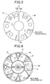
- FIG. 5 shows a cooling fan 12 according to the second embodiment of the invention.
- the cooling fan 12 is composed of a pair of cooling fan pieces 12A and 12B which are disposed on the same plane perpendicular to the axial direction of the rotating shaft 9 and each occupy one half of the entire angular range (i.e., 360°) of the cooling fan 12. Further, the cooling fan pieces 12A and 12B are separated from each other by an air gap 12C that extends in the radial direction of the rotating shaft 9.
- the positive electrode 19 and the negative electrode 20 are respectively brought into contact with the cooling fan pieces 12A and 12C from the opposite side to the pole core 10; then, the weld current is supplied to flow from the positive electrode 19 to the negative electrode 20.
- each of the projections 12c of the cooling fan pieces 12A and 12B can be supplied with the sufficient amount of the weld current, thereby preventing formation of a poor weld due to insufficient weld current.
- the cooling fan 12 is composed of the pair of cooling fan pieces 12A and 12B in the present embodiment.
- the cooling fan 12 may also be composed of more than two cooling fan pieces which are separated from each other by radial air gaps formed therebetween and each of which only contacts with electrodes having the same polarity.
- FIG. 6 shows a cooling fan 12 according to the third embodiment of the invention.
- the cooling fan 12 has a plurality of cuts (or slits) 21 each of which is formed between a circumferentially-adjacent pair of the blade portions 12a of the cooling fan 12. Further, each of the cuts 21 is so deeply formed in the radial direction of the rotating shaft 9 as to reach the annular connecting portion 12b. As a result, the blade portions 12a of the cooling fan 12 are connected to each other only by the annular connecting portion 12b.
- the blade portions 12a are connected to each other not only by the annular connecting portion 12b but also by root parts of the blade portions 12a which are integrally formed without cuts 21 formed therebetween.
- the positive and negative electrodes 19 and 20 are respectively brought into contact with two different ones of the blade portions 12a of the cooling fan 12; then, the weld current is supplied to flow from the positive electrode 19 to the negative electrode 20.
- each of the projections 12c of the cooling core 12 can be supplied with the sufficient amount of the weld current, thereby preventing formation of a poor weld due to insufficient weld current.
- the blade portions 12a of the cooling fan 12 are still connected to each other by the annular connecting portion 12b. Therefore, the cooling 12 can still be easily handled as a one-piece component of the rotor 3.
- FIG. 7A shows a pair of cooling fan pieces 12C and 12D according to the fourth embodiment of the invention.
- FIG. 7B shows a cooling fan 12 which is obtained by assembling the cooling fan pieces 12C and 12D together.
- each of the cooling fan pieces 12C and 12D includes a plurality of (e.g., four) blade portions 12a, which are equally spaced in the circumferential direction, and an annular connecting portion 12b that is located radially inside of the blade portions 12a to connect all of the blade portions 12a together.
- the cooling fan pieces 12C and 12D are assembled together so that: the blade portions 12a of the cooling fan piece 12C are alternately arranged with those of the cooling fan piece 12D in the circumferential direction of the rotating shaft 9; and the annular connecting portion 12b of the cooling fan piece 12C is overlapped with that of the cooling fan piece 12D in the axial direction of the rotating shaft 9. Furthermore, the annular connecting portions 12b of the cooling fan pieces 12C and 12D are electrically insulated from each other.
- the positive electrode 19 and the negative electrode 20 are respectively brought into contact with the cooling fan pieces 12C and 12D from the opposite side to the pole core 10; then, the weld current is supplied to flow from the positive electrode 19 to the negative electrode 20.
- each of the projections 12c of the cooling fan pieces 12C and 12D can be supplied with the sufficient amount of the weld current, thereby preventing formation of a poor weld due to insufficient weld current.
- all of the components of the rotor 3 other than the cooling fans 12 are first assembled together, and then the cooling fans 12 are respectively welded to the axial end faces of the pole cores 10.
Landscapes
- Engineering & Computer Science (AREA)
- Power Engineering (AREA)
- Mechanical Engineering (AREA)
- Manufacturing & Machinery (AREA)
- Manufacture Of Motors, Generators (AREA)
Applications Claiming Priority (1)
| Application Number | Priority Date | Filing Date | Title |
|---|---|---|---|
| JP2008241048A JP4683102B2 (ja) | 2008-09-19 | 2008-09-19 | 回転子の製造方法 |
Publications (3)
| Publication Number | Publication Date |
|---|---|
| EP2166643A2 true EP2166643A2 (de) | 2010-03-24 |
| EP2166643A3 EP2166643A3 (de) | 2012-09-19 |
| EP2166643B1 EP2166643B1 (de) | 2017-11-08 |
Family
ID=41511043
Family Applications (1)
| Application Number | Title | Priority Date | Filing Date |
|---|---|---|---|
| EP09011938.9A Active EP2166643B1 (de) | 2008-09-19 | 2009-09-18 | Verfahren zur herstellung des rotors einer dynamoelektrischen maschine |
Country Status (3)
| Country | Link |
|---|---|
| US (1) | US8429810B2 (de) |
| EP (1) | EP2166643B1 (de) |
| JP (1) | JP4683102B2 (de) |
Cited By (1)
| Publication number | Priority date | Publication date | Assignee | Title |
|---|---|---|---|---|
| CN108526671A (zh) * | 2018-05-30 | 2018-09-14 | 成都华川电装有限责任公司 | 发电机的爪极转子与风扇的焊接工装 |
Families Citing this family (5)
| Publication number | Priority date | Publication date | Assignee | Title |
|---|---|---|---|---|
| CN103433636B (zh) * | 2013-08-22 | 2015-08-05 | 唐勇 | 压焊复合法制造双金属冶金复合管的方法 |
| CN103624387B (zh) * | 2013-12-13 | 2015-12-09 | 株洲湘火炬火花塞有限责任公司 | 一种将汽车发电机冷却风扇叶焊接到转子上的焊接方法 |
| EP3742591B1 (de) * | 2018-01-18 | 2022-07-06 | Mitsubishi Electric Corporation | Rotor für eine elektrische drehmaschine für ein fahrzeug und verfahren zur herstellung davon |
| CN109676226B (zh) * | 2019-01-29 | 2024-04-19 | 宁国金鑫电机股份有限公司 | 一种汽车发电机转子风扇焊接整形工装 |
| CN112958893B (zh) * | 2021-02-07 | 2023-03-14 | 重庆宝优机电有限公司 | 转子点焊装置 |
Citations (3)
| Publication number | Priority date | Publication date | Assignee | Title |
|---|---|---|---|---|
| US20030222054A1 (en) | 2000-12-06 | 2003-12-04 | Toyota Shatai Kabushiki Kaisha | Series spot welding method, device for carrying out the method, and electrodes employed in the method or the device |
| WO2005072902A1 (ja) | 2004-01-30 | 2005-08-11 | Mitsubishi Denki Kabushiki Kaisha | 永久磁石材を有する金属部材の溶接装置及びその溶接方法並びに回転電機 |
| US20070001524A1 (en) | 2005-06-30 | 2007-01-04 | Denso Corporation | Alternator with a cooling fan rotated with a rotor |
Family Cites Families (5)
| Publication number | Priority date | Publication date | Assignee | Title |
|---|---|---|---|---|
| FR2685572B1 (fr) * | 1991-10-15 | 2003-01-10 | Mitsubishi Electric Corp | Generateur de courant pour vehicule, et procede de fabrication des ventilateurs. |
| EP1219379A3 (de) * | 1996-09-11 | 2002-07-17 | Miyachi Technos Corporation | Verfahren und Gerät zum Steuern des Widerstandsschweissens |
| JPH1085947A (ja) * | 1996-09-11 | 1998-04-07 | Miyachi Technos Corp | 抵抗溶接制御方法及び装置 |
| JP4380163B2 (ja) * | 2003-01-23 | 2009-12-09 | ソニー株式会社 | リード端子及び電源装置 |
| US7274121B2 (en) * | 2005-03-04 | 2007-09-25 | Remy Inc. | Systems and methods for fastening internal cooling fans to claw-pole electro-mechanical machines |
-
2008
- 2008-09-19 JP JP2008241048A patent/JP4683102B2/ja active Active
-
2009
- 2009-09-17 US US12/585,543 patent/US8429810B2/en active Active
- 2009-09-18 EP EP09011938.9A patent/EP2166643B1/de active Active
Patent Citations (4)
| Publication number | Priority date | Publication date | Assignee | Title |
|---|---|---|---|---|
| US20030222054A1 (en) | 2000-12-06 | 2003-12-04 | Toyota Shatai Kabushiki Kaisha | Series spot welding method, device for carrying out the method, and electrodes employed in the method or the device |
| WO2005072902A1 (ja) | 2004-01-30 | 2005-08-11 | Mitsubishi Denki Kabushiki Kaisha | 永久磁石材を有する金属部材の溶接装置及びその溶接方法並びに回転電機 |
| US20070040458A1 (en) | 2004-01-30 | 2007-02-22 | Mitsubishi Denki Kabushiki Kaisha | Welding set of metal member including permanent magnet and welding method thereof, as well as electric rotating machine |
| US20070001524A1 (en) | 2005-06-30 | 2007-01-04 | Denso Corporation | Alternator with a cooling fan rotated with a rotor |
Cited By (2)
| Publication number | Priority date | Publication date | Assignee | Title |
|---|---|---|---|---|
| CN108526671A (zh) * | 2018-05-30 | 2018-09-14 | 成都华川电装有限责任公司 | 发电机的爪极转子与风扇的焊接工装 |
| CN108526671B (zh) * | 2018-05-30 | 2024-05-14 | 成都华川电装有限责任公司 | 发电机的爪极转子与风扇的焊接工装 |
Also Published As
| Publication number | Publication date |
|---|---|
| EP2166643B1 (de) | 2017-11-08 |
| JP4683102B2 (ja) | 2011-05-11 |
| US8429810B2 (en) | 2013-04-30 |
| EP2166643A3 (de) | 2012-09-19 |
| JP2010074982A (ja) | 2010-04-02 |
| US20100071196A1 (en) | 2010-03-25 |
Similar Documents
| Publication | Publication Date | Title |
|---|---|---|
| US9419484B2 (en) | Stator for rotating electric machine | |
| US8772995B2 (en) | Stator for electric rotating machine | |
| JP5367362B2 (ja) | シャフトと磁極部材の間に中間スリーブが配置された回転電気機械用ロータ、およびロータの製造方法 | |
| US8429810B2 (en) | Method of manufacturing rotor for dynamoelectric machine | |
| US9748811B2 (en) | Stator for rotating electric machine | |
| CN109478814B (zh) | 旋转电机的定子和旋转电机 | |
| KR20120112395A (ko) | 자석 및 여자 코일용 절연체를 구비한 클로 로터, 및 이러한 로터를 갖춘 회전 전기 기계 | |
| JP2003259583A (ja) | 回転電機の固定子とその製造方法 | |
| US20070273243A1 (en) | Automotive alternator having improved structure for effectively cooling field coil | |
| US20150076945A1 (en) | Stator for rotating electric machine | |
| JP4734159B2 (ja) | 回転電機のステータの製造方法 | |
| US9705384B2 (en) | Rotor for rotating electric machine | |
| CN114651387B (zh) | 旋转电机的定子的制造方法、旋转电机的定子以及旋转电机 | |
| EP3716447A1 (de) | Generatoren mit flachdrahtwicklungen und verfahren zur herstellung von generatoren mit flachdrahtwicklungen | |
| US20140154086A1 (en) | Front fan retention in dual internal fan alternator | |
| WO2012077215A1 (ja) | 車両用交流発電機 | |
| GB1560746A (en) | Electrical machines | |
| US20190319521A1 (en) | Rotor and rotating electric machine including rotor | |
| US9041262B2 (en) | Stator for electric rotating machine | |
| WO2017110360A1 (ja) | 固定子、回転電機および固定子の製造方法 | |
| US20170353074A1 (en) | Rotor for rotating electric machine | |
| US20060113861A1 (en) | Motor vehicle AC generator having a rotor incorporating a field winding and permanent magnets | |
| JP2007295764A (ja) | 回転電機のステータ及びその製造方法及び交流発電機 | |
| JP2009055738A (ja) | 回転電機用回転子の冷却ファンの溶接方法 | |
| CN116264420A (zh) | 用于旋转电机的转子 |
Legal Events
| Date | Code | Title | Description |
|---|---|---|---|
| PUAI | Public reference made under article 153(3) epc to a published international application that has entered the european phase |
Free format text: ORIGINAL CODE: 0009012 |
|
| AK | Designated contracting states |
Kind code of ref document: A2 Designated state(s): AT BE BG CH CY CZ DE DK EE ES FI FR GB GR HR HU IE IS IT LI LT LU LV MC MK MT NL NO PL PT RO SE SI SK SM TR |
|
| AX | Request for extension of the european patent |
Extension state: AL BA RS |
|
| REG | Reference to a national code |
Ref country code: DE Ref legal event code: R079 Ref document number: 602009049217 Country of ref document: DE Free format text: PREVIOUS MAIN CLASS: H02K0001220000 Ipc: H02K0015020000 |
|
| PUAL | Search report despatched |
Free format text: ORIGINAL CODE: 0009013 |
|
| AK | Designated contracting states |
Kind code of ref document: A3 Designated state(s): AT BE BG CH CY CZ DE DK EE ES FI FR GB GR HR HU IE IS IT LI LT LU LV MC MK MT NL NO PL PT RO SE SI SK SM TR |
|
| AX | Request for extension of the european patent |
Extension state: AL BA RS |
|
| RIC1 | Information provided on ipc code assigned before grant |
Ipc: B23K 11/00 20060101ALI20120810BHEP Ipc: H02K 15/02 20060101AFI20120810BHEP Ipc: H02K 9/06 20060101ALI20120810BHEP Ipc: B23K 11/11 20060101ALI20120810BHEP |
|
| 17P | Request for examination filed |
Effective date: 20130319 |
|
| 17Q | First examination report despatched |
Effective date: 20130620 |
|
| GRAP | Despatch of communication of intention to grant a patent |
Free format text: ORIGINAL CODE: EPIDOSNIGR1 |
|
| STAA | Information on the status of an ep patent application or granted ep patent |
Free format text: STATUS: GRANT OF PATENT IS INTENDED |
|
| INTG | Intention to grant announced |
Effective date: 20170518 |
|
| GRAS | Grant fee paid |
Free format text: ORIGINAL CODE: EPIDOSNIGR3 |
|
| GRAA | (expected) grant |
Free format text: ORIGINAL CODE: 0009210 |
|
| STAA | Information on the status of an ep patent application or granted ep patent |
Free format text: STATUS: THE PATENT HAS BEEN GRANTED |
|
| AK | Designated contracting states |
Kind code of ref document: B1 Designated state(s): AT BE BG CH CY CZ DE DK EE ES FI FR GB GR HR HU IE IS IT LI LT LU LV MC MK MT NL NO PL PT RO SE SI SK SM TR |
|
| REG | Reference to a national code |
Ref country code: GB Ref legal event code: FG4D |
|
| REG | Reference to a national code |
Ref country code: CH Ref legal event code: EP Ref country code: AT Ref legal event code: REF Ref document number: 945054 Country of ref document: AT Kind code of ref document: T Effective date: 20171115 |
|
| REG | Reference to a national code |
Ref country code: IE Ref legal event code: FG4D |
|
| REG | Reference to a national code |
Ref country code: DE Ref legal event code: R096 Ref document number: 602009049217 Country of ref document: DE |
|
| REG | Reference to a national code |
Ref country code: NL Ref legal event code: MP Effective date: 20171108 |
|
| REG | Reference to a national code |
Ref country code: LT Ref legal event code: MG4D |
|
| REG | Reference to a national code |
Ref country code: AT Ref legal event code: MK05 Ref document number: 945054 Country of ref document: AT Kind code of ref document: T Effective date: 20171108 |
|
| PG25 | Lapsed in a contracting state [announced via postgrant information from national office to epo] |
Ref country code: NL Free format text: LAPSE BECAUSE OF FAILURE TO SUBMIT A TRANSLATION OF THE DESCRIPTION OR TO PAY THE FEE WITHIN THE PRESCRIBED TIME-LIMIT Effective date: 20171108 Ref country code: SE Free format text: LAPSE BECAUSE OF FAILURE TO SUBMIT A TRANSLATION OF THE DESCRIPTION OR TO PAY THE FEE WITHIN THE PRESCRIBED TIME-LIMIT Effective date: 20171108 Ref country code: ES Free format text: LAPSE BECAUSE OF FAILURE TO SUBMIT A TRANSLATION OF THE DESCRIPTION OR TO PAY THE FEE WITHIN THE PRESCRIBED TIME-LIMIT Effective date: 20171108 Ref country code: LT Free format text: LAPSE BECAUSE OF FAILURE TO SUBMIT A TRANSLATION OF THE DESCRIPTION OR TO PAY THE FEE WITHIN THE PRESCRIBED TIME-LIMIT Effective date: 20171108 Ref country code: FI Free format text: LAPSE BECAUSE OF FAILURE TO SUBMIT A TRANSLATION OF THE DESCRIPTION OR TO PAY THE FEE WITHIN THE PRESCRIBED TIME-LIMIT Effective date: 20171108 Ref country code: NO Free format text: LAPSE BECAUSE OF FAILURE TO SUBMIT A TRANSLATION OF THE DESCRIPTION OR TO PAY THE FEE WITHIN THE PRESCRIBED TIME-LIMIT Effective date: 20180208 |
|
| PG25 | Lapsed in a contracting state [announced via postgrant information from national office to epo] |
Ref country code: IS Free format text: LAPSE BECAUSE OF FAILURE TO SUBMIT A TRANSLATION OF THE DESCRIPTION OR TO PAY THE FEE WITHIN THE PRESCRIBED TIME-LIMIT Effective date: 20180308 Ref country code: BG Free format text: LAPSE BECAUSE OF FAILURE TO SUBMIT A TRANSLATION OF THE DESCRIPTION OR TO PAY THE FEE WITHIN THE PRESCRIBED TIME-LIMIT Effective date: 20180208 Ref country code: AT Free format text: LAPSE BECAUSE OF FAILURE TO SUBMIT A TRANSLATION OF THE DESCRIPTION OR TO PAY THE FEE WITHIN THE PRESCRIBED TIME-LIMIT Effective date: 20171108 Ref country code: GR Free format text: LAPSE BECAUSE OF FAILURE TO SUBMIT A TRANSLATION OF THE DESCRIPTION OR TO PAY THE FEE WITHIN THE PRESCRIBED TIME-LIMIT Effective date: 20180209 Ref country code: HR Free format text: LAPSE BECAUSE OF FAILURE TO SUBMIT A TRANSLATION OF THE DESCRIPTION OR TO PAY THE FEE WITHIN THE PRESCRIBED TIME-LIMIT Effective date: 20171108 Ref country code: LV Free format text: LAPSE BECAUSE OF FAILURE TO SUBMIT A TRANSLATION OF THE DESCRIPTION OR TO PAY THE FEE WITHIN THE PRESCRIBED TIME-LIMIT Effective date: 20171108 |
|
| PG25 | Lapsed in a contracting state [announced via postgrant information from national office to epo] |
Ref country code: SK Free format text: LAPSE BECAUSE OF FAILURE TO SUBMIT A TRANSLATION OF THE DESCRIPTION OR TO PAY THE FEE WITHIN THE PRESCRIBED TIME-LIMIT Effective date: 20171108 Ref country code: CZ Free format text: LAPSE BECAUSE OF FAILURE TO SUBMIT A TRANSLATION OF THE DESCRIPTION OR TO PAY THE FEE WITHIN THE PRESCRIBED TIME-LIMIT Effective date: 20171108 Ref country code: CY Free format text: LAPSE BECAUSE OF FAILURE TO SUBMIT A TRANSLATION OF THE DESCRIPTION OR TO PAY THE FEE WITHIN THE PRESCRIBED TIME-LIMIT Effective date: 20171108 Ref country code: EE Free format text: LAPSE BECAUSE OF FAILURE TO SUBMIT A TRANSLATION OF THE DESCRIPTION OR TO PAY THE FEE WITHIN THE PRESCRIBED TIME-LIMIT Effective date: 20171108 Ref country code: DK Free format text: LAPSE BECAUSE OF FAILURE TO SUBMIT A TRANSLATION OF THE DESCRIPTION OR TO PAY THE FEE WITHIN THE PRESCRIBED TIME-LIMIT Effective date: 20171108 |
|
| REG | Reference to a national code |
Ref country code: DE Ref legal event code: R097 Ref document number: 602009049217 Country of ref document: DE |
|
| PG25 | Lapsed in a contracting state [announced via postgrant information from national office to epo] |
Ref country code: RO Free format text: LAPSE BECAUSE OF FAILURE TO SUBMIT A TRANSLATION OF THE DESCRIPTION OR TO PAY THE FEE WITHIN THE PRESCRIBED TIME-LIMIT Effective date: 20171108 Ref country code: IT Free format text: LAPSE BECAUSE OF FAILURE TO SUBMIT A TRANSLATION OF THE DESCRIPTION OR TO PAY THE FEE WITHIN THE PRESCRIBED TIME-LIMIT Effective date: 20171108 Ref country code: SM Free format text: LAPSE BECAUSE OF FAILURE TO SUBMIT A TRANSLATION OF THE DESCRIPTION OR TO PAY THE FEE WITHIN THE PRESCRIBED TIME-LIMIT Effective date: 20171108 Ref country code: PL Free format text: LAPSE BECAUSE OF FAILURE TO SUBMIT A TRANSLATION OF THE DESCRIPTION OR TO PAY THE FEE WITHIN THE PRESCRIBED TIME-LIMIT Effective date: 20171108 |
|
| PLBE | No opposition filed within time limit |
Free format text: ORIGINAL CODE: 0009261 |
|
| STAA | Information on the status of an ep patent application or granted ep patent |
Free format text: STATUS: NO OPPOSITION FILED WITHIN TIME LIMIT |
|
| REG | Reference to a national code |
Ref country code: FR Ref legal event code: PLFP Year of fee payment: 10 |
|
| 26N | No opposition filed |
Effective date: 20180809 |
|
| PG25 | Lapsed in a contracting state [announced via postgrant information from national office to epo] |
Ref country code: SI Free format text: LAPSE BECAUSE OF FAILURE TO SUBMIT A TRANSLATION OF THE DESCRIPTION OR TO PAY THE FEE WITHIN THE PRESCRIBED TIME-LIMIT Effective date: 20171108 |
|
| PG25 | Lapsed in a contracting state [announced via postgrant information from national office to epo] |
Ref country code: MC Free format text: LAPSE BECAUSE OF FAILURE TO SUBMIT A TRANSLATION OF THE DESCRIPTION OR TO PAY THE FEE WITHIN THE PRESCRIBED TIME-LIMIT Effective date: 20171108 |
|
| REG | Reference to a national code |
Ref country code: CH Ref legal event code: PL |
|
| GBPC | Gb: european patent ceased through non-payment of renewal fee |
Effective date: 20180918 |
|
| REG | Reference to a national code |
Ref country code: BE Ref legal event code: MM Effective date: 20180930 |
|
| REG | Reference to a national code |
Ref country code: IE Ref legal event code: MM4A |
|
| PG25 | Lapsed in a contracting state [announced via postgrant information from national office to epo] |
Ref country code: LU Free format text: LAPSE BECAUSE OF NON-PAYMENT OF DUE FEES Effective date: 20180918 |
|
| PG25 | Lapsed in a contracting state [announced via postgrant information from national office to epo] |
Ref country code: IE Free format text: LAPSE BECAUSE OF NON-PAYMENT OF DUE FEES Effective date: 20180918 |
|
| PG25 | Lapsed in a contracting state [announced via postgrant information from national office to epo] |
Ref country code: BE Free format text: LAPSE BECAUSE OF NON-PAYMENT OF DUE FEES Effective date: 20180930 Ref country code: LI Free format text: LAPSE BECAUSE OF NON-PAYMENT OF DUE FEES Effective date: 20180930 Ref country code: CH Free format text: LAPSE BECAUSE OF NON-PAYMENT OF DUE FEES Effective date: 20180930 |
|
| PG25 | Lapsed in a contracting state [announced via postgrant information from national office to epo] |
Ref country code: GB Free format text: LAPSE BECAUSE OF NON-PAYMENT OF DUE FEES Effective date: 20180918 |
|
| PG25 | Lapsed in a contracting state [announced via postgrant information from national office to epo] |
Ref country code: MT Free format text: LAPSE BECAUSE OF NON-PAYMENT OF DUE FEES Effective date: 20180918 |
|
| PG25 | Lapsed in a contracting state [announced via postgrant information from national office to epo] |
Ref country code: TR Free format text: LAPSE BECAUSE OF FAILURE TO SUBMIT A TRANSLATION OF THE DESCRIPTION OR TO PAY THE FEE WITHIN THE PRESCRIBED TIME-LIMIT Effective date: 20171108 |
|
| PG25 | Lapsed in a contracting state [announced via postgrant information from national office to epo] |
Ref country code: HU Free format text: LAPSE BECAUSE OF FAILURE TO SUBMIT A TRANSLATION OF THE DESCRIPTION OR TO PAY THE FEE WITHIN THE PRESCRIBED TIME-LIMIT; INVALID AB INITIO Effective date: 20090918 Ref country code: PT Free format text: LAPSE BECAUSE OF FAILURE TO SUBMIT A TRANSLATION OF THE DESCRIPTION OR TO PAY THE FEE WITHIN THE PRESCRIBED TIME-LIMIT Effective date: 20171108 |
|
| PG25 | Lapsed in a contracting state [announced via postgrant information from national office to epo] |
Ref country code: MK Free format text: LAPSE BECAUSE OF NON-PAYMENT OF DUE FEES Effective date: 20171108 |
|
| PGFP | Annual fee paid to national office [announced via postgrant information from national office to epo] |
Ref country code: DE Payment date: 20250919 Year of fee payment: 17 |
|
| PGFP | Annual fee paid to national office [announced via postgrant information from national office to epo] |
Ref country code: FR Payment date: 20250919 Year of fee payment: 17 |