EP2166671A2 - Procédé et appareil pour la génération d'un signal à haute fréquence de très haute précision et indicateur de niveau correspondant - Google Patents
Procédé et appareil pour la génération d'un signal à haute fréquence de très haute précision et indicateur de niveau correspondant Download PDFInfo
- Publication number
- EP2166671A2 EP2166671A2 EP09169962A EP09169962A EP2166671A2 EP 2166671 A2 EP2166671 A2 EP 2166671A2 EP 09169962 A EP09169962 A EP 09169962A EP 09169962 A EP09169962 A EP 09169962A EP 2166671 A2 EP2166671 A2 EP 2166671A2
- Authority
- EP
- European Patent Office
- Prior art keywords
- signal
- output signal
- phase
- frequency
- control loop
- Prior art date
- Legal status (The legal status is an assumption and is not a legal conclusion. Google has not performed a legal analysis and makes no representation as to the accuracy of the status listed.)
- Granted
Links
Images

Classifications
-
- H—ELECTRICITY
- H03—ELECTRONIC CIRCUITRY
- H03L—AUTOMATIC CONTROL, STARTING, SYNCHRONISATION OR STABILISATION OF GENERATORS OF ELECTRONIC OSCILLATIONS OR PULSES
- H03L7/00—Automatic control of frequency or phase; Synchronisation
- H03L7/06—Automatic control of frequency or phase; Synchronisation using a reference signal applied to a frequency- or phase-locked loop
- H03L7/16—Indirect frequency synthesis, i.e. generating a desired one of a number of predetermined frequencies using a frequency- or phase-locked loop
- H03L7/22—Indirect frequency synthesis, i.e. generating a desired one of a number of predetermined frequencies using a frequency- or phase-locked loop using more than one loop
-
- G—PHYSICS
- G01—MEASURING; TESTING
- G01F—MEASURING VOLUME, VOLUME FLOW, MASS FLOW OR LIQUID LEVEL; METERING BY VOLUME
- G01F23/00—Indicating or measuring liquid level or level of fluent solid material, e.g. indicating in terms of volume or indicating by means of an alarm
- G01F23/22—Indicating or measuring liquid level or level of fluent solid material, e.g. indicating in terms of volume or indicating by means of an alarm by measuring physical variables, other than linear dimensions, pressure or weight, dependent on the level to be measured, e.g. by difference of heat transfer of steam or water
- G01F23/28—Indicating or measuring liquid level or level of fluent solid material, e.g. indicating in terms of volume or indicating by means of an alarm by measuring physical variables, other than linear dimensions, pressure or weight, dependent on the level to be measured, e.g. by difference of heat transfer of steam or water by measuring the variations of parameters of electromagnetic or acoustic waves applied directly to the liquid or fluent solid material
- G01F23/284—Electromagnetic waves
-
- H—ELECTRICITY
- H03—ELECTRONIC CIRCUITRY
- H03L—AUTOMATIC CONTROL, STARTING, SYNCHRONISATION OR STABILISATION OF GENERATORS OF ELECTRONIC OSCILLATIONS OR PULSES
- H03L7/00—Automatic control of frequency or phase; Synchronisation
- H03L7/06—Automatic control of frequency or phase; Synchronisation using a reference signal applied to a frequency- or phase-locked loop
- H03L7/16—Indirect frequency synthesis, i.e. generating a desired one of a number of predetermined frequencies using a frequency- or phase-locked loop
- H03L7/18—Indirect frequency synthesis, i.e. generating a desired one of a number of predetermined frequencies using a frequency- or phase-locked loop using a frequency divider or counter in the loop
- H03L7/183—Indirect frequency synthesis, i.e. generating a desired one of a number of predetermined frequencies using a frequency- or phase-locked loop using a frequency divider or counter in the loop a time difference being used for locking the loop, the counter counting between fixed numbers or the frequency divider dividing by a fixed number
- H03L7/185—Indirect frequency synthesis, i.e. generating a desired one of a number of predetermined frequencies using a frequency- or phase-locked loop using a frequency divider or counter in the loop a time difference being used for locking the loop, the counter counting between fixed numbers or the frequency divider dividing by a fixed number using a mixer in the loop
-
- H—ELECTRICITY
- H03—ELECTRONIC CIRCUITRY
- H03L—AUTOMATIC CONTROL, STARTING, SYNCHRONISATION OR STABILISATION OF GENERATORS OF ELECTRONIC OSCILLATIONS OR PULSES
- H03L2207/00—Indexing scheme relating to automatic control of frequency or phase and to synchronisation
- H03L2207/10—Indirect frequency synthesis using a frequency multiplier in the phase-locked loop or in the reference signal path
-
- H—ELECTRICITY
- H03—ELECTRONIC CIRCUITRY
- H03L—AUTOMATIC CONTROL, STARTING, SYNCHRONISATION OR STABILISATION OF GENERATORS OF ELECTRONIC OSCILLATIONS OR PULSES
- H03L2207/00—Indexing scheme relating to automatic control of frequency or phase and to synchronisation
- H03L2207/12—Indirect frequency synthesis using a mixer in the phase-locked loop
Definitions
- This disclosure relates generally to inventory management systems. More specifically, this disclosure relates to a method and apparatus for highly accurate higher frequency signal generation and related level gauge.
- Processing facilities and other facilities routinely include tanks for storing liquid materials and other materials.
- storage tanks are routinely used in tank farm facilities and other storage facilities to store oil or other materials.
- oil tankers and other transport vessels routinely include numerous tanks storing oil or other materials.
- VCOs voltage-controlled oscillators
- MMW millimeter waves
- a phase-locked loop can be used to stabilize a voltage-controlled oscillator by forming a closed loop so that a frequency produced by the voltage-controlled oscillator is relatively stable or "locked.”
- This solution is effective if the frequency range of the voltage-controlled oscillator can be covered by the phase-locked loop's bandwidth. This is typically true for the frequency range below 10GHz because of limitations of current phase-locked loop chips.
- a dielectric resonance oscillator DRO
- dielectric resonance oscillators are still susceptible to temperature variations, which results in variations of the locked frequencies.
- This disclosure provides a method and apparatus for highly accurate higher frequency signal generation and related level gauge.
- an apparatus in a first embodiment, includes a stable local oscillator, which includes a first control loop.
- the first control loop includes (i) a first voltage-controlled oscillator configured to generate a first output signal and (ii) a first phase-locked loop.
- the apparatus also includes a frequency up-converter configured to increase a frequency of the first output signal.
- the apparatus further includes a second control loop configured to receive the up-converted first output signal.
- the second control loop includes (i) a second voltage-controlled oscillator configured to generate a second output signal and (ii) a second phase-locked loop.
- a level gauge in a second embodiment, includes a sensor configured to transmit wireless signals towards material in a tank and receive wireless signals reflected off the material in the tank.
- the level gauge also includes a processing system configured to identify a level of the material in the tank based on the wireless signals transmitted towards and reflected off the material in the tank.
- the sensor includes a phase-locked loop based stable local oscillator configured to generate a first output signal and a phase-locked loop based control loop configured to generate a second output signal based on the first output signal.
- a method in a third embodiment, includes generating a first signal using a stable local oscillator that includes a first control loop.
- the first control loop includes a first voltage-controlled oscillator and a first phase-locked loop.
- the method also includes increasing a frequency of the first signal to produce an up-converted first signal.
- the method further includes generating a second signal based on the up-converted first signal using a second control loop.
- the second control loop includes a second voltage-controlled oscillator and a second phase-locked loop.
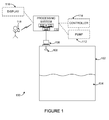
- FIGURE 1 illustrates an example tank level measurement system according to this disclosure
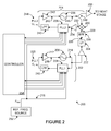
- FIGURE 2 illustrates an example multiple phase-locked loop (PLL) circuit for highly accurate signal generation according to this disclosure
- FIGURES 3A and 3B illustrate example adjustable power transmission control circuits using highly accurate signal generation according to this disclosure
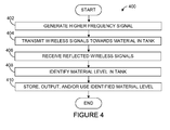
- FIGURE 4 illustrates an example method for level gauging using highly accurate signal generation according to this disclosure.
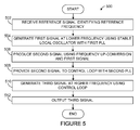
- FIGURE 5 illustrates an example method for highly accurate signal generation according to this disclosure.
- FIGURES 1 through 5 discussed below, and the various embodiments used to describe the principles of the present invention in this patent document are by way of illustration only and should not be construed in any way to limit the scope of the invention. Those skilled in the art will understand that the principles of the invention may be implemented in any type of suitably arranged device or system.
- FIGURE 1 illustrates an example tank level measurement system 100 according to this disclosure.
- the system 100 includes a tank 102 that can store one or more materials 104.
- the tank 102 generally represents any suitable structure for receiving and storing at least one liquid or other material.
- the tank 102 could, for example, represent an oil storage tank or a tank for storing other liquid(s) or other material(s).
- the tank 102 could also have any suitable shape and size.
- the tank 102 could form part of a larger structure.
- the larger structure could represent any fixed or movable structure containing or associated with one or more tanks 102, such as a movable tanker vessel, railcar, or truck or a fixed tank farm.
- a sensor 106 with at least one antenna 108 is used in conjunction with a processing system 110 to measure the level of material 104 in the tank 102.
- the antenna 108 emits electromagnetic waves or other wireless signals towards the material 104 and receives reflected signals from the material 104.
- the sensor 106 includes any suitable structure for generating signals for wireless transmission and for receiving reflected signals.
- the antenna 108 includes any suitable structure for transmitting and/or receiving wireless signals, such as a planar or horn antenna.
- Data from the sensor 106 is provided to the processing system 110.
- the processing system 110 can use the data from the sensor 106 in any suitable manner.
- the sensor 106 could provide data identifying the transmitted and reflected signals, and the processing system 110 can analyze the data to identify the level of the material 104 in the tank 102.
- the processing system 110 could also use the determined level in any suitable manner.
- the processing system 110 could control automatic loading or unloading of the tank 102 by controlling a pump 112 or by providing the determined level to an external controller 114 that controls the pump 112.
- the processing system 110 could also notify personnel responsible for controlling the loading or unloading of the tank 102, such as by displaying the determined level on a display 116 or transmitting the determined level to a wireless or other device 118.
- the processing system 110 could represent any suitable computing or processing system or device, such as a computing device, a process controller, or other system or device.
- the processing system 110 includes at least one processor 120 and at least one memory 122 storing instructions and data used, generated, or collected by the at least one processor 120.
- the processing system 110 can also include at least one interface 124 facilitating communication with external devices or systems like the components 106 and 112-118, such as an Ethernet interface, a radio frequency (RF) or other wireless interface, or a serial interface.
- RF radio frequency
- the sensor 106 generates wireless signals within a desired frequency band with high stability over a wide temperature range.
- PLL phased-lock loop
- STALO PLL-locked stable local oscillator
- This multi-PLL design can provide an extremely flexible architecture to generate very high frequencies that various applications and regulations require.
- This technique can also achieve high stability over a very wide temperature range and achieve better noise performance with fewer components (compared to traditional analog compensation techniques). In particular embodiments, this technique can be applied to radars or other higher-frequency hardware systems that need to provide high performance.
- FIGURE 2 One example implementation of a multi-PLL design that can be used in the sensor 106 is shown in FIGURE 2 , which is described below.
- the "level" of material 104 in a tank 102 could refer to the absolute level of the material 104 in the tank 102, such as when the level represents the distance between the top of the material 104 and the bottom of the tank 102.
- the "level” could also refer to the relative level of the material 104 in the tank 102, such as when the level represents the distance between the top of the material 104 and the antenna 112.
- FIGURE 1 illustrates an example tank level measurement system 100
- the system 100 could include any number of tanks 102, sensors 106, processing systems 110, and other components.
- the functional division shown in FIGURE 1 is for illustration only.
- Various components in FIGURE 1 could be omitted, combined, or further subdivided and additional components could be added according to particular needs.
- the processing system 110 could be integrated into (form a part of) the sensor 106.
- FIGURE 2 illustrates an example multiple phase-locked loop (PLL) circuit 200 for highly accurate signal generation according to this disclosure. More specifically, this circuit 200 implements a PLL-based stable local oscillator 202, which produces a signal used as an input to a PLL-based control loop 204.
- PLL phase-locked loop
- the PLL-based stable local oscillator 202 includes a voltage-controlled oscillator 206, a first phase-locked loop (PLL1) module 208, a low-pass filter (LPF) 210, and an amplifier 212.
- the voltage-controlled oscillator 206 operates to produce a signal 214, which is provided to the PLL-based control loop 204.
- the voltage-controlled oscillator 206 includes any suitable structure for generating a signal having a frequency based on an input voltage.
- the phase-locked loop module 208, the filter 210, and the amplifier 212 operate to generate a tuning voltage 216 that is provided to the voltage-controlled oscillator 206.
- the phase-locked loop module 208 includes any suitable structure for generating a signal having a stable frequency based on feedback.
- the phase-locked loop module 208 could, for example, include a phase comparator for comparing the phase of the signal 214 to the phase of a signal 218 having a reference frequency (F REF ).
- the filter 210 includes any suitable structure for filtering a signal with an appropriate passband.
- the amplifier 212 includes any suitable structure for providing amplification based on a first control voltage (PLL1 V CTRL ) 220, which in this example is based on the output of the filter 210.
- the control voltage 220 illustrates the flexible control of the tuning range of the voltage-controlled oscillator 206 by the first phase-locked loop module 208.
- the signal 214 produced by the PLL-based stable local oscillator 202 is provided to a buffer 222, which buffers the signal 214.
- the buffered signal 214 is provided to a frequency up-converter 224, which increases the frequency of the buffered signal 214 to produce an up-converted signal 226.
- the frequency up-converter 224 could increase the frequency of the signal 214 by a factor of two or four, although other factors could be used.
- the frequency up-converter 224 represents any suitable structure for increasing the frequency of a signal.
- the up-converted signal 226 is filtered by a bandpass filter (BPF) 228, which includes any suitable structure for filtering a signal with an appropriate passband.
- BPF bandpass filter
- the filtered signal 229 is provided to the PLL-based control loop 204. More specifically, the filtered signal 229 is provided to one input of a mixer 230, which mixes the filtered signal 229 with another signal to produce a mixed signal 232.
- the mixer 230 includes any suitable structure for mixing signals.
- the mixed signal 232 is amplified by an amplifier 234, which represents any suitable structure for providing amplification.
- the PLL-based control loop 204 also includes a voltage-controlled oscillator 236, a second phase-locked loop (PPL2) module 238, a low-pass filter 240, and an amplifier 242 controlled by a second control voltage (PPL2 V CTRL ) 244, which in this example is based on the output of the filter 240.
- the control voltage 244 illustrates the flexible control of the tuning range of the voltage-controlled oscillator 236 by the second phase-locked loop module 238.
- These components 236-242 have the same or similar functionality as the corresponding components 206-212 described above (except the components 236-242 handle signals at higher frequencies).
- the amplifier 242 produces a tuning voltage 243 for the voltage-controlled oscillator 236.
- a signal 246 produced by the voltage-controlled oscillator 236 is provided via a divider, coupler, or splitter 248 to the second input of the mixer 230, as well as to a buffer 250.
- the buffer 250 buffers the signal 246 before providing the buffered signal to a subsequent stage.
- the subsequent stage could represent a stage designed to use the signal 246 for transmission or a stage designed to further increase the frequency of the signal 246.
- the subsequent stage could, for example, include a copy of the components 224-250, where the output of the buffer 250 in FIGURE 2 is coupled to the input of the frequency up-converter 224 in the subsequent stage.
- the output of the circuit 200 can be inserted/cascaded as a STALO for higher frequency up-conversion using the same PLL-based circuit (PLL2 as illustrated). This may be useful when even higher frequencies are desired or required.
- the circuit 200 can be used as an input of direct frequency multiplication or as a direct output to an antenna system for signal radiation.
- the PLL-based stable local oscillator 202 could be used to produce a highly stable 20GHz signal, and the frequency up-converter 224 could use the 20GHz signal to produce a 60GHz or 80GHz signal used by the PLL-based control loop 204.
- Conventional 60GHz or 80GHz free running oscillators are very expensive.
- the use of a dielectric resonance oscillator (DRO) in place of the PLL-based stable local oscillator 202 would allow for the creation of errors, which would lead to the creation of even larger errors in the signal 226 due to the multiplication effect by the frequency up-converter 224.
- DRO dielectric resonance oscillator
- circuit 200 shown in FIGURE 2 helps to overcome drawbacks of using DRO-like oscillators at higher frequencies (since the DRO has temperature-dependent characteristics).
- the circuit 200 shown in FIGURE 2 can generate highly-stable higher-frequency signals using standard off-the-shelf components
- a single frequency reference source 252 (such as a stable local reference oscillator) can be used for all of the PLLs. This may allow the variation of the frequency band caused by the temperature dependence of the reference oscillator to be handled more easily.
- COTS commercial off-the-shelf
- TCXO temperature-compensated crystal oscillator
- ppm parts per million
- the multi-PLL circuit 200 can select a single TCXO as a reference input in a way that the variation of the sweep bandwidth or of the generated frequency can be controlled in a simple manner. This allows higher accuracy of level measurements to be attained.
- a controller 254 provides control signals to at least the phase-locked loop modules 208 and 238.
- each of the phase-locked loop modules 208 and 238 is implemented using a COTS chip, and the controller 254 provides three standard control signals to each phase-locked loop.
- Each phase-locked loop module 208 and 238 can also provide a lock detection signal indicating that a frequency has been locked to the controller 254.
- the controller 254 could control any other aspects of the circuit 200.
- the controller 254 includes any suitable structure for controlling operation of the circuit 200.
- the controller 254 could represent a processor, microprocessor, microcontroller, field programmable gate array, digital signal processor, complex programmable logic device, or other processing or control device.
- the PLL control voltages can be arranged in several ways to produce different frequency modulation schemes and waveforms. For example, to generate a stepped-frequency continuous-wave, one control voltage input can be varied to cover the desired frequency band, and other control voltage input(s) can be fixed as constant(s) to provide a constant STALO frequency signal. As another example, two PLLs may vary in a way that allows a specific frequency coding to be generated. This makes the circuit 200 extremely flexible in locked frequency generation for stepped-frequency continuous-wave radar systems, as well as for other systems (such as frequency hopping).
- One possible modulation scheme involves digital control by the controller 254, which can make higher frequency analog components extremely stable and consistent over a wide range of temperature variations. In this way, the frequencies, bandwidth, and coding sequence can be easily and flexibly adjusted before or during the operation of the circuit 200, such as by programming the controller 254.
- One particular implementation can be used as a software-defined radio system, which can be flexibly accommodated to various national and international regulations.
- FIGURE 2 illustrates an example multiple phase-locked loop circuit 200 for highly accurate signal generation
- various changes may be made to FIGURE 2 .
- multiple stages could be used here, depending on the desired or required frequency of the output signal.
- the implementations of the PLL-based stable local oscillator 202 and the PLL-based control loop 204 are for illustration only.
- FIGURES 3A and 3B illustrate example adjustable power transmission control circuits 300 and 350 using highly accurate signal generation according to this disclosure.
- the adjustable power transmission control circuit 300 includes an amplifier 302, which receives and amplifies a signal provided by a prior stage (such as a signal provided by the circuit 200).
- the amplified signal is provided through a splitter or divider 304 to a variable attenuator 306, which operates to reduce the power of the amplified signal based on a control signal 308 from the controller 254.
- the attenuated signal is then provided via a splitter, coupler, switch, or duplexer 310 to an antenna 312 for transmission.
- the amplified signal from the amplifier 302 is also provided through the splitter or divider 304 to a variable attenuator 314, which also operates to reduce the power of the amplified signal based on a control signal 316 from the controller 254.
- the attenuated signal from the variable attenuator 314 is provided to an amplifier 318, which amplifies the signal as a local oscillator to drive the mixer 320.
- a mixer 320 mixes the amplified signal with received signals provided by the antenna 312 through the splitter, coupler, switch, or duplexer 310.
- a conditioner 319 such as a low noise amplifier (LNA), can be used before the mixer 320 to process the signals provided by the antenna 312.
- LNA low noise amplifier
- the mixed signal produced by the mixer 320 is provided to a bandpass filter 322, which filters the signal.
- the filtered signal can be provided to components in an additional stage, such as an amplifier, a lower-frequency analog-to-digital converter, or other components in the "receive path" of a device.
- Each of the variable attenuators 306 and 314 includes any suitable structure for providing variable attenuation controlled separately by a controller.
- Each of the amplifiers 302 and 318 includes any suitable structure for providing amplification.
- Each of the splitters, couplers, switches, duplexers, or dividers 304 and 310 includes any suitable structure for dividing access to one or more components.
- the antenna 312 includes any suitable structure for transmitting and/or receiving wireless signals.
- the mixer 320 includes any suitable structure for mixing signals.
- the filter 322 includes any suitable structure for filtering a signal with an appropriate passband.
- the adjustable power transmission control circuit 350 includes many of the same components 352-358 and 362-372 as shown in FIGURE 3A .
- the variable attenuator 356 is provided with an additional amplifier 374. This combination can also be used to compensate for some upper spectral loss.
- a directional coupler 360 is used to provide an input to the mixer 370.
- a portion of the energy transmitted to or from the antenna 362 can be coupled to the mixer 370 by the directional coupler 360.
- variable attenuators are used and controlled by the controller 254.
- the variable attenuators are used to control both the radiated power level of a device and the processing of received signals.
- the radiated power level of the device can be set in accordance with different applications, environments, and regulations. Since both the frequency spectrum and the power of the generated signals can be digitally controlled, radar systems and other systems can be made more flexible and accurate with consistent performance.
- FIGURES 3A and 3B illustrate example adjustable power transmission control circuits 300 and 350 using highly accurate signal generation
- the controller in FIGURES 3A and 3B need not necessarily represent the same controller 254 used in FIGURE 2 .
- a highly accurate signal is used here for both transmission and reception, the highly accurate signal from the prior stage could be used for either transmission or reception.
- a device could include only a transmission path or only a receive path if the device represents a transmit-only device or a receive-only device.
- FIGURE 4 illustrates an example method 400 for level gauging using highly accurate signal generation according to this disclosure.
- an accurate higher-frequency signal is generated at step 402. This could include, for example, the sensor 106 using the multiple PLL circuit 200 of FIGURE 2 to generate a 20GHz, 60GHZ, or 80GHz wideband signal with high accuracy, regardless of temperature or transmission power level.
- Wireless signals are transmitted towards material in a tank at step 404, and reflected signals are received at step 406.
- This could include, for example, the sensor 106 generating wireless signals that are transmitted from the antenna 108 towards the material 104 in the tank 102 and receiving wireless signals reflected from, among other things, the material 104.
- the wireless signals transmitted to the material 104 could be generated using the highly accurate signal produced at step 402, and/or the wireless signals received from the material 104 could be processed using the highly accurate signal produced at step 402.
- the level of material in the tank is identified at step 408. This could include, for example, the processing system 110 using time of flight or other techniques used in level gauges to calculate the level of material 104 in the tank 102.
- the identified level is stored, output, and/or used in any suitable manner at step 410. This could include, for example, the processing system 110 displaying the identified level, storing the identified level in a memory, or transmitting messages containing the identified level.
- FIGURE 4 illustrates an example method 400 for level gauging using highly accurate signal generation
- various changes may be made to FIGURE 4 .
- steps in FIGURE 4 may overlap, occur in parallel, or occur multiple times.
- FIGURE 5 illustrates an example method 500 for highly accurate signal generation according to this disclosure.
- a reference signal identifying a reference frequency is received at step 502. This could include, for example, the circuit 200 receiving the signal 218 defining a reference frequency.
- a first signal is generated at a lower frequency using a stable local oscillator with a first PLL at step 504.
- the signal 214 is generated by the voltage-controlled oscillator 206 using the phase-locked loop module 208, which receives the reference signal identifying the reference frequency.
- a second signal is generated using frequency up-conversion and the first signal at step 506.
- the frequency of the signal 214 could be increased by any suitable factor.
- the second signal is provided to a control loop with a second PLL at step 508. This could include, for example, providing the signal 226 to the mixer 230 in the PLL-based control loop 204.
- a third signal is generated at a higher frequency using the control loop at step 510.
- the signal 246 is generated by the voltage-controlled oscillator 236 using the phase-locked loop module 238, which receives the reference signal identifying the reference frequency.
- the third signal is output at step 512. This could include, for example, providing the signal 246 to one of the circuits 300 or 350 in FIGURE 3A or 3B or to any other suitable component or system.
- FIGURE 5 illustrates an example method 500 for highly accurate signal generation
- various changes may be made to FIGURE 5 .
- steps in FIGURE 5 may overlap, occur in parallel, or occur multiple times.
- various functions described above are implemented or supported by a computer program that is formed from computer readable program code and that is embodied in a computer readable medium.
- computer readable program code includes any type of computer code, including source code, object code, and executable code.
- computer readable medium includes any type of medium capable of being accessed by a computer, such as read only memory (ROM), random access memory (RAM), a hard disk drive, a compact disc (CD), a digital video disc (DVD), or any other type of memory.
- the terms “higher” and “lower” refer to relative values (such as relative frequencies) and do not involve any specific values or ranges of values.
- the term “couple” and its derivatives refer to any direct or indirect communication between two or more elements, whether or not those elements are in physical contact with one another.
- the terms “algorithm” and “program” refers to one or more computer programs, software components, sets of instructions, procedures, functions, objects, classes, instances, related data, or a portion thereof adapted for implementation in a suitable computer code (including source code, object code, or executable code).
- controller means any device, system, or part thereof that controls at least one operation.
- a controller may be implemented in hardware, firmware, software, or some combination of at least two of the same. The functionality associated with any particular controller may be centralized or distributed, whether locally or remotely.
Landscapes
- Physics & Mathematics (AREA)
- Electromagnetism (AREA)
- Thermal Sciences (AREA)
- Fluid Mechanics (AREA)
- General Physics & Mathematics (AREA)
- Stabilization Of Oscillater, Synchronisation, Frequency Synthesizers (AREA)
Applications Claiming Priority (2)
| Application Number | Priority Date | Filing Date | Title |
|---|---|---|---|
| US9814608P | 2008-09-18 | 2008-09-18 | |
| US12/534,723 US8659472B2 (en) | 2008-09-18 | 2009-08-03 | Method and apparatus for highly accurate higher frequency signal generation and related level gauge |
Publications (3)
| Publication Number | Publication Date |
|---|---|
| EP2166671A2 true EP2166671A2 (fr) | 2010-03-24 |
| EP2166671A3 EP2166671A3 (fr) | 2010-04-28 |
| EP2166671B1 EP2166671B1 (fr) | 2012-03-21 |
Family
ID=41350679
Family Applications (1)
| Application Number | Title | Priority Date | Filing Date |
|---|---|---|---|
| EP09169962A Active EP2166671B1 (fr) | 2008-09-18 | 2009-09-10 | Procédeé et appareil pour la génération d'un signal à haute fréquence de très haute précision et indicateur de niveau correspondant |
Country Status (3)
| Country | Link |
|---|---|
| US (1) | US8659472B2 (fr) |
| EP (1) | EP2166671B1 (fr) |
| AT (1) | ATE550831T1 (fr) |
Cited By (10)
| Publication number | Priority date | Publication date | Assignee | Title |
|---|---|---|---|---|
| WO2013044953A1 (fr) * | 2011-09-27 | 2013-04-04 | Rosemount Tank Radar Ab | Contrôle de niveau par radar avec détection d'une surface en mouvement |
| US8730093B2 (en) | 2011-09-27 | 2014-05-20 | Rosemount Tank Radar Ab | MFPW radar level gauging with distance approximation |
| WO2014135565A1 (fr) * | 2013-03-07 | 2014-09-12 | Rosemount Tank Radar Ab | Indicateur de niveau à radar fmcw à commande d'état de verrouillage |
| US8872694B2 (en) | 2010-12-30 | 2014-10-28 | Rosemount Tank Radar Ab | Radar level gauging using frequency modulated pulsed wave |
| US9513153B2 (en) | 2010-12-30 | 2016-12-06 | Rosemount Tank Radar Ab | Radar level gauging using frequency modulated pulsed wave |
| EP3255392A1 (fr) * | 2016-06-07 | 2017-12-13 | VEGA Grieshaber KG | Radar de niveau de remplissage destine a la formation de faisceaux cote emission au moyen de plls parallele |
| US20180031687A1 (en) * | 2016-08-01 | 2018-02-01 | Vega Grieshaber Kg | Radar fill level measurement device |
| CN108871500A (zh) * | 2017-05-09 | 2018-11-23 | Vega格里沙贝两合公司 | 包括锁相环的雷达料位测量装置及其用途和操作方法 |
| EP3418699A1 (fr) * | 2017-06-21 | 2018-12-26 | VEGA Grieshaber KG | Jauge radar à puissance d'émission commandée |
| US10866134B2 (en) | 2017-06-21 | 2020-12-15 | Vega Grieshaber Kg | Fill level measurement device having optimised energy consumption |
Families Citing this family (14)
| Publication number | Priority date | Publication date | Assignee | Title |
|---|---|---|---|---|
| NL1031209C2 (nl) * | 2006-02-22 | 2007-08-24 | Enraf Bv | Werkwijze en inrichting voor het nauwkeurig vaststellen van het niveau L van een vloeistof met behulp van naar het vloeistofniveau uitgestraalde radarsignalen en door het vloeistofniveau gereflecteerde radarsignalen. |
| NL1034327C2 (nl) * | 2007-09-04 | 2009-03-05 | Enraf Bv | Werkwijze en inrichting voor het binnen een bepaald meetbereik vaststellen van het niveau L van een vloeistof met behulp van naar het vloeistofniveau uitgestraalde radarsignalen en door het vloeistofniveau gereflecteerde radarsignalen. |
| US8271212B2 (en) * | 2008-09-18 | 2012-09-18 | Enraf B.V. | Method for robust gauging accuracy for level gauges under mismatch and large opening effects in stillpipes and related apparatus |
| US8224594B2 (en) * | 2008-09-18 | 2012-07-17 | Enraf B.V. | Apparatus and method for dynamic peak detection, identification, and tracking in level gauging applications |
| WO2013067594A1 (fr) * | 2011-11-11 | 2013-05-16 | The University Of Melbourne | Appareil et procédé permettant d'obtenir des informations concernant au moins une cible |
| US9046406B2 (en) | 2012-04-11 | 2015-06-02 | Honeywell International Inc. | Advanced antenna protection for radars in level gauging and other applications |
| US9991751B2 (en) | 2014-05-09 | 2018-06-05 | The Board Of Trustees Of The Leland Stanford Junior University | Short range wireless communication |
| DE102014111431B4 (de) | 2014-08-11 | 2024-07-11 | Infineon Technologies Ag | Flugzeitvorrichtungen |
| CN104655184B (zh) * | 2014-12-19 | 2017-09-19 | 山东应天节能环保科技有限公司 | 基于3d雷达的脱硫脱硝物料流速和余量检测装置及方法 |
| US9701323B2 (en) | 2015-04-06 | 2017-07-11 | Bedloe Industries Llc | Railcar coupler |
| WO2016170932A1 (fr) * | 2015-04-24 | 2016-10-27 | 三菱電機株式会社 | Dispositif et système de synchronisation de fréquence |
| DE102015219612A1 (de) * | 2015-10-09 | 2017-04-13 | Vega Grieshaber Kg | Systemarchitektur für einen MIMO Füllstandradar |
| DE102017207783B3 (de) * | 2017-05-09 | 2018-06-07 | Vega Grieshaber Kg | Radarfüllstandmessgerät mit einem Phasenregelkreis |
| US10914830B2 (en) * | 2017-10-12 | 2021-02-09 | Honeywell International Inc. | Digital active phased array radar |
Citations (5)
| Publication number | Priority date | Publication date | Assignee | Title |
|---|---|---|---|---|
| US4451930A (en) | 1982-08-02 | 1984-05-29 | Motorola Inc. | Phase-locked receiver with derived reference frequency |
| US5034703A (en) | 1989-07-20 | 1991-07-23 | Siemens Aktiengesellschaft | Frequency synthesizer |
| US6404288B1 (en) | 1999-11-03 | 2002-06-11 | Krohne A.G. | Time base generator |
| US20020183030A1 (en) | 2001-03-30 | 2002-12-05 | Morten Damgaard | Frequency plan |
| US20040207477A1 (en) | 2003-04-21 | 2004-10-21 | Gumm Linley F. | Phase lock for synthesizer phase reference oscillator |
Family Cites Families (88)
| Publication number | Priority date | Publication date | Assignee | Title |
|---|---|---|---|---|
| US3353104A (en) * | 1963-10-02 | 1967-11-14 | Ltv Electrosystems Inc | Frequency synthesizer using fractional division by digital techniques within a phase-locked loop |
| US3217267A (en) * | 1963-10-02 | 1965-11-09 | Ling Temco Vought Inc | Frequency synthesis using fractional division by digital techniques within a phase-locked loop |
| US3337814A (en) * | 1966-08-23 | 1967-08-22 | Collins Radio Co | Phase comparator for use in frequency synthesizer phase locked loop |
| US3579281A (en) * | 1969-06-04 | 1971-05-18 | Sierra Research Corp | Combining network providing compensated tuning voltage for varactor |
| US3789302A (en) * | 1972-03-31 | 1974-01-29 | Microwave Ass Inc | Fm heterodyne transmitter |
| IT986172B (it) * | 1973-06-18 | 1975-01-20 | Fatme Spa | Dispositivo di sincronizzazione automatica per un oscillatore in particolare per impianti di tele comunicazione |
| JPS513160A (fr) * | 1974-06-25 | 1976-01-12 | Matsushita Electric Industrial Co Ltd | |
| GB1444860A (en) * | 1974-12-12 | 1976-08-04 | Mullard Ltd | Frequency synthesiser |
| US4000476A (en) * | 1974-12-19 | 1976-12-28 | Digital Communications Corporation | Phase locked loop with circuit for preventing sidelock |
| US4072947A (en) * | 1976-11-11 | 1978-02-07 | Rca Corporation | Monotonically ranging FM-CW radar signal processor |
| US4068199A (en) * | 1976-12-23 | 1978-01-10 | Gte Sylvania Incorporated | Digital phase-locked loop frequency modulator |
| US4114110A (en) * | 1977-12-01 | 1978-09-12 | The United States Of America As Represented By The Secretary Of The Army | Frequency synthesizer |
| DE2928487A1 (de) * | 1979-07-14 | 1981-02-05 | Philips Patentverwaltung | Verfahren zur messung der relativen feuchte eines messgutes mit hilfe von mikrowellen im ghz-bereich |
| US4363030A (en) | 1979-11-30 | 1982-12-07 | Drexelbrook Engineering Company | Fail-safe instrument system |
| JPS5843632A (ja) * | 1981-09-01 | 1983-03-14 | テクトロニツクス・インコ−ポレイテツド | 位相固定回路 |
| US4567448A (en) * | 1982-08-05 | 1986-01-28 | Epson Corporation | Variable frequency oscillator |
| US4516084A (en) * | 1983-02-18 | 1985-05-07 | Rca Corporation | Frequency synthesizer using an arithmetic frequency synthesizer and plural phase locked loops |
| US4675617A (en) * | 1986-02-03 | 1987-06-23 | Martin Kenneth W | Stable voltage controlled oscillator |
| US4691176A (en) * | 1986-03-17 | 1987-09-01 | General Electric Company | Adaptive carrier tracking circuit |
| US5210539A (en) * | 1986-09-30 | 1993-05-11 | The Boeing Company | Linear frequency sweep synthesizer |
| GB8702804D0 (en) * | 1987-02-07 | 1987-03-11 | Schlumberger Electronics Uk | Frequency response analysis |
| US4823399A (en) * | 1987-07-30 | 1989-04-18 | General Instrument Corporation | Refined tuning of RF receiver with frequency-locked loop |
| US4800341A (en) * | 1987-11-02 | 1989-01-24 | Eaton Corporation | Fast switching frequency synthesizer |
| JPH02109486A (ja) * | 1988-10-19 | 1990-04-23 | Matsushita Electric Ind Co Ltd | 自動周波数切替装置 |
| US4928525A (en) | 1989-03-02 | 1990-05-29 | Aderholt Gary L | Sonic tank inventory control system and method |
| EP0389662B1 (fr) * | 1989-03-31 | 1993-11-03 | Siemens Aktiengesellschaft | Procédé de réglage de la phase des signaux de deux générateurs d'horloge dans les réseaux de télécommunications |
| US5027526A (en) | 1989-06-02 | 1991-07-02 | Crane R Stephen | Digital linear measuring device |
| US4972160A (en) * | 1989-12-07 | 1990-11-20 | Northern Telecom Limited | Phase-lock loop circuit with improved output signal jitter performance |
| US5036291A (en) * | 1990-05-11 | 1991-07-30 | General Instrument Corporation | On channel agile FM demodulator |
| JPH0537435A (ja) * | 1991-07-31 | 1993-02-12 | Nec Corp | Tdma方式に用いる局部発振周波数シンセサイザ |
| DE4218303C1 (de) | 1992-06-03 | 1994-03-03 | Endress Hauser Gmbh Co | Verfahren und Anordnung zur Abstandsmessung nach dem Impulslaufzeitprinzip |
| US5428361A (en) * | 1993-08-06 | 1995-06-27 | Rockwell International Corporation | Large time-bandwidth chirp pulse generator |
| US5406842A (en) | 1993-10-07 | 1995-04-18 | Motorola, Inc. | Method and apparatus for material level measurement using stepped frequency microwave signals |
| US5446416A (en) * | 1993-10-20 | 1995-08-29 | Industrial Technology Research Institute | Time acquisition system with dual-loop for independent frequency phase lock |
| CA2130871C (fr) * | 1993-11-05 | 1999-09-28 | John M. Alder | Circuit a boucle a asservissement de phase a mode de retenue |
| US5400253A (en) | 1993-11-26 | 1995-03-21 | Southern Power, Inc. | Automated statistical inventory reconcilation system for convenience stores and auto/truck service stations |
| GB9408189D0 (en) | 1994-04-25 | 1994-06-15 | Interface Devices Distribution | Fluid level detectors |
| US5442359A (en) | 1994-06-30 | 1995-08-15 | Unisys Corporation | Apparatus and method for mitigating range-doppler ambiguities in pulse-doppler radars |
| US5625324A (en) * | 1995-06-07 | 1997-04-29 | Hughes Electronics | Ultra low noise frequency generator producing the sum of plural signal sources |
| US5774089A (en) | 1996-03-15 | 1998-06-30 | Deutsche Forschungsanstalt Fur Luft-Und Raumfahrt E.V. | Method to resolve ambiguities in a phase measurement |
| DE29608551U1 (de) | 1996-05-12 | 1996-07-25 | Sailer, Josef, 87474 Buchenberg | Meßvorrichtung mit absenkbarer Meßsonde, insbesondere für Grundwassermessungen |
| US5708424A (en) | 1996-08-19 | 1998-01-13 | Orlando; Vincent | Wireless remote fuel gauge |
| US5950487A (en) | 1996-09-20 | 1999-09-14 | Vista Research, Inc. | Gauge for measuring liquid levels |
| US5734302A (en) * | 1996-10-07 | 1998-03-31 | Industrial Technology Research Institute | DC frequency modulation circuit using two phase locked loops |
| FR2757639B1 (fr) | 1996-12-20 | 1999-03-26 | Thomson Csf | Radar de detection d'obstacles notamment pour vehicules automobiles |
| EP0887658B1 (fr) | 1997-06-27 | 2004-08-25 | EADS Deutschland GmbH | Jauge radar de niveau |
| US5994905A (en) * | 1997-12-02 | 1999-11-30 | Wavetek Corporation | Frequency domain reflectometer and method of suppressing harmonics |
| DE19813604A1 (de) * | 1998-03-27 | 1999-09-30 | Daimler Benz Aerospace Ag | Anordnung zur präzisen Entfernungsmessung, insbesondere zur Füllstandsmessung |
| GB2342995B (en) | 1998-10-21 | 2003-02-19 | Federal Ind Ind Group Inc | Improvements in pulse-echo measurement systems |
| WO2000028349A1 (fr) * | 1998-11-11 | 2000-05-18 | Siemens Aktiengesellschaft | Procede de detection et de correction de non-linearites d'oscillateurs commandes en tension haute frequence |
| US6662649B1 (en) | 1999-03-19 | 2003-12-16 | Simmons Sirvey Corporation | Material level monitoring and reporting |
| US6374187B1 (en) | 1999-03-19 | 2002-04-16 | Simmons Sirvey Corp. | Underground storage tank monitoring system and method |
| US6114987A (en) * | 1999-05-29 | 2000-09-05 | Sensor Technologies & Systems, Inc. | Dual-loop linearizer for FM-CW radar |
| US6636575B1 (en) * | 1999-08-05 | 2003-10-21 | Koninklijke Philips Electronics N.V. | Cascading PLL units for achieving rapid synchronization between digital communications systems |
| JP2001256666A (ja) | 2000-03-09 | 2001-09-21 | Ricoh Co Ltd | 光ピックアップ装置 |
| DE10040180B4 (de) | 2000-08-17 | 2007-07-26 | Vega Grieshaber Kg | Füllstand- oder Druckmesssensoren mit schmutzabweisenden und/oder selbstreinigenden Eigenschaften |
| DE10040943A1 (de) | 2000-08-21 | 2002-03-07 | Endress Hauser Gmbh Co | Vorrichtung zur Bestimmung des Füllstandes eines Füllguts in einem Behälter |
| US6650280B2 (en) | 2000-12-08 | 2003-11-18 | The United States Of America As Represented By The Administrator Of The National Aeronautics And Space Administration | Measurement system and method |
| US6628229B1 (en) * | 2002-08-01 | 2003-09-30 | Rosemount Inc. | Stabilization of oscillators in a radar level transmitter |
| SE0202491D0 (sv) | 2002-08-22 | 2002-08-22 | Saab Marine Electronics | System for level gauging and alarms |
| US6629458B1 (en) | 2002-09-24 | 2003-10-07 | Saab Marine Electronics Ab | Device in a level gauging system |
| AU2003294323A1 (en) | 2002-11-19 | 2004-06-15 | Radatec, Inc. | Method and system for calibration of a phase-based sensing system |
| GB0228731D0 (en) | 2002-12-10 | 2003-01-15 | Trw Ltd | Frequency shift keying radar with ambiguity detection |
| DE10260962A1 (de) | 2002-12-20 | 2004-07-01 | Endress + Hauser Gmbh + Co. Kg | Füllstandsmeßgerät und Verfahren zur Füllstandsmessung nach dem Laufzeitprinzip |
| US6774732B1 (en) * | 2003-02-14 | 2004-08-10 | Motorola, Inc. | System and method for coarse tuning a phase locked loop (PLL) synthesizer using 2-PI slip detection |
| US6762634B1 (en) * | 2003-08-13 | 2004-07-13 | Pericom Semiconductor Corp. | Dual-loop PLL with DAC offset for frequency shift while maintaining input tracking |
| US7119738B2 (en) | 2004-03-01 | 2006-10-10 | Symbol Technologies, Inc. | Object location system and method using RFID |
| US7030761B2 (en) | 2004-03-16 | 2006-04-18 | Symbol Technologies | Multi-resolution object location system and method |
| US7135870B2 (en) * | 2004-05-04 | 2006-11-14 | Kam Controls Incorporated | Device for determining the composition of a fluid mixture |
| US7319401B2 (en) | 2004-08-27 | 2008-01-15 | Rosemount Tank Radar Ab | Radar level gauge system with variable alarm limits |
| US7170412B2 (en) | 2004-08-31 | 2007-01-30 | Symbol Technologies, Inc. | Angle of position object location system and method |
| DE102004061449A1 (de) | 2004-12-17 | 2006-06-22 | Endress + Hauser Gmbh + Co. Kg | Nach dem Laufzeitprinzip arbeitendes Füllstandsmessgerät und Verfahren zu dessen Inbetriebnahme |
| US7672835B2 (en) | 2004-12-24 | 2010-03-02 | Casio Computer Co., Ltd. | Voice analysis/synthesis apparatus and program |
| US7809171B2 (en) | 2005-01-10 | 2010-10-05 | Battelle Memorial Institute | Facial feature evaluation based on eye location |
| DE102005019095A1 (de) | 2005-04-25 | 2006-10-26 | Ott Messtechnik Gmbh & Co. Kg | Längenmessgerät |
| US7355548B2 (en) | 2005-09-01 | 2008-04-08 | Rosemount Tank Radar Ab | Processing of tank signal in radar level gauge system |
| NL1030317C2 (nl) | 2005-10-31 | 2007-05-03 | Enraf Bv | Inrichting voor het met behulp van een radarantenne vaststellen van het niveau van een vloeistof, alsmede een dergelijke radarantenne. |
| EP1783517A1 (fr) | 2005-11-04 | 2007-05-09 | AGELLIS Group AB | Méthode et appareil d'imagerie multi-dimensionnelle |
| NL1031209C2 (nl) | 2006-02-22 | 2007-08-24 | Enraf Bv | Werkwijze en inrichting voor het nauwkeurig vaststellen van het niveau L van een vloeistof met behulp van naar het vloeistofniveau uitgestraalde radarsignalen en door het vloeistofniveau gereflecteerde radarsignalen. |
| NL1032192C2 (nl) | 2006-07-18 | 2008-01-21 | Enraf Bv | Opslagtank voor een vloeistof. |
| IL181568A0 (en) | 2007-02-26 | 2007-07-04 | High Check Control Ltd | Fluid measurement system |
| NL1034327C2 (nl) | 2007-09-04 | 2009-03-05 | Enraf Bv | Werkwijze en inrichting voor het binnen een bepaald meetbereik vaststellen van het niveau L van een vloeistof met behulp van naar het vloeistofniveau uitgestraalde radarsignalen en door het vloeistofniveau gereflecteerde radarsignalen. |
| US7891229B2 (en) | 2008-05-13 | 2011-02-22 | Enraf B.V. | Method and apparatus for real-time calibration of a liquid storage tank level gauge |
| US8631696B2 (en) | 2008-08-12 | 2014-01-21 | Enraf, B.V. | Apparatus and method for monitoring tanks in an inventory management system |
| US8315825B2 (en) | 2008-09-18 | 2012-11-20 | Enraf B.V. | Method and apparatus for adaptively handling level measurements under unstable conditions |
| US8271212B2 (en) | 2008-09-18 | 2012-09-18 | Enraf B.V. | Method for robust gauging accuracy for level gauges under mismatch and large opening effects in stillpipes and related apparatus |
| US8224594B2 (en) | 2008-09-18 | 2012-07-17 | Enraf B.V. | Apparatus and method for dynamic peak detection, identification, and tracking in level gauging applications |
| US8234084B2 (en) | 2009-03-17 | 2012-07-31 | Enraf B.V. | Apparatus and method for automatic gauge reading in an inventory control and management system |
-
2009
- 2009-08-03 US US12/534,723 patent/US8659472B2/en active Active
- 2009-09-10 AT AT09169962T patent/ATE550831T1/de active
- 2009-09-10 EP EP09169962A patent/EP2166671B1/fr active Active
Patent Citations (5)
| Publication number | Priority date | Publication date | Assignee | Title |
|---|---|---|---|---|
| US4451930A (en) | 1982-08-02 | 1984-05-29 | Motorola Inc. | Phase-locked receiver with derived reference frequency |
| US5034703A (en) | 1989-07-20 | 1991-07-23 | Siemens Aktiengesellschaft | Frequency synthesizer |
| US6404288B1 (en) | 1999-11-03 | 2002-06-11 | Krohne A.G. | Time base generator |
| US20020183030A1 (en) | 2001-03-30 | 2002-12-05 | Morten Damgaard | Frequency plan |
| US20040207477A1 (en) | 2003-04-21 | 2004-10-21 | Gumm Linley F. | Phase lock for synthesizer phase reference oscillator |
Cited By (19)
| Publication number | Priority date | Publication date | Assignee | Title |
|---|---|---|---|---|
| US8872694B2 (en) | 2010-12-30 | 2014-10-28 | Rosemount Tank Radar Ab | Radar level gauging using frequency modulated pulsed wave |
| US9513153B2 (en) | 2010-12-30 | 2016-12-06 | Rosemount Tank Radar Ab | Radar level gauging using frequency modulated pulsed wave |
| US8730093B2 (en) | 2011-09-27 | 2014-05-20 | Rosemount Tank Radar Ab | MFPW radar level gauging with distance approximation |
| US8854253B2 (en) | 2011-09-27 | 2014-10-07 | Rosemount Tank Radar Ab | Radar level gauging with detection of moving surface |
| WO2013044953A1 (fr) * | 2011-09-27 | 2013-04-04 | Rosemount Tank Radar Ab | Contrôle de niveau par radar avec détection d'une surface en mouvement |
| RU2650824C2 (ru) * | 2013-03-07 | 2018-04-17 | Роузмаунт Танк Радар Аб | Радарная система измерения уровня с контролем состояния синхронизации |
| WO2014135565A1 (fr) * | 2013-03-07 | 2014-09-12 | Rosemount Tank Radar Ab | Indicateur de niveau à radar fmcw à commande d'état de verrouillage |
| US9291443B2 (en) | 2013-03-07 | 2016-03-22 | Rosemount Tank Radar Ab | FMCW radar level gauge with lock state control |
| EP3255392A1 (fr) * | 2016-06-07 | 2017-12-13 | VEGA Grieshaber KG | Radar de niveau de remplissage destine a la formation de faisceaux cote emission au moyen de plls parallele |
| US20180031687A1 (en) * | 2016-08-01 | 2018-02-01 | Vega Grieshaber Kg | Radar fill level measurement device |
| EP3279619A1 (fr) * | 2016-08-01 | 2018-02-07 | VEGA Grieshaber KG | Appareil de mesure de niveau de remplissage par radar |
| US10802127B2 (en) * | 2016-08-01 | 2020-10-13 | Vega Grieshaber Kg | Radar fill level measurement device |
| CN108871500A (zh) * | 2017-05-09 | 2018-11-23 | Vega格里沙贝两合公司 | 包括锁相环的雷达料位测量装置及其用途和操作方法 |
| EP3418699A1 (fr) * | 2017-06-21 | 2018-12-26 | VEGA Grieshaber KG | Jauge radar à puissance d'émission commandée |
| US10866134B2 (en) | 2017-06-21 | 2020-12-15 | Vega Grieshaber Kg | Fill level measurement device having optimised energy consumption |
| US11015969B2 (en) | 2017-06-21 | 2021-05-25 | Vega Grieshaber Kg | Fill level radar device having controlled transmission power |
| US11022475B2 (en) | 2017-06-21 | 2021-06-01 | Vega Grieshaber Kg | Fill level radar device having automated frequency adjustment |
| US11029187B2 (en) | 2017-06-21 | 2021-06-08 | Vega Grieshaber Kg | Fill level reflectometer having a variable measurement sequence |
| US11150122B2 (en) | 2017-06-21 | 2021-10-19 | Vega Grieshaber Kg | Fill level reflectometer having reference reflection |
Also Published As
| Publication number | Publication date |
|---|---|
| ATE550831T1 (de) | 2012-04-15 |
| EP2166671B1 (fr) | 2012-03-21 |
| US8659472B2 (en) | 2014-02-25 |
| EP2166671A3 (fr) | 2010-04-28 |
| US20100066589A1 (en) | 2010-03-18 |
Similar Documents
| Publication | Publication Date | Title |
|---|---|---|
| EP2166671B1 (fr) | Procédeé et appareil pour la génération d'un signal à haute fréquence de très haute précision et indicateur de niveau correspondant | |
| JP5684822B2 (ja) | デジタル制御されたuwbミリメートル波レーダー | |
| EP3346284B1 (fr) | Synthétiseur pour détection de radar | |
| US7639177B2 (en) | Method and device for correcting non-ideal intermediate-frequency signals in distance sensing device according to the FMCW principle | |
| KR102331740B1 (ko) | 주파수 변조형 레이더 레벨 게이지 | |
| US8184048B2 (en) | Dual mode satellite signal receiver and method thereof | |
| US5440310A (en) | Bandwidth synthesized radar level measurement method and apparatus | |
| US8416121B2 (en) | Narrow-band wide-range frequency modulation continuous wave (FMCW) radar system | |
| CN103297045A (zh) | 高灵敏度单天线fmcw雷达 | |
| US11693089B2 (en) | Apparatus and method for applying frequency calibration to local oscillator signal derived from reference clock output of active oscillator | |
| US10634542B2 (en) | Adaptive sync control in radar level sensors | |
| CN113933791B (zh) | 无晶振fmcw雷达收发机装置及频率校准方法 | |
| CN109000759B (zh) | 包括锁相环的雷达料位测量装置及其用途和操作方法 | |
| CN108871500B (zh) | 包括锁相环的雷达料位测量装置及其用途和操作方法 | |
| KR20100009846A (ko) | Fmcw 레이다 시스템에서 주파수 선형성 향상 방법 및장치 | |
| US10673442B2 (en) | Testing properties of a voltage-controlled oscillator | |
| Stelzer et al. | Fast 77 GHz chirps with direct digital synthesis and phase locked loop | |
| RU2126145C1 (ru) | Уровнемер | |
| Wang et al. | Design and implementation of Ku-band frequency synthesizer | |
| CN116507935B (zh) | 填充料位测量设备 | |
| US12476644B2 (en) | PLL circuit | |
| Gomez-Garcia Alvestegui | A Linearization Method for a UWB VCO-Based Chirp Generator Using Dual Compensation | |
| Van Wechel et al. | On-Line Computer Tuned S-Band Phase-Lock Receiver |
Legal Events
| Date | Code | Title | Description |
|---|---|---|---|
| PUAI | Public reference made under article 153(3) epc to a published international application that has entered the european phase |
Free format text: ORIGINAL CODE: 0009012 |
|
| 17P | Request for examination filed |
Effective date: 20090910 |
|
| AK | Designated contracting states |
Kind code of ref document: A2 Designated state(s): AT BE BG CH CY CZ DE DK EE ES FI FR GB GR HR HU IE IS IT LI LT LU LV MC MK MT NL NO PL PT RO SE SI SK SM TR |
|
| AX | Request for extension of the european patent |
Extension state: AL BA RS |
|
| PUAL | Search report despatched |
Free format text: ORIGINAL CODE: 0009013 |
|
| AK | Designated contracting states |
Kind code of ref document: A3 Designated state(s): AT BE BG CH CY CZ DE DK EE ES FI FR GB GR HR HU IE IS IT LI LT LU LV MC MK MT NL NO PL PT RO SE SI SK SM TR |
|
| AX | Request for extension of the european patent |
Extension state: AL BA RS |
|
| 17Q | First examination report despatched |
Effective date: 20100412 |
|
| GRAP | Despatch of communication of intention to grant a patent |
Free format text: ORIGINAL CODE: EPIDOSNIGR1 |
|
| RIN1 | Information on inventor provided before grant (corrected) |
Inventor name: SCHRIER, RONALD Inventor name: SAI, BIN |
|
| GRAS | Grant fee paid |
Free format text: ORIGINAL CODE: EPIDOSNIGR3 |
|
| GRAA | (expected) grant |
Free format text: ORIGINAL CODE: 0009210 |
|
| AK | Designated contracting states |
Kind code of ref document: B1 Designated state(s): AT BE BG CH CY CZ DE DK EE ES FI FR GB GR HR HU IE IS IT LI LT LU LV MC MK MT NL NO PL PT RO SE SI SK SM TR |
|
| REG | Reference to a national code |
Ref country code: GB Ref legal event code: FG4D |
|
| REG | Reference to a national code |
Ref country code: CH Ref legal event code: EP |
|
| REG | Reference to a national code |
Ref country code: IE Ref legal event code: FG4D |
|
| REG | Reference to a national code |
Ref country code: AT Ref legal event code: REF Ref document number: 550831 Country of ref document: AT Kind code of ref document: T Effective date: 20120415 |
|
| REG | Reference to a national code |
Ref country code: DE Ref legal event code: R096 Ref document number: 602009005978 Country of ref document: DE Effective date: 20120516 |
|
| REG | Reference to a national code |
Ref country code: NL Ref legal event code: T3 |
|
| PG25 | Lapsed in a contracting state [announced via postgrant information from national office to epo] |
Ref country code: HR Free format text: LAPSE BECAUSE OF FAILURE TO SUBMIT A TRANSLATION OF THE DESCRIPTION OR TO PAY THE FEE WITHIN THE PRESCRIBED TIME-LIMIT Effective date: 20120321 Ref country code: LT Free format text: LAPSE BECAUSE OF FAILURE TO SUBMIT A TRANSLATION OF THE DESCRIPTION OR TO PAY THE FEE WITHIN THE PRESCRIBED TIME-LIMIT Effective date: 20120321 Ref country code: NO Free format text: LAPSE BECAUSE OF FAILURE TO SUBMIT A TRANSLATION OF THE DESCRIPTION OR TO PAY THE FEE WITHIN THE PRESCRIBED TIME-LIMIT Effective date: 20120621 |
|
| LTIE | Lt: invalidation of european patent or patent extension |
Effective date: 20120321 |
|
| PG25 | Lapsed in a contracting state [announced via postgrant information from national office to epo] |
Ref country code: FI Free format text: LAPSE BECAUSE OF FAILURE TO SUBMIT A TRANSLATION OF THE DESCRIPTION OR TO PAY THE FEE WITHIN THE PRESCRIBED TIME-LIMIT Effective date: 20120321 Ref country code: LV Free format text: LAPSE BECAUSE OF FAILURE TO SUBMIT A TRANSLATION OF THE DESCRIPTION OR TO PAY THE FEE WITHIN THE PRESCRIBED TIME-LIMIT Effective date: 20120321 Ref country code: GR Free format text: LAPSE BECAUSE OF FAILURE TO SUBMIT A TRANSLATION OF THE DESCRIPTION OR TO PAY THE FEE WITHIN THE PRESCRIBED TIME-LIMIT Effective date: 20120622 |
|
| REG | Reference to a national code |
Ref country code: AT Ref legal event code: MK05 Ref document number: 550831 Country of ref document: AT Kind code of ref document: T Effective date: 20120321 |
|
| PG25 | Lapsed in a contracting state [announced via postgrant information from national office to epo] |
Ref country code: CY Free format text: LAPSE BECAUSE OF FAILURE TO SUBMIT A TRANSLATION OF THE DESCRIPTION OR TO PAY THE FEE WITHIN THE PRESCRIBED TIME-LIMIT Effective date: 20120321 |
|
| PG25 | Lapsed in a contracting state [announced via postgrant information from national office to epo] |
Ref country code: BE Free format text: LAPSE BECAUSE OF FAILURE TO SUBMIT A TRANSLATION OF THE DESCRIPTION OR TO PAY THE FEE WITHIN THE PRESCRIBED TIME-LIMIT Effective date: 20120321 Ref country code: PL Free format text: LAPSE BECAUSE OF FAILURE TO SUBMIT A TRANSLATION OF THE DESCRIPTION OR TO PAY THE FEE WITHIN THE PRESCRIBED TIME-LIMIT Effective date: 20120321 Ref country code: SE Free format text: LAPSE BECAUSE OF FAILURE TO SUBMIT A TRANSLATION OF THE DESCRIPTION OR TO PAY THE FEE WITHIN THE PRESCRIBED TIME-LIMIT Effective date: 20120321 Ref country code: IS Free format text: LAPSE BECAUSE OF FAILURE TO SUBMIT A TRANSLATION OF THE DESCRIPTION OR TO PAY THE FEE WITHIN THE PRESCRIBED TIME-LIMIT Effective date: 20120721 Ref country code: SI Free format text: LAPSE BECAUSE OF FAILURE TO SUBMIT A TRANSLATION OF THE DESCRIPTION OR TO PAY THE FEE WITHIN THE PRESCRIBED TIME-LIMIT Effective date: 20120321 Ref country code: CZ Free format text: LAPSE BECAUSE OF FAILURE TO SUBMIT A TRANSLATION OF THE DESCRIPTION OR TO PAY THE FEE WITHIN THE PRESCRIBED TIME-LIMIT Effective date: 20120321 Ref country code: RO Free format text: LAPSE BECAUSE OF FAILURE TO SUBMIT A TRANSLATION OF THE DESCRIPTION OR TO PAY THE FEE WITHIN THE PRESCRIBED TIME-LIMIT Effective date: 20120321 Ref country code: EE Free format text: LAPSE BECAUSE OF FAILURE TO SUBMIT A TRANSLATION OF THE DESCRIPTION OR TO PAY THE FEE WITHIN THE PRESCRIBED TIME-LIMIT Effective date: 20120321 |
|
| PG25 | Lapsed in a contracting state [announced via postgrant information from national office to epo] |
Ref country code: PT Free format text: LAPSE BECAUSE OF FAILURE TO SUBMIT A TRANSLATION OF THE DESCRIPTION OR TO PAY THE FEE WITHIN THE PRESCRIBED TIME-LIMIT Effective date: 20120723 Ref country code: SK Free format text: LAPSE BECAUSE OF FAILURE TO SUBMIT A TRANSLATION OF THE DESCRIPTION OR TO PAY THE FEE WITHIN THE PRESCRIBED TIME-LIMIT Effective date: 20120321 |
|
| PLBE | No opposition filed within time limit |
Free format text: ORIGINAL CODE: 0009261 |
|
| STAA | Information on the status of an ep patent application or granted ep patent |
Free format text: STATUS: NO OPPOSITION FILED WITHIN TIME LIMIT |
|
| PG25 | Lapsed in a contracting state [announced via postgrant information from national office to epo] |
Ref country code: DK Free format text: LAPSE BECAUSE OF FAILURE TO SUBMIT A TRANSLATION OF THE DESCRIPTION OR TO PAY THE FEE WITHIN THE PRESCRIBED TIME-LIMIT Effective date: 20120321 Ref country code: AT Free format text: LAPSE BECAUSE OF FAILURE TO SUBMIT A TRANSLATION OF THE DESCRIPTION OR TO PAY THE FEE WITHIN THE PRESCRIBED TIME-LIMIT Effective date: 20120321 |
|
| 26N | No opposition filed |
Effective date: 20130102 |
|
| PG25 | Lapsed in a contracting state [announced via postgrant information from national office to epo] |
Ref country code: IT Free format text: LAPSE BECAUSE OF FAILURE TO SUBMIT A TRANSLATION OF THE DESCRIPTION OR TO PAY THE FEE WITHIN THE PRESCRIBED TIME-LIMIT Effective date: 20120321 |
|
| REG | Reference to a national code |
Ref country code: DE Ref legal event code: R097 Ref document number: 602009005978 Country of ref document: DE Effective date: 20130102 |
|
| PG25 | Lapsed in a contracting state [announced via postgrant information from national office to epo] |
Ref country code: MC Free format text: LAPSE BECAUSE OF NON-PAYMENT OF DUE FEES Effective date: 20120930 Ref country code: ES Free format text: LAPSE BECAUSE OF FAILURE TO SUBMIT A TRANSLATION OF THE DESCRIPTION OR TO PAY THE FEE WITHIN THE PRESCRIBED TIME-LIMIT Effective date: 20120702 |
|
| REG | Reference to a national code |
Ref country code: IE Ref legal event code: MM4A |
|
| PG25 | Lapsed in a contracting state [announced via postgrant information from national office to epo] |
Ref country code: IE Free format text: LAPSE BECAUSE OF NON-PAYMENT OF DUE FEES Effective date: 20120910 Ref country code: BG Free format text: LAPSE BECAUSE OF FAILURE TO SUBMIT A TRANSLATION OF THE DESCRIPTION OR TO PAY THE FEE WITHIN THE PRESCRIBED TIME-LIMIT Effective date: 20120621 |
|
| PG25 | Lapsed in a contracting state [announced via postgrant information from national office to epo] |
Ref country code: MT Free format text: LAPSE BECAUSE OF FAILURE TO SUBMIT A TRANSLATION OF THE DESCRIPTION OR TO PAY THE FEE WITHIN THE PRESCRIBED TIME-LIMIT Effective date: 20120321 |
|
| PG25 | Lapsed in a contracting state [announced via postgrant information from national office to epo] |
Ref country code: TR Free format text: LAPSE BECAUSE OF FAILURE TO SUBMIT A TRANSLATION OF THE DESCRIPTION OR TO PAY THE FEE WITHIN THE PRESCRIBED TIME-LIMIT Effective date: 20120321 |
|
| REG | Reference to a national code |
Ref country code: CH Ref legal event code: PL |
|
| PG25 | Lapsed in a contracting state [announced via postgrant information from national office to epo] |
Ref country code: SM Free format text: LAPSE BECAUSE OF FAILURE TO SUBMIT A TRANSLATION OF THE DESCRIPTION OR TO PAY THE FEE WITHIN THE PRESCRIBED TIME-LIMIT Effective date: 20120321 Ref country code: LU Free format text: LAPSE BECAUSE OF NON-PAYMENT OF DUE FEES Effective date: 20120910 |
|
| PG25 | Lapsed in a contracting state [announced via postgrant information from national office to epo] |
Ref country code: CH Free format text: LAPSE BECAUSE OF NON-PAYMENT OF DUE FEES Effective date: 20130930 Ref country code: HU Free format text: LAPSE BECAUSE OF FAILURE TO SUBMIT A TRANSLATION OF THE DESCRIPTION OR TO PAY THE FEE WITHIN THE PRESCRIBED TIME-LIMIT Effective date: 20090910 Ref country code: LI Free format text: LAPSE BECAUSE OF NON-PAYMENT OF DUE FEES Effective date: 20130930 |
|
| PG25 | Lapsed in a contracting state [announced via postgrant information from national office to epo] |
Ref country code: MK Free format text: LAPSE BECAUSE OF FAILURE TO SUBMIT A TRANSLATION OF THE DESCRIPTION OR TO PAY THE FEE WITHIN THE PRESCRIBED TIME-LIMIT Effective date: 20120321 |
|
| REG | Reference to a national code |
Ref country code: FR Ref legal event code: PLFP Year of fee payment: 8 |
|
| REG | Reference to a national code |
Ref country code: FR Ref legal event code: PLFP Year of fee payment: 9 |
|
| PGFP | Annual fee paid to national office [announced via postgrant information from national office to epo] |
Ref country code: FR Payment date: 20170928 Year of fee payment: 9 Ref country code: GB Payment date: 20170929 Year of fee payment: 9 |
|
| GBPC | Gb: european patent ceased through non-payment of renewal fee |
Effective date: 20180910 |
|
| PG25 | Lapsed in a contracting state [announced via postgrant information from national office to epo] |
Ref country code: FR Free format text: LAPSE BECAUSE OF NON-PAYMENT OF DUE FEES Effective date: 20180930 |
|
| PG25 | Lapsed in a contracting state [announced via postgrant information from national office to epo] |
Ref country code: GB Free format text: LAPSE BECAUSE OF NON-PAYMENT OF DUE FEES Effective date: 20180910 |
|
| P01 | Opt-out of the competence of the unified patent court (upc) registered |
Effective date: 20230414 |
|
| PGFP | Annual fee paid to national office [announced via postgrant information from national office to epo] |
Ref country code: DE Payment date: 20250926 Year of fee payment: 17 |
|
| PGFP | Annual fee paid to national office [announced via postgrant information from national office to epo] |
Ref country code: NL Payment date: 20250925 Year of fee payment: 17 |