EP2169482A2 - Dispositif et procédé de réglage d'un entraînement hydraulique avec un régulateur Sliding Mode - Google Patents
Dispositif et procédé de réglage d'un entraînement hydraulique avec un régulateur Sliding Mode Download PDFInfo
- Publication number
- EP2169482A2 EP2169482A2 EP09011542A EP09011542A EP2169482A2 EP 2169482 A2 EP2169482 A2 EP 2169482A2 EP 09011542 A EP09011542 A EP 09011542A EP 09011542 A EP09011542 A EP 09011542A EP 2169482 A2 EP2169482 A2 EP 2169482A2
- Authority
- EP
- European Patent Office
- Prior art keywords
- law
- cylinder
- control
- valve
- sgn
- Prior art date
- Legal status (The legal status is an assumption and is not a legal conclusion. Google has not performed a legal analysis and makes no representation as to the accuracy of the status listed.)
- Withdrawn
Links
- 238000000034 method Methods 0.000 title claims abstract description 26
- 230000001105 regulatory effect Effects 0.000 title claims abstract description 8
- 230000001276 controlling effect Effects 0.000 claims abstract description 12
- 238000009749 continuous casting Methods 0.000 claims abstract description 7
- 244000145845 chattering Species 0.000 claims description 21
- 238000012360 testing method Methods 0.000 claims description 11
- 230000033228 biological regulation Effects 0.000 claims description 10
- 230000001133 acceleration Effects 0.000 claims description 7
- 238000013016 damping Methods 0.000 claims description 2
- 238000006073 displacement reaction Methods 0.000 claims description 2
- 241001676573 Minium Species 0.000 claims 1
- 238000012884 algebraic function Methods 0.000 abstract 2
- 238000009434 installation Methods 0.000 abstract 1
- 108091007416 X-inactive specific transcript Proteins 0.000 description 6
- 108091035715 XIST (gene) Proteins 0.000 description 6
- 238000004088 simulation Methods 0.000 description 6
- 238000013461 design Methods 0.000 description 5
- 238000013459 approach Methods 0.000 description 4
- 238000004364 calculation method Methods 0.000 description 3
- 230000006978 adaptation Effects 0.000 description 2
- 238000005266 casting Methods 0.000 description 2
- 238000009795 derivation Methods 0.000 description 2
- 238000005259 measurement Methods 0.000 description 2
- 238000005070 sampling Methods 0.000 description 2
- 230000003321 amplification Effects 0.000 description 1
- 238000007796 conventional method Methods 0.000 description 1
- 230000007423 decrease Effects 0.000 description 1
- 238000010586 diagram Methods 0.000 description 1
- 230000000694 effects Effects 0.000 description 1
- 238000002474 experimental method Methods 0.000 description 1
- BTCSSZJGUNDROE-UHFFFAOYSA-N gamma-aminobutyric acid Chemical compound NCCCC(O)=O BTCSSZJGUNDROE-UHFFFAOYSA-N 0.000 description 1
- 230000006698 induction Effects 0.000 description 1
- 238000001746 injection moulding Methods 0.000 description 1
- 238000012886 linear function Methods 0.000 description 1
- 230000007246 mechanism Effects 0.000 description 1
- 230000009022 nonlinear effect Effects 0.000 description 1
- 238000003199 nucleic acid amplification method Methods 0.000 description 1
- 238000012545 processing Methods 0.000 description 1
- 230000001360 synchronised effect Effects 0.000 description 1
Images





Classifications
-
- G—PHYSICS
- G05—CONTROLLING; REGULATING
- G05B—CONTROL OR REGULATING SYSTEMS IN GENERAL; FUNCTIONAL ELEMENTS OF SUCH SYSTEMS; MONITORING OR TESTING ARRANGEMENTS FOR SUCH SYSTEMS OR ELEMENTS
- G05B13/00—Adaptive control systems, i.e. systems automatically adjusting themselves to have a performance which is optimum according to some preassigned criterion
- G05B13/02—Adaptive control systems, i.e. systems automatically adjusting themselves to have a performance which is optimum according to some preassigned criterion electric
- G05B13/04—Adaptive control systems, i.e. systems automatically adjusting themselves to have a performance which is optimum according to some preassigned criterion electric involving the use of models or simulators
-
- G—PHYSICS
- G05—CONTROLLING; REGULATING
- G05B—CONTROL OR REGULATING SYSTEMS IN GENERAL; FUNCTIONAL ELEMENTS OF SUCH SYSTEMS; MONITORING OR TESTING ARRANGEMENTS FOR SUCH SYSTEMS OR ELEMENTS
- G05B2219/00—Program-control systems
- G05B2219/30—Nc systems
- G05B2219/42—Servomotor, servo controller kind till VSS
- G05B2219/42352—Sliding mode controller SMC, select other gain
Definitions
- the invention relates to a method for controlling a hydraulic drive and a control circuit for a hydraulic drive.
- a hydraulic drive To control the movement of a hydraulic drive usually valves are used, which are electrically controlled, for example.
- Classically, such drives are performed by means of a linear control in which nonlinear effects are approximately reproduced by linear functions.
- a linear control in which nonlinear effects are approximately reproduced by linear functions.
- a huppole mass change of the load so that the parameters of the controlled system changes significantly over time.
- the US 7,231,265 B2 proposes to use a sliding-mode control to control a hydraulic drive.
- Sliding-mode regulations belong to the structural variable regulations.
- a Sliding-Modd controller can cause a non-linear system to behave like a linear system when the state of the system has reached a so-called slip state.
- the sliding surface (button) in the state space is first determined.
- an actuating law is developed, which is composed of a continuous, also equivalent called, Stell Act and a discontinuous law of law.
- the discontinuous control law has the task of moving the state trajectory in the direction of the button and ensuring the occurrence of a stable sliding state and also compensating for all unmodeled effects such as parameter fluctuations and friction.
- a method for controlling a hydraulic drive wherein the drive has a cylinder and a cylinder switching valve.
- An electrical voltage is received by the valve and translated to a position of the cylinder.
- the position is controlled by controlling the electrical voltage with a sliding-mode control.
- the control law of the regulation contains an equivalent control law and a discontinuous law.
- x r is the target position of the cylinder.
- a dot above a variable indicates a derivative by time.
- the method additionally includes a step of forming a sign function, where the argument of the sign function includes the switch function s (e, t).
- the calculation effort in addition be reduced.
- the hydraulic drive includes a continuous valve, which is controlled by the voltage u (t).
- u (t) becomes by means of the Stell
- u t - K * sat s ⁇
- sgn is the sign function, which is also called a signum function. The sat function is used to avoid so-called rattling.
- Rattling also known as chattering in English, denotes small fluctuations around the buttons.
- the reason for the rattling is that the calculation of the switching function is not infinitely fast, but takes place with a small delay. Also, real actuators can not respond infinitely fast.
- the chatter-to-chirp deflection is measured from sm and F is set equal to half the chattering amplitude.
- F is set equal to half the chattering amplitude.
- a subsequent step of modifying parameter F is preferably performed if a chattering behavior has been detected in the step of testing.
- the invention also relates to a control device for controlling a hydraulic drive, wherein the drive comprises a cylinder and a cylinder switching valve, wherein an electrical voltage is received by the valve and converted into a position of the cylinder. It is a control circuit provided for controlling the position by driving the electric voltage with a sliding-mode control.
- the control law of the regulation contains an equivalent law of law and a discontinuous law of regulation, in which the discontinuous law of regulation is formed as follows.
- x r is the target position of the cylinder
- ⁇ 1 , ⁇ 2 , ⁇ 3 are constants, for which: ⁇ 1 , ⁇ 2 , ⁇ 3 > 0.
- a function block is provided for forming a sign function, wherein the function block is an input to Receiving the argument of the sign function contains and the input is coupled to an output of the adder.
- the equivalent control law is set equal to zero.
- a dead zone is provided between the output of the adder and the input of the function block, whereby switching is interrupted on switching valves after a defined accuracy has been reached.
- the invention also relates to an assembly of a control device according to the invention controlled by the control device hydraulic drive.
- the invention also relates to a continuous casting plant with such an assembly according to the invention.
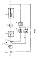
- FIG. 1 shows a control circuit 1 for a hydraulic drive 5 according to a first embodiment.
- the hydraulic drive 5 has a valve and a cylinder controlled by this valve.
- the control circuit 1 has a first comparator 10, a first multiplier 2, a first adder 11, a first functional element 3, a second multiplier 4, a first differentiator 7, a second differentiator 8 and a third multiplier 6.
- the control circuit 1 receives as input a signal x r indicative of the target position of the cylinder.
- the input signal x r is switched to a first input of the first comparator 10, which receives at its second input the signal x, which indicates the current position of the cylinder.
- the output signal of the first comparator 10 is received by the first multiplier 2, which multiplies this by the value ⁇ 1 .
- the signal x is also fed to the input of the first differentiator 7, which derives the signal x and generates therefrom the signal x. This signal is given to the input of the second differentiator 8, which thus outputs the signal x.
- the signal x in the third multiplier 6 is multiplied by the value ⁇ 2 .
- the output signals of the first multiplier 2, the third multiplier 6 and the second differentiator 8 are fed to the inputs of the adder 11, which adds these input signals and outputs as the sum the signal s.
- the function formed by the signal s is also referred to as a switching function.
- the first functional element 3 shares this Signal s by a constant F and uses the result of this division as an argument for a sat function.
- the function result of the sat function which the function block 3 outputs at its output, is multiplied by the value -K in the second multiplier, where K is a constant> 0, and the result of this multiplication is applied as voltage u to the valve of the Drive 5 output.
- the valve-controlled drive 5 includes a continuous valve and a cylinder.
- the cylinder contains a piston whose position is measured as a distance and output as signal x.
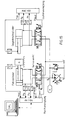
- FIG. 2 shows details of the electric drive 5 FIG. 1 ,
- the drive unit 5 includes a differential cylinder 14 with built-way sensor 24, a sensor electronics 16, a control valve 17 and an electronic unit 18.
- the differential cylinder 14 has a piston 19, the cylinder space of the differential cylinder 14 in a piston rod side pressure chamber 21 and divided into a piston-side pressure chamber 22.
- the Weggeber24 takes with the help of the measuring tube 23, the position of the piston, which is converted by the sensor electronics 16 into the electrical signal x.
- the control valve 17 is driven by the electronics 18.
- the control valve 17 has a pressure port P, which is controlled by a pump 42, and a tank port T, which is connected to the tank 44, and two outputs A and B on.
- the output A is connected to the pressure chamber 22 and the output B to the pressure chamber 21.
- the differential cylinder 14 is used for a continuous casting plant. With the help of the piston rod 20 a strand is pulled. During the casting process, often the speed of the piston movement and the direction of the piston rod movement are changed. In addition, since the mass of the load changes in the course of the casting process, the control with conventional control mechanisms is difficult.
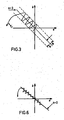
- FIG. 3 illustrates a switching line in the phase plane.
- the phase plane is spanned by the difference function e and the derivative of this difference function e.
- the sliding mode controller is a state controller with position, speed and acceleration feedback.
- the equations (8) and (9) represent an important approach to a first determination of the two parameters. Furthermore, the choice of the sampling time has a significant influence on the control behavior and should not be more than 1 ms in the selected embodiment.
- the control circuit off FIG. 1 was stimulated with the simulation program Matlab / Simulink using a 6th order nonlinear path model and also with a simulation program called MOSIHS.
- the simulation results for an exemplarily selected cylinder / valve combination show a very good control behavior in positioning processes as well as trajectory tracking. In particular, shorter settling times and lower follow-up distances result. It is also a greater robustness to recognize fluctuations in parameters such as mass and friction.
- FIG. 4 shows a second embodiment of the control circuit.
- the control circuit 30 is configured to control the hydraulic drive 36 and includes a first comparator 31, a first multiplier 32, an adder 33, a first functional block 34, a second multiplier 35, a first differentiator 37, a second differentiator 39, a third differentiator 42 and a fourth differentiator 43.
- the Regelüngsscrien a second comparator 40, a third comparator 41 and a third multiplier 38.
- the first comparator 31 subtracts the signal x from the signal x r to the signal e.
- the signal x r is differentiated with the first differentiator 37 to the signal ⁇ r , whereupon this signal ⁇ r is differentiated by the second differentiator 39 to the signal ⁇ r after the time.
- the fourth differentiator 43 derives the signal x to the signal ⁇ , which in turn is derived by means of the third differentiator 42 to the signal ⁇ .
- the second comparator 40 generates the signal ⁇ by subtracting the signal ⁇ from the signal ⁇ .
- the signal e is multiplied by the multiplier 38 with the value - ⁇ 2
- the signal e is from the first multiplier 32 is multiplied by the constant value - ⁇ 1 .
- the adder 33 adds the output of the first multiplier 32, that of the third multiplier 38, and subtracts the output of the third comparator 41 from the resulting sum.
- the adder 33 outputs the signal s, which in the function block 34 corresponding to the function block 3 from FIG. 1 is used as an argument.
- the output signal of the first function block 34 is multiplied by the multiplier 35 with the value -K and the result of this multiplication output as the voltage u for controlling the drive 36.
- control is performed without the assumption that the derivative and the second derivative of the signal x r are zero.
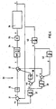
- FIG. 5 shows a device with a hydraulic drive 57 and a control circuit for this hydraulic drive 57 in a third embodiment.
- the hydraulic drive 57 in contrast to the embodiment of FIG. 1 a switching valve and not a continuous valve.
- the control device comprises a first comparator 51 which, by subtracting the signal x from the signal x r, forms the difference signal e which is multiplied in a first multiplier 52 by the factor - ⁇ 1 .
- the signal x r is derived in a first differentiator 58 to the signal ⁇ r , which in turn is derived in the second differentiator 60 to the signal ⁇ r .
- a fourth differentiator 63 derives the signal x to the signal ⁇ , which in turn is derived to the signal ⁇ in a third differentiator 62 becomes.
- a second comparator 64 subtracts the signal ⁇ from the signal ⁇ r , whereby the signal ⁇ is formed, which is multiplied in the second multiplier 59 with the signal - ⁇ 2 .
- the signal ⁇ is formed by subtracting the signal ⁇ from the signal, ⁇ r .
- a third multiplier 61 the signal ⁇ is multiplied by the value - ⁇ 3 .
- the adder 53 subtracts the output of the third multiplier 61 from the sum of the outputs of the multipliers 52 and 59.
- the output of the adder 53 is the signal s used as the input to the dead zone 54.
- the output signal of the dead-zone element 54 serves as an argument of the function block 55.
- the output signal of the function block 55 is multiplied in a fourth multiplier 56 by the value -K to the signal u.
- the signal u is the drive signal for the hydraulic drive 57.
- control circuit results as follows.
- K the maximum valve voltage, e.g. 10 V.
- the so-called “chattering” is avoided by using the dead zone.
- FIG. 6 illustrates a switching line s in the phase plane for the embodiment according to FIG. 5 , Compared to FIG. 2 It can be seen that the curve that marks the chattering has break points.
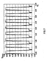
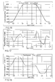
- FIG. 7 shows the speed control for a pull cylinder in a continuous casting with a sliding mode control according to the invention.
- a pull cylinder of the drive 5 As a pull cylinder of the drive 5, a synchronous cylinder is used.
- the assumed traction is 70kN. Due to different strand diameters and strand lengths, different mass ratios result from a minimum of 5400 kg to a maximum of 31800 kg. Furthermore, different stiffnesses arise in the strand, so that the control is additionally difficult.
- the desired speed and the actual speed of the strand are plotted in millimeters per second over time in seconds.
- the strand has a diameter of 120 mm and the minimum diameter of 5406 kg.
- the desired speed changes regularly between 90 mm / s and -10 mm / s.
- the actual speed follows the course, in the usual uniform.
- FIG. 8 shows in comparison to the speed control for a pull cylinder with a conventional control.
- a controller with a P-control, p-point feedback and setpoint induction was created to obtain good control characteristics.
- the regulator was loaded with the same load as in FIG. 7 operated. It turns out that vibrations occur in the scheme after FIG. 7 did not occur.
- the simulations were carried out for different strand diameters and masses. It turned out that the sliding-mode control provided better results especially for large masses and is thus much more robust.
- FIG. 14 shows such a control structure that is used only during the adjustment process. Then the complete SMC controller is used again.
- FIG. 14 represents only a schematic diagram, the actual hardware implementation may vary depending on the control unit.
- the test structure 140 consists of 3 components: an SM controller, a state controller, and a pulse switch.
- the two regulators are operated in a fixed-value control mode in which x SOLL-SMC and x REF ZSR are each constant.
- the SCM controller receives the values Xist and Xsoll as well as the first and second derivative of Xist.
- the switching function is determined according to Equation 4.
- the discontinuous portion can be set by the operator to hard or soft switching (sgn / sat function).
- the discontinuous fraction and the equivalent fraction are added to the output voltage U SMC of the SMC regulator.
- the pulse generator switches the output voltage U SMC of the SMC controller or the output voltage U ZSR of the state controller to its output.
- the pulse switch connects the output U Vent valve voltage to the state controller and thus the drive is set to the position x REF ZSR .
- a pulse with a defined width T is generated, this Implus switches the valve voltage to the SMC output.
- the cylinder is controlled to position x SOLL-SMC , whereby at the end of the pulse, the SMC controller automatically switches back to the state control loop.
- FIG. 15 represents the cylinder position and the switching process of the control circuits.
- the adjustment of the corresponding pulse width allows the accurate examination of the convergence and chattering phase, whereas the chattering phase is less limited to the switching of the valve. With this method the danger of resonance was eliminated.
- k ' the smaller the chattering amplitudes. This allows F max to be chosen for better dynamic behavior.
- the selected k 'must be big enough to guarantee stability.
- the moving mass can be changed from 650 to 1650kg.
- An incremental displacement transducer with a resolution of 1 ⁇ m was used to record the position of the driving cylinder.
- the counterforce (as a disturbance variable) was specified by a load pressure-controlled counterforce cylinder.
- the drag cylinder was controlled independently of the driving cylinder with a HNC100 card.
- the sliding-mode controller is particularly suitable for tasks in which a certain setpoint profile containing the setpoint position, setpoint speed and setpoint acceleration must be followed. For example, plastic injection molding machines or machine tools are moved over defined profiles.
- the measurements carried out show, as expected, a stable, "chattering-free" behavior. The wake of the given trajectory is very good throughout the stroke.
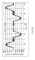
- FIG. 17 shows the setpoint and actual position
- FIG. 18 shows the positioning accuracy
- FIG. 18 the target and actual speed
- FIG. 20 the nominal and actual acceleration of the cylinder position.
- Figures 21 and 22 show the speed characteristics for the slide masses 650 kg and 1650 kg.
Landscapes
- Engineering & Computer Science (AREA)
- Health & Medical Sciences (AREA)
- Artificial Intelligence (AREA)
- Computer Vision & Pattern Recognition (AREA)
- Evolutionary Computation (AREA)
- Medical Informatics (AREA)
- Software Systems (AREA)
- Physics & Mathematics (AREA)
- General Physics & Mathematics (AREA)
- Automation & Control Theory (AREA)
- Feedback Control In General (AREA)
Applications Claiming Priority (1)
| Application Number | Priority Date | Filing Date | Title |
|---|---|---|---|
| DE102008048001 | 2008-09-19 |
Publications (2)
| Publication Number | Publication Date |
|---|---|
| EP2169482A2 true EP2169482A2 (fr) | 2010-03-31 |
| EP2169482A3 EP2169482A3 (fr) | 2010-12-08 |
Family
ID=41560373
Family Applications (1)
| Application Number | Title | Priority Date | Filing Date |
|---|---|---|---|
| EP09011542A Withdrawn EP2169482A3 (fr) | 2008-09-19 | 2009-09-09 | Dispositif et procédé de réglage d'un entraînement hydraulique avec un régulateur Sliding Mode |
Country Status (2)
| Country | Link |
|---|---|
| EP (1) | EP2169482A3 (fr) |
| DE (1) | DE102009040672A1 (fr) |
Cited By (2)
| Publication number | Priority date | Publication date | Assignee | Title |
|---|---|---|---|---|
| CN118795771A (zh) * | 2024-06-17 | 2024-10-18 | 苏州科技大学 | 一种电液系统自适应抗扰降阶控制方法 |
| CN119861563A (zh) * | 2024-12-27 | 2025-04-22 | 浙江工业大学 | 一种兼顾比例阀高动态低滞环和微动特性的非线性颤振控制方法 |
Families Citing this family (1)
| Publication number | Priority date | Publication date | Assignee | Title |
|---|---|---|---|---|
| DE102015210698A1 (de) * | 2015-06-11 | 2016-12-15 | Zf Friedrichshafen Ag | Ansteuerung von Schaltklauen |
Citations (1)
| Publication number | Priority date | Publication date | Assignee | Title |
|---|---|---|---|---|
| US7231265B2 (en) | 2002-01-23 | 2007-06-12 | Honda Giken Kogyo Kabushiki Kaisha | Control system for plant |
-
2009
- 2009-09-09 DE DE102009040672A patent/DE102009040672A1/de not_active Withdrawn
- 2009-09-09 EP EP09011542A patent/EP2169482A3/fr not_active Withdrawn
Patent Citations (1)
| Publication number | Priority date | Publication date | Assignee | Title |
|---|---|---|---|---|
| US7231265B2 (en) | 2002-01-23 | 2007-06-12 | Honda Giken Kogyo Kabushiki Kaisha | Control system for plant |
Cited By (2)
| Publication number | Priority date | Publication date | Assignee | Title |
|---|---|---|---|---|
| CN118795771A (zh) * | 2024-06-17 | 2024-10-18 | 苏州科技大学 | 一种电液系统自适应抗扰降阶控制方法 |
| CN119861563A (zh) * | 2024-12-27 | 2025-04-22 | 浙江工业大学 | 一种兼顾比例阀高动态低滞环和微动特性的非线性颤振控制方法 |
Also Published As
| Publication number | Publication date |
|---|---|
| EP2169482A3 (fr) | 2010-12-08 |
| DE102009040672A1 (de) | 2010-03-25 |
Similar Documents
| Publication | Publication Date | Title |
|---|---|---|
| DE102019208698B4 (de) | Zwischenfahrzeugabstand-Steuervorrichtung | |
| DE102006045820B4 (de) | Verfahren und Vorrichtung zur automatischen Einstellung eines Motorreglers | |
| DE102005059530B4 (de) | Befehlsgenerierungsvorrichtung | |
| DE102012106771A1 (de) | Controller für elektromotor, umfassend eine funktion zum simultanen schätzen von trägheit, reibung und federkonstante | |
| DE102019002644A1 (de) | Steuerung und Steuerverfahren | |
| DE112004001083B4 (de) | Positionssteuerung und Steuerverfahren dafür | |
| DE4342057B4 (de) | Verfahren zur Adaption der Regelparameter einer elektrohydraulischen Achse | |
| DE102017213650A1 (de) | Verfahren zum Regeln eines hydraulischen Systems, Regeleinheit für ein hydraulisches System und hydraulisches System | |
| EP1915650B1 (fr) | Procede de regulation et regulateur destines a un systeme mecanique/hydraulique | |
| EP0896263A2 (fr) | Procédé et circuit pour determiner les parametres optimaux pour contrÔle de vitasse de rotation | |
| EP0308762B1 (fr) | Dispositif de régulation de la position d'un mécanisme d'avancement hydraulique, notamment d'une estampe ou presse hydraulique | |
| DE102011016559A1 (de) | Verfahren zum Durchführen adaptiver Reibungskompensation in einem Aktuator, das eine mit einer Temperaturänderung verbundene Variation der Reibungseigenschaften eines Wellgetriebes berücksichtigt | |
| EP2169482A2 (fr) | Dispositif et procédé de réglage d'un entraînement hydraulique avec un régulateur Sliding Mode | |
| DE69401590T2 (de) | Algorithmus zur erzeugung einer reibung für eine aktive handsteuerung | |
| DE102020213262A1 (de) | Verfahren zum Betreiben eines hydraulischen Antriebs | |
| EP1279851B1 (fr) | Méthode de commande d'un embrayage automatique de véhicule | |
| EP1005147B1 (fr) | Méthode et circuit électrique pour déterminer le gain optimal de l'intégrateur d'un régulateur de vitesse | |
| WO2009156022A1 (fr) | Système de commande comprenant une soupape de limitation de pression | |
| DE102016214708A1 (de) | Stetigventileinheit, hydraulische Achse und Verfahren zum Betreiben einer hydraulischen Achse | |
| DE102022206535A1 (de) | Verfahren zur Regelung von hydraulischen Komponenten | |
| EP4524400B1 (fr) | Procede et dispositif de commande d'un dispositif de production d'ecoulement | |
| EP0775337A1 (fr) | Systeme de regulation de mecanismes hydrauliques d'entrainement | |
| EP4299904B1 (fr) | Procédé de régulation de pompes à fluide à vitesse variable | |
| DE602006000731T2 (de) | Autoadaptives Einstellungsgerät zur Positionssteuerung von Aktuatoren in einem Antriebssystem mittels Gleitmodusverfahren und entsprechendes Betriebsverfahren | |
| EP2199879A1 (fr) | Dispositif et procédé de minimisation d'une erreur de suivi dynamique |
Legal Events
| Date | Code | Title | Description |
|---|---|---|---|
| PUAI | Public reference made under article 153(3) epc to a published international application that has entered the european phase |
Free format text: ORIGINAL CODE: 0009012 |
|
| AK | Designated contracting states |
Kind code of ref document: A2 Designated state(s): AT BE BG CH CY CZ DE DK EE ES FI FR GB GR HR HU IE IS IT LI LT LU LV MC MK MT NL NO PL PT RO SE SI SK SM TR |
|
| AX | Request for extension of the european patent |
Extension state: AL BA RS |
|
| PUAL | Search report despatched |
Free format text: ORIGINAL CODE: 0009013 |
|
| AK | Designated contracting states |
Kind code of ref document: A3 Designated state(s): AT BE BG CH CY CZ DE DK EE ES FI FR GB GR HR HU IE IS IT LI LT LU LV MC MK MT NL NO PL PT RO SE SI SK SM TR |
|
| AX | Request for extension of the european patent |
Extension state: AL BA RS |
|
| RIC1 | Information provided on ipc code assigned before grant |
Ipc: F02D 41/14 20060101ALI20101102BHEP Ipc: G05B 19/19 20060101ALI20101102BHEP Ipc: G05B 13/04 20060101ALI20101102BHEP Ipc: G05B 11/00 20060101AFI20100223BHEP |
|
| 17P | Request for examination filed |
Effective date: 20110608 |
|
| STAA | Information on the status of an ep patent application or granted ep patent |
Free format text: STATUS: THE APPLICATION IS DEEMED TO BE WITHDRAWN |
|
| 18D | Application deemed to be withdrawn |
Effective date: 20110609 |