EP2169689B1 - R-fe-b-seltenerdgesinterter magnet und herstellungsverfahren dafür - Google Patents
R-fe-b-seltenerdgesinterter magnet und herstellungsverfahren dafür Download PDFInfo
- Publication number
- EP2169689B1 EP2169689B1 EP08790126.0A EP08790126A EP2169689B1 EP 2169689 B1 EP2169689 B1 EP 2169689B1 EP 08790126 A EP08790126 A EP 08790126A EP 2169689 B1 EP2169689 B1 EP 2169689B1
- Authority
- EP
- European Patent Office
- Prior art keywords
- sintered magnet
- magnet body
- rare
- earth sintered
- based rare
- Prior art date
- Legal status (The legal status is an assumption and is not a legal conclusion. Google has not performed a legal analysis and makes no representation as to the accuracy of the status listed.)
- Active
Links
Images



Classifications
-
- H—ELECTRICITY
- H01—ELECTRIC ELEMENTS
- H01F—MAGNETS; INDUCTANCES; TRANSFORMERS; SELECTION OF MATERIALS FOR THEIR MAGNETIC PROPERTIES
- H01F1/00—Magnets or magnetic bodies characterised by the magnetic materials therefor; Selection of materials for their magnetic properties
- H01F1/01—Magnets or magnetic bodies characterised by the magnetic materials therefor; Selection of materials for their magnetic properties of inorganic materials
- H01F1/03—Magnets or magnetic bodies characterised by the magnetic materials therefor; Selection of materials for their magnetic properties of inorganic materials characterised by their coercivity
- H01F1/032—Magnets or magnetic bodies characterised by the magnetic materials therefor; Selection of materials for their magnetic properties of inorganic materials characterised by their coercivity of hard-magnetic materials
- H01F1/04—Magnets or magnetic bodies characterised by the magnetic materials therefor; Selection of materials for their magnetic properties of inorganic materials characterised by their coercivity of hard-magnetic materials metals or alloys
- H01F1/047—Alloys characterised by their composition
- H01F1/053—Alloys characterised by their composition containing rare earth metals
-
- C—CHEMISTRY; METALLURGY
- C22—METALLURGY; FERROUS OR NON-FERROUS ALLOYS; TREATMENT OF ALLOYS OR NON-FERROUS METALS
- C22C—ALLOYS
- C22C38/00—Ferrous alloys, e.g. steel alloys
- C22C38/005—Ferrous alloys, e.g. steel alloys containing rare earths, i.e. Sc, Y, Lanthanides
-
- B—PERFORMING OPERATIONS; TRANSPORTING
- B22—CASTING; POWDER METALLURGY
- B22F—WORKING METALLIC POWDER; MANUFACTURE OF ARTICLES FROM METALLIC POWDER; MAKING METALLIC POWDER; APPARATUS OR DEVICES SPECIALLY ADAPTED FOR METALLIC POWDER
- B22F3/00—Manufacture of workpieces or articles from metallic powder characterised by the manner of compacting or sintering; Apparatus specially adapted therefor ; Presses and furnaces
- B22F3/24—After-treatment of workpieces or articles
-
- C—CHEMISTRY; METALLURGY
- C22—METALLURGY; FERROUS OR NON-FERROUS ALLOYS; TREATMENT OF ALLOYS OR NON-FERROUS METALS
- C22C—ALLOYS
- C22C33/00—Making ferrous alloys
- C22C33/02—Making ferrous alloys by powder metallurgy
- C22C33/0257—Making ferrous alloys by powder metallurgy characterised by the range of the alloying elements
- C22C33/0278—Making ferrous alloys by powder metallurgy characterised by the range of the alloying elements with at least one alloying element having a minimum content above 5%
-
- H—ELECTRICITY
- H01—ELECTRIC ELEMENTS
- H01F—MAGNETS; INDUCTANCES; TRANSFORMERS; SELECTION OF MATERIALS FOR THEIR MAGNETIC PROPERTIES
- H01F1/00—Magnets or magnetic bodies characterised by the magnetic materials therefor; Selection of materials for their magnetic properties
- H01F1/01—Magnets or magnetic bodies characterised by the magnetic materials therefor; Selection of materials for their magnetic properties of inorganic materials
- H01F1/03—Magnets or magnetic bodies characterised by the magnetic materials therefor; Selection of materials for their magnetic properties of inorganic materials characterised by their coercivity
- H01F1/032—Magnets or magnetic bodies characterised by the magnetic materials therefor; Selection of materials for their magnetic properties of inorganic materials characterised by their coercivity of hard-magnetic materials
- H01F1/04—Magnets or magnetic bodies characterised by the magnetic materials therefor; Selection of materials for their magnetic properties of inorganic materials characterised by their coercivity of hard-magnetic materials metals or alloys
- H01F1/047—Alloys characterised by their composition
- H01F1/053—Alloys characterised by their composition containing rare earth metals
- H01F1/055—Alloys characterised by their composition containing rare earth metals and magnetic transition metals, e.g. SmCo5
- H01F1/057—Alloys characterised by their composition containing rare earth metals and magnetic transition metals, e.g. SmCo5 and IIIa elements, e.g. Nd2Fe14B
- H01F1/0571—Alloys characterised by their composition containing rare earth metals and magnetic transition metals, e.g. SmCo5 and IIIa elements, e.g. Nd2Fe14B in the form of particles, e.g. rapid quenched powders or ribbon flakes
- H01F1/0575—Alloys characterised by their composition containing rare earth metals and magnetic transition metals, e.g. SmCo5 and IIIa elements, e.g. Nd2Fe14B in the form of particles, e.g. rapid quenched powders or ribbon flakes pressed, sintered or bonded together
- H01F1/0577—Alloys characterised by their composition containing rare earth metals and magnetic transition metals, e.g. SmCo5 and IIIa elements, e.g. Nd2Fe14B in the form of particles, e.g. rapid quenched powders or ribbon flakes pressed, sintered or bonded together sintered
-
- H—ELECTRICITY
- H01—ELECTRIC ELEMENTS
- H01F—MAGNETS; INDUCTANCES; TRANSFORMERS; SELECTION OF MATERIALS FOR THEIR MAGNETIC PROPERTIES
- H01F1/00—Magnets or magnetic bodies characterised by the magnetic materials therefor; Selection of materials for their magnetic properties
- H01F1/01—Magnets or magnetic bodies characterised by the magnetic materials therefor; Selection of materials for their magnetic properties of inorganic materials
- H01F1/03—Magnets or magnetic bodies characterised by the magnetic materials therefor; Selection of materials for their magnetic properties of inorganic materials characterised by their coercivity
- H01F1/032—Magnets or magnetic bodies characterised by the magnetic materials therefor; Selection of materials for their magnetic properties of inorganic materials characterised by their coercivity of hard-magnetic materials
- H01F1/04—Magnets or magnetic bodies characterised by the magnetic materials therefor; Selection of materials for their magnetic properties of inorganic materials characterised by their coercivity of hard-magnetic materials metals or alloys
- H01F1/06—Magnets or magnetic bodies characterised by the magnetic materials therefor; Selection of materials for their magnetic properties of inorganic materials characterised by their coercivity of hard-magnetic materials metals or alloys in the form of particles, e.g. powder
- H01F1/08—Magnets or magnetic bodies characterised by the magnetic materials therefor; Selection of materials for their magnetic properties of inorganic materials characterised by their coercivity of hard-magnetic materials metals or alloys in the form of particles, e.g. powder pressed, sintered, or bound together
-
- H—ELECTRICITY
- H01—ELECTRIC ELEMENTS
- H01F—MAGNETS; INDUCTANCES; TRANSFORMERS; SELECTION OF MATERIALS FOR THEIR MAGNETIC PROPERTIES
- H01F41/00—Apparatus or processes specially adapted for manufacturing or assembling magnets, inductances or transformers; Apparatus or processes specially adapted for manufacturing materials characterised by their magnetic properties
- H01F41/02—Apparatus or processes specially adapted for manufacturing or assembling magnets, inductances or transformers; Apparatus or processes specially adapted for manufacturing materials characterised by their magnetic properties for manufacturing cores, coils, or magnets
-
- H—ELECTRICITY
- H01—ELECTRIC ELEMENTS
- H01F—MAGNETS; INDUCTANCES; TRANSFORMERS; SELECTION OF MATERIALS FOR THEIR MAGNETIC PROPERTIES
- H01F41/00—Apparatus or processes specially adapted for manufacturing or assembling magnets, inductances or transformers; Apparatus or processes specially adapted for manufacturing materials characterised by their magnetic properties
- H01F41/02—Apparatus or processes specially adapted for manufacturing or assembling magnets, inductances or transformers; Apparatus or processes specially adapted for manufacturing materials characterised by their magnetic properties for manufacturing cores, coils, or magnets
- H01F41/0253—Apparatus or processes specially adapted for manufacturing or assembling magnets, inductances or transformers; Apparatus or processes specially adapted for manufacturing materials characterised by their magnetic properties for manufacturing cores, coils, or magnets for manufacturing permanent magnets
- H01F41/0293—Apparatus or processes specially adapted for manufacturing or assembling magnets, inductances or transformers; Apparatus or processes specially adapted for manufacturing materials characterised by their magnetic properties for manufacturing cores, coils, or magnets for manufacturing permanent magnets diffusion of rare earth elements, e.g. Tb, Dy or Ho, into permanent magnets
-
- B—PERFORMING OPERATIONS; TRANSPORTING
- B22—CASTING; POWDER METALLURGY
- B22F—WORKING METALLIC POWDER; MANUFACTURE OF ARTICLES FROM METALLIC POWDER; MAKING METALLIC POWDER; APPARATUS OR DEVICES SPECIALLY ADAPTED FOR METALLIC POWDER
- B22F3/00—Manufacture of workpieces or articles from metallic powder characterised by the manner of compacting or sintering; Apparatus specially adapted therefor ; Presses and furnaces
- B22F3/24—After-treatment of workpieces or articles
- B22F2003/248—Thermal after-treatment
-
- B—PERFORMING OPERATIONS; TRANSPORTING
- B22—CASTING; POWDER METALLURGY
- B22F—WORKING METALLIC POWDER; MANUFACTURE OF ARTICLES FROM METALLIC POWDER; MAKING METALLIC POWDER; APPARATUS OR DEVICES SPECIALLY ADAPTED FOR METALLIC POWDER
- B22F2999/00—Aspects linked to processes or compositions used in powder metallurgy
-
- C—CHEMISTRY; METALLURGY
- C22—METALLURGY; FERROUS OR NON-FERROUS ALLOYS; TREATMENT OF ALLOYS OR NON-FERROUS METALS
- C22C—ALLOYS
- C22C2202/00—Physical properties
- C22C2202/02—Magnetic
Definitions
- the present invention relates to an R-Fe-B based rare-earth sintered magnet including crystal grains of an R 2 Fe 14 B type compound (where R is a rare-earth element) as a main phase and a method for producing such a magnet. More particularly, the present invention relates to an R-Fe-B based rare-earth sintered magnet, which includes a light rare-earth element RL (which is at least one of Nd and Pr) as a major rare-earth element R and in which a portion of the light rare-earth element RL is replaced with a heavy rare-earth element RH (which is at least one element selected from the group consisting of Dy, Ho and Tb) and a method for producing such a magnet.
- a light rare-earth element RL which is at least one of Nd and Pr
- RH which is at least one element selected from the group consisting of Dy, Ho and Tb
- An R-Fe-B based rare-earth sintered magnet including an Nd 2 Fe 14 B type compound phase as a main phase, is known as a permanent magnet with the highest performance, and has been used in various types of motors such as a voice coil motor (VCM) for a hard disk drive and a motor for a hybrid car and in numerous types of consumer electronic appliances.
- VCM voice coil motor
- the R-Fe-B based rare-earth sintered magnet should exhibit thermal resistance that is high enough to withstand an operating environment at an elevated temperature.
- the thermal resistance of an R-Fe-B based rare-earth sintered magnet can be increased by raising its coercivity.
- a molten alloy including a heavy rare-earth element RH as an additional element, may be used.
- the light rare-earth element RL which is included as a rare-earth element R in an R 2 Fe 14 B phase, is replaced with a heavy rare-earth element RH, and therefore, the magnetocrystalline anisotropy (which is a decisive quality parameter that determines the coercivity) of the R 2 Fe 14 B phase improves.
- the magnetic moment of the light rare-earth element RL in the R 2 Fe 14 B phase has the same direction as that of Fe
- the magnetic moments of the heavy rare-earth element RH and Fe have mutually opposite directions. That is why the remanence B r would decrease in proportion to the percentage of the light rare-earth element RL replaced with the heavy rare-earth element RH.
- the heavy rare-earth element RH is one of rare natural resources, its use is preferably cut down as much as possible. For these reasons, the method in which the light rare-earth element RL is entirely replaced with the heavy rare-earth element RH is not preferred.
- the heavy rare-earth element RH is distributed a lot in the vicinity of the grain boundary of the R 2 Fe 14 B phase, and therefore, the magnetocrystalline anisotropy of the R 2 Fe 14 B phase can be improved efficiently in the outer periphery (surface region) of the main phase grain.
- the R-Fe-B based rare-earth sintered magnet has a nucleation-type coercivity generating mechanism. That is why if a lot of the heavy rare-earth element RH is distributed in the outer periphery of the main phase (i.e., near the grain boundary thereof), the magnetocrystalline anisotropy of the entire crystal grain is improved, the nucleation of reverse magnetic domains can be interfered with, and the coercivity increases as a result. At the core of the crystal grains, no light rare-earth element RL is replaced with the heavy rare-earth element RH. Consequently, the decrease in remanence B r can be minimized there, too.
- the heavy rare-earth element RH has an increased diffusion rate during the sintering process (which is carried out at a temperature of 1,000 °C to 1,200 °C on an industrial scale) and could diffuse to reach the core of the crystal grains, too. For that reason, it is not easy to obtain the expected crystal structure.
- Patent Document No. 1 teaches forming a thin-film layer, including R' that is at least one element selected from the group consisting of Nd, Pr, Dy, Ho and Tb on the surface of a sintered magnet body to be machined and then subjecting it to a heat treatment within either a vacuum or an inert atmosphere, thereby turning a deformed layer on the machined surface into a repaired layer through a diffusion reaction between the thin-film layer and the deformed layer and recovering the coercivity.
- R' that is at least one element selected from the group consisting of Nd, Pr, Dy, Ho and Tb
- Patent Document No. 2 discloses that a metallic element R (which is at least one rare-earth element selected from the group consisting of Y, Nd, Dy, Pr, Ho and Tb) is diffused to a depth that is at least equal to the radius of crystal grains exposed on the uppermost surface of a small-sized magnet while the thin film is being deposited, thereby repairing the damage done on the machined surface and increasing (BH) max .
- R which is at least one rare-earth element selected from the group consisting of Y, Nd, Dy, Pr, Ho and Tb
- Patent Document No. 3 teaches providing a layer that has higher intrinsic coercivity than the core of the magnet body in the vicinity of the surface of a sintered magnet.
- a layer with high intrinsic coercivity may be formed by depositing a thin-film layer made of a material such as Tb, Dy, Al or Ga on the surface of a sintered magnet by sputtering, for example, and then diffusing that material into a surface region of the sintered magnet through a heat treatment.
- Patent Document No. 4 discloses that a film including an element that is selected from the group consisting of Pr, Dy, Tb and Ho is deposited on the surface of an R-Fe-B based magnet by some physical method and then made to diffuse and permeate, thereby achieving high coercivity or high remanence.
- Patent Document No. 5 discloses that by depositing a CVD film, consisting mostly of a rare-earth element, on the surface of a magnet with a thickness of 2 mm or less and then subjecting it to a heat treatment, the rare-earth element would diffuse inside the magnet, the machined and damaged layer in the vicinity of the surface could be repaired, and eventually the magnetic properties could be recovered.
- a CVD film consisting mostly of a rare-earth element
- Patent Document No. 6 discloses a method of sorbing a rare-earth element to recover the coercivity of a very small R-Fe-B based sintered magnet or its powder. According to the method of Patent Document No. 6, a sorption metal, which is a rare-earth metal such as Yb, Eu or Sm with a relatively low boiling point, and a very small R-Fe-B based sintered magnet or its powder are mixed together, and then the mixture is subjected to a heat treatment to heat it uniformly in a vacuum while stirring it up. As a result of this heat treatment, the rare-earth metal is not only deposited on the surface of the magnet but also diffused inward.
- Patent Document No. 6 also discloses an embodiment in which a rare-earth metal with a high boiling point such as Dy is sorbed.
- Dy is selectively heated to a high temperature by an induction heating process.
- Dy has a boiling point of 2,560 °C.
- Yb with a boiling point of 1,193 °C should be heated to a temperature of 800 °C to 850 °C but could not be heated sufficiently by normal resistance heating process.
- the Dy be heated to a temperature exceeding 1,000 °C to say the least.
- Patent Document No. 6 also discloses that the temperature of the very small R-Fe-B based sintered magnet and its powder is preferably maintained within the range of 700 °C to 850 °C.
- a sintered magnet body has its surface coated with a film of rare-earth metal and then subjected to a heat treatment, thereby diffusing the rare-earth metal inside the magnet. That is why in the surface region of the magnet (with a thickness of several tens of ⁇ m as measured from the surface), a big difference in rare-earth metal concentration at the interface between the rare-earth metal film deposited and the sintered magnet body should inevitably generate a driving force to diffuse the rare-earth metal into the main phase as well. Consequently, the remanence B r drops.
- the sorption material and the magnet are both heated by induction heating process. That is why it is not easy to heat only the rare-earth metal to a sufficiently high temperature and yet maintain the magnet at a temperature that is low enough to avoid affecting the magnetic properties. As a result, the magnet will often have a powder state or a very small size and is not easily subjected to the induction heating process in either case.
- the rare-earth metal is also deposited a lot on unexpected portions of the deposition system (e.g., on the inner walls of the vacuum chamber) other than the magnet during the deposition process, which is against the policy of saving a heavy rare-earth element that is one of rare and valuable natural resources.
- the heavy rare-earth element RH has hardly caused intragrain diffusion (i.e., volume diffusion) into main phase crystal grains) but is distributed only in the outer periphery (i.e., in the vicinity of the grain boundary) and of which the coercivity has been increased deeper inside almost without decreasing the remanence.
- An R-Fe-B based rare-earth sintered magnet according to the present invention includes an R-Fe-B based rare-earth sintered magnet body that includes, as a main phase, crystal grains of an R 2 Fe 14 B type compound, including a light rare-earth element RL (which is at least one of Nd and Pr) as a major rare-earth element R, and a heavy rare-earth element RH (which is at least one element selected from the group consisting of Dy, Ho and Tb).
- RL which is at least one of Nd and Pr
- RH which is at least one element selected from the group consisting of Dy, Ho and Tb
- the crystal grains of the R 2 Fe 14 B type compound have an RH diffused layer ((RL 1-x RH x ) 2 Fe 14 B (where 0.2 ⁇ x ⁇ 0.75) layer) with an average thickness of 2 ⁇ m or less in their outer periphery.
- the crystal grains of the R 2 Fe 14 B type compound have an RH diffused layer with an average thickness of 0.5 ⁇ m or less in their outer periphery.
- the R-Fe-B based rare-earth sintered magnet body has a size of 1 mm to 4 mm as measured in a thickness direction.
- a difference ⁇ H cJ 1 in coercivity between the entire R-Fe-B based rare-earth sintered magnet body and the rest of the R-Fe-B based rare-earth sintered magnet body, from which a surface portion has been removed by 200 ⁇ m as measured from its surface, is 150 kA/m or less.
- the R-Fe-B based rare-earth sintered magnet body has a size of more than 4 mm in the thickness direction.
- a difference ⁇ H cJ 2 in coercivity between the first and second layer portions is 300 kA/m or less.
- the RH diffused layer at the depth of 500 ⁇ m under the surface of the R-Fe-B based rare-earth sintered magnet body has the composition (RL 1-x RH x ) 2 Fe 14 B (where 0.2 ⁇ x ⁇ 0.75).
- the crystal grains of the R 2 Fe 14 B type compound in a region of the R-Fe-B based rare-earth sintered magnet body between the depths of 20 ⁇ m and 500 ⁇ m under its surface, the crystal grains of the R 2 Fe 14 B type compound have an RH diffused layer in their outer periphery. The greater the depth under the surface of the R-Fe-B based rare-earth sintered magnet body, the thinner the RH diffused layer gets in the outer periphery of the crystal grains of the R 2 Fe 14 B type compound.
- the (RL 1-x RH x ) 2 Fe 14 B layer has a uniform composition in which x has a dispersion of 10% or less at least within a single crystal grain.
- the thickness of the (RL 1-x RH x ) 2 Fe 14 B (where 0.2 ⁇ x ⁇ 0.75) layer in the crystal grains of the R 2 Fe 14 B type compound is 20% or less of the average grain size of the crystal grains of the R 2 Fe 14 B type compound.
- the concentration of RH in the (RL 1-x RH x ) 2 Fe 14 B (where 0.2 ⁇ x ⁇ 0.75) layer is at least 6.0 mass% greater than that of RH at the core of the crystal grains.
- the magnet has an RH-RL-O compound in at least one grain boundary triple junction, which is located at a depth of 100 ⁇ m or less under the surface of the R-Fe-B based rare-earth sintered magnet body.
- the concentration of RH in the (RL 1-x RH x ) 2 Fe 14 B (where 0.2 ⁇ x ⁇ 0.75) layer is smaller than that of the RH-RL-O compound of a grain boundary layer, which surrounds the crystal grain of the R 2 Fe 14 B type compound, but greater than that of the rest of the grain boundary layer other than the RH-RL-O compound.
- a method for producing an R-Fe-B based rare-earth sintered magnet according to the present invention includes the steps of: (a) providing an R-Fe-B based rare-earth sintered magnet body, which includes, as a main phase, crystal grains of an R 2 Fe 14 B type compound including a light rare-earth element RL (which is at least one of Nd and Pr) as a major rare-earth element R; (b) diffusing a heavy rare-earth element RH (which is at least one element selected from the group consisting of Dy, Ho and Tb) inside the R-Fe-B based rare-earth sintered magnet body; and (c) removing a surface portion of the R-Fe-B based rare-earth sintered magnet body, in which the heavy rare-earth element RH has been diffused, to a depth of 5 ⁇ m to 500 ⁇ m.
- the step (b) includes the steps of: (b1) arranging a bulk body including the heavy rare-earth element RH (which is at least one element selected from the group consisting of Dy, Ho and Tb), along with the R-Fe-B based rare-earth sintered magnet body, in a processing chamber; and (b2) heating the bulk body and the R-Fe-B based rare-earth sintered magnet body together to a temperature of 700 °C to 1,000 °C, thereby diffusing the heavy rare-earth element RH inside the R-Fe-B based rare-earth sintered magnet body while supplying the heavy rare-earth element RH from the bulk body onto the surface of the R-Fe-B based rare-earth sintered magnet body simultaneously.
- RH which is at least one element selected from the group consisting of Dy, Ho and Tb
- the step (b2) includes arranging the bulk body and the R-Fe-B based rare-earth sintered magnet body out of contact with each other in the processing chamber and leaving an average gap of 0.1 mm to 300 mm between them.
- the step (b2) includes setting a difference in temperature between the R-Fe-B based rare-earth sintered magnet body and the bulk body within 20 °C.
- the step (b2) includes adjusting the pressure of an atmospheric gas in the processing chamber within the range of 10 -5 Pa through 500 Pa.
- the step (b2) includes maintaining the temperatures of the bulk body and the R-Fe-B based rare-earth sintered magnet body within the range of 700 °C through 1,000 °C for 10 to 600 minutes.
- the method further includes, after the step (b2), the step (b3) of conducting a heat treatment at a temperature of 700 °C to 1,000 °C for 1 to 60 hours.
- the step (b3) is performed in the processing chamber in which the bulk body is arranged with the pressure of the atmospheric gas in the processing chamber adjusted to at least 500 Pa.
- the step (b3) is performed in either the processing chamber from which the bulk body has already been unloaded or in another processing chamber from which the bulk body is absent.
- a sintered magnet body which has had its coercivity H cJ increased, but its remanence B r decreased, by diffusing a heavy rare-earth element RH (which is at least one element selected from the group consisting of Dy, Ho and Tb) inside the sintered magnet body through the surface thereof by evaporation diffusion process (i.e., the process performed in the step (b)), has its portion near the surface (which will be sometimes referred to herein as a "surface portion") removed.
- RH which is at least one element selected from the group consisting of Dy, Ho and Tb
- the sintered magnet body of the present invention includes, as a main phase, crystal grains of an R 2 Fe 14 B type compound including a light rare-earth element RL (which is at least one of Nd and Pr) as a major rare-earth element R, the heavy rare-earth element RH that has been diffused inside the sintered magnet body through its surface by the evaporation diffusion process has reached the outer periphery of the crystal grains of the R 2 Fe 14 B type compound by way of the grain boundary phase (that is an R-rich phase) of the crystal grains of the R 2 Fe 14 B type compound.
- the grain boundary phase that is an R-rich phase
- the concentration of the heavy rare-earth element RH can be increased efficiently in the outer periphery of main phase crystal grains.
- the heavy rare-earth element RH tends to diffuse deeper inside, or reach closer to the core, of the crystal grains, compared to crystal grains of the R 2 Fe 14 B type compound that are located deeper than the surface portion. That is why in the surface portion of the sintered magnet body, the remanence B r will decrease more easily than deeper inside the sintered body.
- that surface portion of the sintered magnet body is removed after the diffusion.
- the heavy rare-earth element RH will diffuse and permeate deeper inside the sintered magnet body. That is why even if the surface portion of the magnet body was removed, the coercivity would hardly decrease compared to the magnet body that still has that surface portion.
- an R-Fe-B based sintered magnet body of which the coercivity H cJ has increased in a broader range (i.e., from the surface through the deeper region of the sintered magnet body) almost without decreasing the remanence B r compared to the sintered magnet body in which the heavy rare-earth element RH has not diffused yet, can be obtained.
- crystal grains of an R 2 Fe 14 B type compound have an (RL 1-x RH x ) 2 Fe 14 B (where 0.2 ⁇ x ⁇ 0.75) layer with an average thickness of 2 ⁇ m or less in their outer periphery.
- the light rare-earth element RL is at least one of Nd and Pr and the heavy rare-earth element RH is at least one element selected from the group consisting of Dy, Ho and Tb. If the mole fraction x were less than 0.2, the coercivity could not be increased as expected. Also, according to an evaporation diffusion process, it is difficult to diffuse RH and raise its concentration in the outer periphery of main phase crystal grains to the point that x exceeds 0.75.
- the "surface of the sintered magnet body” means the surface of the sintered magnet body, from which its surface portion has already been removed after the heavy rare-earth element RH has been introduced into the sintered magnet body from outside of the sintered magnet body, i.e., the machined surface (which may be a ground or polished surface). Therefore, if the "surface of the sintered magnet body” is covered with a coating of a metal or a resin, the “surface of the sintered magnet body” is not the surface of such a coating but the surface that is now covered with that coating.
- the crystal grains of the R 2 Fe 14 B type compound have an RH diffused layer with a thickness of 0.5 ⁇ m or less (which will also be referred to herein as a "layer with an increased RH concentration") in their outer periphery.
- An R-Fe-B based sintered magnet according to the present invention can be obtained by diffusing the heavy rare-earth element RH inward from the surface of an R-Fe-B based sintered magnet body by evaporation diffusion process and then removing a surface portion of the magnet body to a depth of 5 ⁇ m or more.
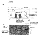
- FIG. 1(a) is a graph showing the results of a line analysis that was carried out on the crystal structure of an R-Fe-B based rare-earth sintered magnet according to the present invention at a depth of around 20 ⁇ m under its surface (from which the surface portion had already been removed) using an electron probe micro-analyzer (which will be abbreviated herein as an "EPMA").
- FIG. 1(b) is a schematic representation illustrating the crystal structure on which the line analysis was carried out. And the results shown in FIG.
- the "main phase” refers to crystal grains of an R 2 Fe 14 B type compound (where R is a rare-earth element)
- the “main phase Fe” represents the intensity of Fe in the crystal grains of the R 2 Fe 14 B type compound
- the “main phase Nd” represents the intensity of Nd in the crystal grains of the R 2 Fe 14 B type compound.
- the concentration of Nd decreased, but the concentration of Dy increased, compared to the main phase yet to be subjected to the diffusion process (which will be referred to herein as a "Dy diffused layer").
- the Dy diffused layer had a thickness of approximately 1 ⁇ m.
- this compound layer has the composition (RL 1-x RH x ) 2 Fe 14 B (where 0.2 ⁇ x ⁇ 0.75).
- the concentration of Dy at the core of the main phase agreed with the "Dy BG" level shown in FIG. 1(a) . That is to say, the concentration of Dy at the core of the main phase did not increase from the concentration of Dy in the main phase yet to be subjected to the diffusion process, and no Dy that had been introduced by diffusion from the surface of the magnet body was detected. Also, at the grain boundary triple junction (as indicated by the solid pentagon shown in FIG. 1(b) ) , there was an Nd-Dy oxide, which will be described in detail later.
- FIG. 2(a) is a transmission electron microscope (TEM) photograph representing the crystal structure of an R-Fe-B based rare-earth sintered magnet according to the present invention at a depth of approximately 20 ⁇ m under the surface (from which the surface portion had already been removed) and in the vicinity of a grain boundary triple junction.
- the triangular region shown on the lower right hand side of FIG. 2(a) is the grain boundary triple junction, in which the Nd-Dy oxide was present.
- FIG. 2(b) is a graph showing the results of a line analysis that was carried out on the portion indicated by the thin straight line in FIG. 2(a) using a TEM.
- the results shown in FIG. 2(b) include some analysis noise but still reveal that the Dy diffused layer in the outer periphery of the main phase had no concentration gradients and had an almost uniform composition (RL 1-x RH x ) 2 Fe 14 B (where 0.2 ⁇ x ⁇ 0.75), where x is substantially constant in at least one crystal grain.
- x preferably has a dispersion of 10% or less. It was confirmed, by separately measuring its dispersion by point analysis using a TEM, that this Dy diffused layer had an x dispersion of 10% or less, as will be described later for specific examples of the present invention.
- the crystal structure of the sintered magnet of the present invention at a depth of around 20 ⁇ m has been described in detail with reference to FIGS. 1(a), 1(b) , 2(a) and 2(b) .
- the cross-sectional structure of a region of the sintered magnet body of the present invention from a depth of 0 ⁇ m through a depth of 250 ⁇ m will be described with reference to FIGS. 3 and 4 .
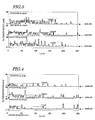
- FIGS. 3 and 4 are graphs showing how the Dy concentration varied in the depth direction in such a region of an R-Fe-B based rare-earth sintered magnet from a depth of 0 ⁇ m through a depth of 250 ⁇ m, in which Dy had already been diffused but from which the surface portion had not been removed yet.
- the abscissa represents the depth as measured from the surface of the magnet and the ordinate represents the Dy concentration (in wt%).
- the data shown in FIGS. 3 and 4 were collected under the same conditions except that a heat treatment was carried out on the sintered magnet body under mutually different sets of conditions during the Dy evaporation diffusion process. Specifically, the data shown in FIG. 3 was obtained by performing the Dy evaporation diffusion process with the heat treatment carried out at 900 °C for 120 minutes, while the data shown in FIG. 4 was obtained by performing the Dy evaporation diffusion process with the heat treatment carried out at 850 °C for 240 minutes. Under these two sets of heat treatment conditions, data was collected on sintered magnet bodies including 0 wt%, 2.5 wt%, and 5.0 wt% of Dy before being subjected to the diffusion process. In each of FIGS. 3 and 4 , the data about the sintered magnet bodies including 0 wt%, 2.5 wt%, and 5.0 wt% of Dy, respectively, are shown in this order (top to bottom). The details of Specific Example #1 will be described later.
- the layer including the heavy rare-earth element RH that had been introduced by evaporation diffusion process was present in the outer periphery of the main phase crystal grains and had an almost uniform composition.
- the level (or the height) of each of the dashed lines running horizontally indicates the concentration of Dy included in the RH (Dy) diffused layer of its associated sample sintered magnet body. It should be noted that the levels (or heights) of those dashed lines were set by detecting the concentration of Dy in the Dy diffused layer based on the intensity of Dy L ⁇ that had been measured with an EPMA.
- each of the baselines represents the concentration of Dy that was included in the main phase yet to be subjected to the diffusion process.
- peaks approximately on a level with the Dy concentration of the Dy diffused layer represent a region with an RH (Dy) diffused layer (i.e., the outer periphery of the main phase).
- peaks on the baseline represent either a region in which no Dy was introduced at all as a result of the diffusion process or a region in which the diffused layer was too thin to detect Dy.
- that region corresponds to an inner region of a main phase grain that no Dy reached by diffusion, a main phase grain with a Dy diffused layer that was too thin to detect any Dy, or a grain boundary phase.
- peaks exceeding the height indicated by the dashed lines represent a region where an Nd-Dy oxide was present at a grain boundary triple junction. It should be noted that it was determined, based on the concentrations of Nd and oxygen (not shown) that were also measured with an EPMA, which peaks represent what regions.
- the respective peaks have broad widths and almost no peaks are on a level with the baselines. This means that in the surface region of the magnet with a thickness of approximately 100 ⁇ m or less, there were a lot of main phase crystal grains in which Dy had diffused almost to their core.
- An RL-RH oxide such as the Nd-Dy oxide described above is present at the grain boundary triple junction of the R-Fe-B based rare-earth sintered magnet body of the present invention.
- Such an oxide is preferably present in at least one grain boundary triple junction, which is located at a depth of 100 ⁇ m or less under the surface of the sintered magnet body, and preferably has a higher RH concentration than any other portion.
- the grain boundary layer which is an RL-rich layer
- the grain boundary of the R-Fe-B based rare-earth sintered magnet body of the present invention has almost no heavy rare-earth element RH, except that RL-RH oxide, and has a lower RH concentration than the RH diffused layer.
- the heavy rare-earth element RH is included a lot on the grain boundary but a little in the main phase as described in Patent Document No. 4. Such a difference in the distribution of the heavy rare-earth element RH would probably be caused by a difference in diffusion process.
- the difference in the concentration of Dy between the core of those crystal grains and their peripheral (RL 1-x RH x ) 2 Fe 14 B (where 0.2 ⁇ x ⁇ 0.75) layer corresponds to the amount of Dy that has been introduced by diffusion, and is preferably 6.0 mass% or more. In this case, 6.0 mass% substantially corresponds to the mole fraction x of 0.2 in the compositional formula described above.
- the intragrain diffusion has hardly occurred at the depth of 20 ⁇ m under the surface of the sintered magnet body, from which the surface portion has already been removed, and the (RL 1-x RH x ) 2 Fe 14 B (where 0.2 ⁇ x ⁇ 0.75) layer that could be present in the outer periphery of the crystal grains of the R 2 Fe 14 B type compound will have a thickness that is at most 20% as large as the average grain size of the crystal grains of the R 2 Fe 14 B type compound.
- FIG. 5(a) shows a Dy L ⁇ characteristic X-ray image on a cross section of a sample magnet, which had had a Dy concentration of 5.0 wt% before being subjected to the diffusion process but which had already been subjected to the diffusion process, from its surface to a depth of approximately 80 ⁇ m under the surface.
- the intragrain diffusion rather advanced in the surface region of the magnet body, which is in agreement with the results shown in FIG. 3 .
- Portions with a high Dy L ⁇ intensity at the grain boundary triple junctions i.e., relatively bright portions shown in FIG. 5(a) represent Nd-Dy oxides.
- FIG. 5(b) is a Dy L ⁇ characteristic X-ray image on a cross section of the same magnet as the one shown in FIG. 5(a) , from which the surface portion had already been removed to a depth of 150 ⁇ m as measured from its surface, though.
- the Dy L ⁇ characteristic X-ray image shown in FIG. 5(b) corresponds to that of a magnet body, from which the surface portion has not been removed yet, in the range from a depth of 150 ⁇ m through a depth of 230 ⁇ m.
- the heavy rare-earth element RH distributed in the outer periphery of its main phase would certainly contribute to increasing the coercivity but the heavy rare-earth element RH that has diffused to reach the core of crystal grains would hardly contribute to increasing the coercivity.
- the coercivity has certainly been increased significantly due to the improvement of the magnetocrystalline anisotropy but the remanence (B r ) would have decreased because the magnetic moment of the heavy rare-earth element RH and that of Fe have mutually opposite directions. That is why the overall remanence (B r ) of the resultant magnet would somewhat decrease, too.
- the crystal grains that are located relatively close to the surface of the magnet body let Dy diffuse and reach their core, and include a lot of heavy rare-earth element RH that would just decrease the remanence without contributing to increasing the coercivity.
- the crystal grains as a whole should have increased coercivity. That is to say, as can be seen from the foregoing description, it has been widely believed that the deeper inside the magnet, the smaller the amount of RH diffused and reached, and therefore, the less effectively the coercivity should be increased.
- the present inventors carried out investigations to know how the magnetic properties of the sintered magnet body, from which the surface portion had been removed, were affected by the thickness of the surface portion removed.
- the best thickness of the surface portion to remove would differ according to the diffusion conditions, the present inventors discovered that the remanence that had once been decreased due to the addition of RH recovered if the surface portion were removed to a depth at which there was no RH that had been introduced by diffusion into the core of the main phase (specifically, until the RH diffused layer at a depth of 20 ⁇ m under the surface came to have a thickness of 2 ⁇ m or less).
- the crystal grains of the R 2 Fe 14 B type compound still had an RH diffused layer (i.e., with an increased RH concentration), which preferably has the composition (RL 1-x RH x ) 2 Fe 14 B (where 0.2 ⁇ x ⁇ 0.75) and has an average thickness of 0.5 ⁇ m or less.
- the sintered magnet body of the present invention (from which the surface portion has already been removed) has an (average) size of 1 mm to 4 mm in the thickness direction (i.e., the direction that intersects with a surface with the broadest area at right angles), then the difference ⁇ H cJ 1 in coercivity between the overall sintered magnet body and the rest of the sintered magnet body, from which the surface portions have been further removed by 200 ⁇ m, becomes 150 kA/m or less. This point will be described with reference to FIG. 6(a) . As shown in FIG.
- a surface region with a thickness of 1 mm as measured from the surface of the sintered magnet body is preferably divided into a first layer portion with a thickness of 500 ⁇ m as measured from the surface and a second layer portion that also has a thickness of 500 ⁇ m and that is located deeper inside the sintered magnet body than the first layer portion.
- the difference ⁇ H cJ 2 in coercivity between the first and second layer portions becomes 300 kA/m or less. This point will be described with reference to FIG. 6(b) . As shown in FIG.
- a surface region of a sintered magnet body 30 having a thickness of 1 mm, is divided into a first layer portion 30a with a thickness of 500 ⁇ m as measured from the surface and a second layer portion 30b that also has a thickness of 500 ⁇ m and that is located deeper inside the sintered magnet body 30 than the first layer portion 30a. Then, the difference ⁇ H cJ 2 in coercivity between the first and second layer portions 30a and 30b becomes 300 kA/m or less.
- the surface of the sintered magnet body is covered with a coating of a rare-earth metal, which is then diffused inside the magnet by heat treatment. That is why compared to the evaporation diffusion process of the present invention, the intragrain diffusion would have advanced more significantly and reached the core of the main phase crystal grains even deeper inside the magnet. For that reason, in the surface portion of the sintered magnet bodies disclosed in those documents, the RH diffused layer would have a thickness of well over 2 ⁇ m due to the intragrain diffusion of the heavy rare-earth element RH.
- the depth that the heavy rare-earth element RH can reach is shallower than the one realized by the evaporation diffusion process, and is usually as a matter of several ten ⁇ m in their working examples. That is why if the surface portion were removed from any of those sintered magnet bodies, the heavy rare-earth element RH that has been introduced intentionally by the heat treatment would be lost almost entirely, and therefore, the coercivity could be increased effectively.
- the heavy rare-earth element RH can be introduced deeper into the magnet body (to a depth of several hundred ⁇ m to 1,000 ⁇ m or more) with the intragrain diffusion minimized. For that reason, even if the surface portion was removed from the magnet body, the coercivity should hardly decrease compared to the magnet body that still has the surface portion.
- the “amount of the surface portion removed” herein means the thickness of the surface portion removed and corresponds to the depth as measured from the surface of the sintered magnet body that still has that surface portion.
- the surface portion is preferably removed to such a depth that the peaks of the diffused layer often agree with the baseline in FIGS. 3 and 4 , i.e., until a region where the heavy rare-earth element RH rarely reaches the core of the main phase crystal grains gets exposed.
- the surface portion is preferably removed to a depth of approximately 100 ⁇ m as measured from the surface.
- the surface portion is preferably removed to a depth of approximately 20 ⁇ m as measured from the surface.
- the thickness of the surface portion to remove is preferably determined so that the RH diffused layer that the crystal grains of the R 2 Fe 14 B type compound will have at a depth of 20 ⁇ m under the surface of the sintered magnet body when the surface portion is removed, i.e., the (RL 1-x RH x ) 2 Fe 14 B (where 0.2 ⁇ x ⁇ 0.75) layer, will have an average thickness of 2 ⁇ m or less.
- the average thickness of the (RL 1-x RH x ) 2 Fe 14 B (where 0.2 ⁇ x ⁇ 0.75) layer at a depth of 20 ⁇ m under the surface is supposed to be the average of the thicknesses of the (RL 1-x RH x ) 2 Fe 14 B (where 0.2 ⁇ x ⁇ 0.75) layer that have been measured at ten or more arbitrary main phase crystal grains at a depth of 20 ⁇ m under the surface.
- the average thickness of the RH diffused layer in the outer periphery of main phase crystal grains exceeded 2 ⁇ m, then only a minority of those main phases would be still free from the heavy rare-earth element RH diffused and the remanence could not be recovered effectively.
- the RH diffused layer has a thickness of 2 ⁇ m or less, then those main phase crystal grains that are still free from the heavy rare-earth element RH diffused will have a thickness of at least 1 ⁇ m, for example.
- the RH diffused layer preferably has a thickness of 1 ⁇ m or less, more preferably 0.5 ⁇ m or less. It should be noted that the thickness of the diffused layer could be measured on a cross section of the magnet body in the depth direction, for example.
- the RH diffused layer were too thin to get measured with an EPMA (e.g., if the RH diffused layer had a thickness of 0.5 ⁇ m or less), then its thickness could be measured with a TEM. Using a TEM, such a thin RH diffused layer can also be detected as long as its thickness is at least about 10 nm. That is why the lower limit of the thickness of the RH diffused layer detectable will be 10 nm. However, even such a thin RH diffused layer could still increase the coercivity sufficiently.
- the surface portion is more preferably removed to such a depth that the peaks of the RH diffused layer shown in FIGS. 3 and 4 are so low as the baseline that the Dy introduced by diffusion process is no longer detectable, i.e., a region in an ideal state where the heavy rare-earth element RH is distributed very thinly through diffusion in the outer periphery of the main phase crystal grains.
- the RH diffused layer has a thickness of 0.5 ⁇ m or less.
- the remanence B r can be recovered almost without decreasing the coercivity H cJ .
- the thickness of the surface portion removed is preferably 20 ⁇ m through 300 ⁇ m, more preferably from 50 ⁇ m through 200 ⁇ m.
- Table 2 summarizes how the thickness of the Dy diffused layer changed with that of the surface portion removed from various sintered magnet bodies in which Dy had been diffused by mutually different methods.
- the methods for diffusing Dy adopted were the evaporation diffusion process for use in the present invention and the conventional diffusion process (i.e., a heat treatment was carried out after a Dy film had been deposited).
- Samples prepared by the evaporation diffusion process were obtained by the same method as the one to make Sample A1 of EXAMPLE 1 to be described later. Thereafter, the surface portions of each of those sample sintered magnet bodies (which had dimensions of 7 mm square on both sides) were removed by grinding using a surface grinder to the depth shown in Table 2. Then, the thickness of the Dy diffused layer (as the average of thicknesses that had been measured at 10 points) at a depth of 20 ⁇ m under each of the two surfaces of the ground magnet body was estimated with a TEM.
- samples were also obtained by the conventional Dy diffusion process. Specifically, a Dy film was deposited to mutually different thicknesses on the surface of sintered magnet bodies by sputtering process and then thermally treated at 900 °C for 120 minutes. The Dy films thus deposited had thicknesses of 15 ⁇ m, 3 ⁇ m and 0.5 ⁇ m. As for the sintered magnet bodies on which Dy had been diffused in this manner, the surface portion was also removed from the magnets by grinding and then the thickness of the Dy diffused layer was also measured just as described above.
- Thickness reduced ( ⁇ m) Thickness of Dy diffused layer ( ⁇ m) Evaporation diffusion Dy deposited to 15 ⁇ m and then heat-treated Dy deposited to 3 ⁇ m and then heat-treated Dy deposited to 0.5 ⁇ m and then heat-treated 0 1.8 2.5 2.2 1.5 2 1.8 2.5 2.2 1.5 5 1.5 2.2 2.0 1.0 50 1.3 2.2 1.0 NA 100 1.0 2.2 0.5 NA 200 0.5 2.1 0.1 or less NA 500 0.3 1.8 NA NA 1000 0.1 or less 0.5 NA NA
- the diffused layer located at a depth of 20 ⁇ m under the surface of the magnet body, from which the surface portion had been removed by 5 ⁇ m, had a uniform composition in which x ( 0.37) had a dispersion of 10% or less.
- a magnet according to the present invention obtained by removing a surface portion to a depth of 5 ⁇ m from a magnet body that had gone through the evaporation diffusion process, had its surface portion further removed by 200 ⁇ m from the (machined) surface that had been exposed as a result of the former surface portion removal process, the resultant magnet (that had had its surface portion removed by 205 ⁇ m in total each side) had almost as high coercivity as the magnet body that had had its surface portion removed by 200 ⁇ m as shown in Table 3. And the difference ⁇ H cJ 1 in coercivity from the magnet body that had had its surface portion removed by 5 ⁇ m was 5 kA/m. According to the evaporation diffusion process, ⁇ H cJ 1 can be reduced to 150 kA/m or less, more favorably 100 kA/m or less.
- the Dy diffused layer in the main phase crystal grains in the surface region of the magnet body would have a thickness of more than 2.0 ⁇ m. That is why to recover B r by setting the thickness of the Dy diffused layer to be 2.0 ⁇ m or less, the surface portion of the magnet body should be removed to a depth of 500 ⁇ m or more.
- the Dy film were deposited to a reduced thickness (which was 0.5 ⁇ m in the experimental example described above) and if a decreased amount of Dy was diffused, the effect of increasing the coercivity of the overall magnet body would be very little and Dy diffused would go no farther than the superficial region of the magnet body. In that case, if the surface portion were removed by as much as 50 ⁇ m, then the effect of increasing the coercivity would be lost completely. Then, even with a TEM, the thickness of the Dy diffused layer could not be detected (i.e., there would be no diffused layer detectable).
- the evaluation method using ⁇ H cJ 1 can be used effectively in a situation where the magnet body has a thickness of 1 mm to 4 mm.
- the thickness of the magnet body exceeds 2 mm (and preferably reaches more than 4 mm), then not just the evaluation using ⁇ H cJ 1 described above but also the following evaluation method can be adopted as well.
- the surface region with a thickness of 1 mm as measured from the surface of a sintered magnet body was divided into a first layer portion that had a thickness of 500 ⁇ m as measured from the surface and a second layer portion that also had a thickness of 500 ⁇ m and that was located deeper inside the sintered magnet body than the first layer portion, and the difference ⁇ H cJ 2 in coercivity between the first and second layer portions was measured (see FIG. 6(b) ).
- Table 4 Evaporation diffusion Deposited to 15 ⁇ m and then heat-treated Deposited to 3 ⁇ m and then heat-treated Deposited to 0.5 ⁇ m and then heat-treated H cJ ⁇ H cJ 2 H cJ ⁇ H cJ 2 H cJ ⁇ H cJ 2 H cJ ⁇ H cJ 2 Shallower 500 ⁇ m of magnet body 1360 65 1390 100 1360 510 1330 480 Deeper 500 ⁇ m of magnet body 1295 1290 850 850
- the intragrain diffusion will hardly occur in the surface region of the sintered magnet body, and the heavy rare-earth element RH diffused can reach deeper inside the magnet compared to the conventional method. That is why even if the surface portion of the magnet body was removed, the effect of increasing the coercivity would never be lessened and only the remanence B r could be recovered. On top of that, the diffusion process can be carried out with little heavy rare-earth element RH deposited on the wall surfaces of the evaporation system.
- a bulk body of a heavy rare-earth element RH that is not easily vaporizable (or sublimable) and a rare-earth sintered magnet body are arranged close to each other in the processing chamber and both heated to a temperature of 700 °C to 1,000 °C, thereby reducing the vaporization (or sublimation) of the RH bulk body to the point that the growth rate of an RH film is not excessively higher than the rate of diffusion of RH into the magnet and diffusing the heavy rare-earth element RH, which has traveled to reach the surface of the sintered magnet body, into the magnet body quickly.
- the heavy rare-earth element RH hardly vaporizes (or sublimes) but diffuses actively in an R-Fe-B based rare-earth sintered magnet. For that reason, the grain boundary diffusion of the heavy rare-earth element RH into the magnet body can be accelerated more sharply than the film formation of the heavy rare-earth element RH on the surface of the magnet body.
- the heavy rare-earth element RH will diffuse and penetrate into the magnet at a higher rate than the heavy rare-earth element RH diffusing into the main phases that are located near the surface of the sintered magnet body.
- the heavy rare-earth element RH since the heavy rare-earth element RH is supplied onto the surface of the sintered magnet body with the growth rate of the RH film decreased and the temperature of the sintered magnet body is maintained at an appropriate level for diffusion, the heavy rare-earth element RH that has reached the surface of the magnet body quickly penetrates into the sintered magnet body by grain boundary diffusion. That is why even in the surface region of the magnet body, the "grain boundary diffusion" advances more preferentially than the "intragrain diffusion". As a result, the decrease in remanence B r can be minimized and the coercivity H cJ can be increased effectively.
- the R-Fe-B based rare-earth sintered magnet has a nucleation type coercivity generating mechanism. Therefore, if the magnetocrystalline anisotropy is increased in the outer periphery of a main phase, the nucleation of reverse magnetic domains can be reduced in the vicinity of the grain boundary phase surrounding the main phase. As a result, the coercivity H cJ of the main phase can be increased effectively as a whole. According to the evaporation diffusion process, the heavy rare-earth replacement layer can be formed in the outer periphery of the main phase not only in a surface region of the sintered magnet body but also deep inside the magnet.
- the magnetocrystalline anisotropy can be increased in the entire magnet and the coercivity H cJ of the overall magnet increases sufficiently. Therefore, the magnet, into which RH has been introduced by evaporation diffusion and from which the surface portion of the sintered magnet body has been removed after that, can have an increased coercivity H cJ almost without decreasing its remanence B r .
- the evaporation diffusion is preferably carried out at a higher temperature and in a higher vacuum than a situation where Dy is used.
- the heavy rare-earth element RH does not always have to be added to the material alloy. That is to say, a known R-Fe-B based rare-earth sintered magnet, including a light rare-earth element RL (which is at least one of Nd and Pr) as the rare-earth element R, may be provided and then the heavy rare-earth element RH may be diffused inward from the surface of the magnet. If only the conventional heavy rare-earth film were formed on the surface of the magnet, it would be difficult to diffuse the heavy rare-earth element RH deep inside the magnet even at an elevated diffusion temperature.
- the heavy rare-earth element RH can be supplied efficiently to even the outer periphery of the main phases that are located deep inside the sintered magnet body.
- the present invention is naturally applicable to an R-Fe-B based sintered magnet, to which the heavy rare-earth element RH was already added when it was a material alloy.
- the effect of the present invention would not be achieved sufficiently. For that reason, a relatively small amount of heavy rare-earth element RH may be added in that early stage.
- FIG. 7 illustrates an exemplary arrangement of sintered magnet bodies 2 and RH bulk bodies 4.
- the sintered magnet bodies 2 and the RH bulk bodies 4 are arranged so as to face each other with a predetermined gap left between them inside a processing chamber 6 made of a refractory metal.
- the processing chamber 6 shown in FIG. 7 includes a member for holding a plurality of sintered magnet bodies 2 and a member for holding the RH bulk body 4.
- the sintered magnet bodies 2 and the upper RH bulk body 4 are held on a net 8 made of Nb.
- the sintered magnet bodies 2 and the RH bulk bodies 4 do not have to be held in this way but may also be held using any other member. Nevertheless, a member that closes the gap between the sintered magnet bodies 2 and the RH bulk bodies 4 should not be used.
- “facing” means that the sintered magnet bodies and the RH bulk bodies are opposed to each other without having their gap closed. Also, even if two members are arranged "so as to face each other", it does not necessarily mean that those two members are arranged such that their principal surfaces are parallel to each other.
- the temperature of the processing chamber 6 is raised.
- the temperature of the processing chamber 6 is controlled to the range of 700 °C to 1,000 °C, more preferably to the range of 850 °C to 950 °C.
- the heavy rare-earth element RH has a very low vapor pressure and hardly vaporizes.
- a heavy rare-earth element RH, vaporized from an RH bulk body 4 be unable to be supplied and deposited on the surface of the sintered magnet body 2.
- the present inventors discovered that by arranging the sintered magnet body 2 and the RH bulk body 4 close to each other, not in contact with each other, a heavy rare-earth metal could be supplied at as low a rate as several ⁇ m per hour (e.g., in the range of 0.5 ⁇ m/hr to 5 ⁇ m/hr) on the surface of the sintered magnet body 2.
- a heavy rare-earth metal could be supplied at as low a rate as several ⁇ m per hour (e.g., in the range of 0.5 ⁇ m/hr to 5 ⁇ m/hr) on the surface of the sintered magnet body 2.
- the temperature of the sintered magnet body 2 within an appropriate range such that the temperature of the sintered magnet body 2 was equal to or higher than that of the RH bulk body 4, the heavy rare-earth metal RH that had been supplied in vapor phase could be diffused deep into the sintered magnet body 2 as it was.
- This temperature range is a preferred one in which the RH metal diffuses inward through the grain
- RH that has vaporized just slightly as described above is supplied at a low rate on the surface of the sintered magnet body. For that reason, there is no need to heat the processing chamber to a high temperature that exceeds 1,000 °C or apply a voltage to the sintered magnet body or RH bulk body as in the conventional process of depositing RH by vapor phase deposition.
- the heavy rare-earth element RH that has arrived at the surface of the sintered magnet body is quickly diffused inside the magnet body.
- the RH bulk body and the sintered magnet body preferably both have a temperature falling within the range of 700 °C to 1,000 °C.
- the gap between the sintered magnet body 2 and the RH bulk body 4 is preferably set to fall within the range of 0.1 mm to 300 mm. This gap is more preferably 1 mm to 50 mm, even more preferably 20 mm or less, and most preferably 10 mm or less. As long as such a distance can be kept between them, the sintered magnet bodies 2 and the RH bulk bodies 4 may be arranged either vertically or horizontally or may even be moved relative to each other. Nevertheless, the distance between the sintered magnet bodies 2 and the RH bulk bodies 4 preferably remains the same during the evaporation diffusion process. Also, an embodiment in which the sintered magnet bodies are contained in a rotating barrel and processed while be stirred up is not preferred. Furthermore, since the vaporized RH can create a uniform RH atmosphere within the distance range defined above, the area of their opposing surfaces is not particularly limited but even their narrowest surfaces may face each other.
- the present inventors discovered and confirmed via experiments that when the RH bulk bodies were arranged perpendicularly to the magnetization direction (i.e., the c-axis direction) of the sintered magnet bodies 2, RH could diffuse into the sintered magnet bodies 2 most efficiently. This is probably because when RH diffuses inward through the grain boundary phase of the sintered magnet bodies 2, the diffusion rate in the magnetization direction is higher than the rate in the perpendicular direction. That difference in diffusion rate between the magnetization and perpendicular directions should be caused by a difference in anisotropy due to the crystal structure.
- a good distance should be kept between an evaporating material supply section and the target being processed because a mechanism surrounding the evaporating material supply section or the target holding member such as a barrel would make interference and the evaporating material supply section should be exposed to an electron beam or an ion beam.
- the evaporating material supply section (corresponding to the RH bulk body 4 ) and the target being processed (corresponding to the sintered magnet body 2 ) have never been arranged so close to each other as in the evaporation diffusion process.
- the evaporating material is heated to a rather high temperature and vaporized sufficiently, plenty of the evaporating material could not be supplied onto the target being processed.
- the RH metal can be supplied onto the surface of the magnet just by controlling the temperature of the overall processing chamber without using any special mechanism for vaporizing (or subliming) the evaporating material.
- the "processing chamber” broadly refers to a space in which the sintered magnet bodies 2 and the RH bulk bodies 4 are arranged.
- the processing chamber may mean the processing chamber of a heat treatment furnace but may also mean a process vessel housed in such a processing chamber.
- the RH metal vaporizes little but the sintered magnet body and the RH bulk body are arranged close to each other but not in contact with each other. That is why the RH metal vaporized can be supplied onto the surface of the sintered magnet body efficiently and is hardly deposited on the wall surfaces of the processing chamber. Furthermore, if the wall surfaces of the processing chamber are made of a heat-resistant alloy including Nb, for example, a ceramic, or any other material that does not react to RH, then the RH metal deposited on the wall surfaces will vaporize again and will reach the surface of the sintered magnet body after all. As a result, it is possible to avoid an unwanted situation where the heavy rare-earth element RH, which is one of valuable rare natural resources, is wasted in vain.
- the RH bulk body Within the processing temperature range of the diffusion process to be carried out as an evaporation diffusion process, the RH bulk body never melts or softens but the RH metal vaporizes (sublimes) from its surface. For that reason, the RH bulk body does not change its appearance significantly after having gone through the process step just once, and therefore, can be used repeatedly a number of times.
- the number of sintered magnet bodies that can be loaded into a processing chamber with the same capacity can be increased. That is to say, high loadability is realized.
- a normal vacuum heat treatment furnace may be used and the increase in manufacturing cost can be avoided, which is very beneficial in practical use.
- an inert atmosphere is preferably maintained inside the processing chamber.
- the "inert atmosphere” refers to a vacuum or an atmosphere filled with an inert gas.
- the "inert gas” may be a rare gas such as argon (Ar) gas but may also be any other gas as long as the gas is not chemically reactive between the RH bulk body and the sintered magnet body.
- the pressure of the inert gas is reduced so as to be lower than the atmospheric pressure. If the pressure of the atmosphere inside the processing chamber were close to the atmospheric pressure, then the RH metal could not be supplied easily from the RH bulk body to the surface of the sintered magnet body.
- the amount of the RH metal diffused is determined by the rate of diffusion from the surface of the magnet toward the inner portion thereof, it should be enough to lower the pressure of the atmosphere inside the processing chamber to 10 2 Pa or less, for example. That is to say, even if the pressure of the atmosphere inside the processing chamber were further lowered, the amount of the RH metal diffused (and eventually the degree of increase in coercivity) would not change significantly.
- the amount of the RH metal diffused is more sensitive to the temperature of the sintered magnet body, rather than the pressure.
- the RH metal that has traveled to reach the surface of the sintered magnet body starts to diffuse toward the inner portion of the magnet through the grain boundary phase under the driving forces generated by the heat of the atmosphere and the difference in RH concentration at the interface of the magnet.
- a portion of the light rare-earth element RL in the R 2 Fe 14 B phase is replaced with the heavy rare-earth element RH that has diffused and penetrated through the surface of the magnet.
- a layer including the heavy rare-earth element RH at a high concentration is formed in the outer periphery of the R 2 Fe 14 B phase.
- the magnetocrystalline anisotropy can be improved in the outer periphery of the main phase grain and the coercivity H cJ can be increased. That is to say, even by using a small amount of RH metal, the heavy rare-earth element RH can diffuse and penetrate deeper into the magnet and the RH diffused layer can be formed in the outer periphery of the main phase efficiently. As a result, the coercivity H cJ of the overall magnet can be increased with the decrease in remanence B r minimized.
- the rate of deposition of the heavy rare-earth element RH such as Dy on the surface of the sintered magnet body is much higher than the rate of diffusion of the heavy rare-earth element RH toward the inner portion of the sintered magnet body (i.e., a diffusion rate).
- an RH film is deposited to a thickness of several ⁇ m or more on the surface of the sintered magnet body and then the heavy rare-earth element RH is diffused from that RH film in solid phase toward the inner portion of the sintered magnet body.
- the heavy rare-earth element RH that has been supplied from the RH film in solid phase, not in vapor phase will diffuse under the driving force generated by a steep concentration gradient at the interface between the magnet body and the RH film.
- the heavy rare-earth element RH not only diffuses through the grain boundary but also makes an intragrain diffusion inside the main phase that is located in the surface region of the magnet body, thus causing a significant decrease in remanence B r .
- That region in which the heavy rare-earth element RH makes such an intragrain diffusion inside the main phase to decrease the remanence is limited to the surface region of the sintered magnet body (with a thickness of 100 ⁇ m to several hundred ⁇ m, for example). Therefore, at least that portion should be removed.
- the heavy rare-earth element RH such as Dy that has vaporized (or sublimed) from the RH bulk bodies would impinge on the surface of the sintered magnet body and then quickly diffuse toward the inner portion of the sintered magnet body directly in vapor phase, without passing through the RH film in solid phase. That is why RH would diffuse inside the magnet not because of the driving force generated by the steep concentration gradient at the interface between the magnet body and the RH film as in the method in which an RH film is deposited and then thermally treated, but based on another principle such as chemical affinity.
- the heavy rare-earth element RH will diffuse through the grain boundary phase at a higher rate and penetrate deeper into the sintered magnet body before diffusing and reaching the core of the main phase that is located in the surface region of the magnet body.
- a unique structure that cannot be obtained by any method other than the evaporation diffusion process disclosed herein can be obtained, thus improving the performance of the magnet by leaps and bounds. That is to say, the evaporation diffusion process is advantageous in that the intragrain diffusion will not occur easily even in the surface region of the magnet body and that the portion to remove may have just a small thickness.
- the concentration of the RH to diffuse and introduce is preferably within the range of 0.05 wt% to 1.5 wt% of the overall magnet. This concentration range is preferred because at an RH concentration of more than 1.5 wt%, the intragrain diffusion would occur so much even in the crystal grains in the sintered magnet body that the decrease in remanence B r could be out of control even if the surface portion were removed but because the increase in coercivity H cJ would be insufficient at an RH concentration of less than 0.05 wt%.
- the process time means a period of time in which the RH bulk body and the sintered magnet body have temperatures of 700 °C to 1,000 °C and pressures of 10 -5 Pa to 500 Pa. Thus, during this process time, their temperatures and pressures are not always kept constant.
- the surface state of the sintered magnet, into which RH has not been diffused or introduced yet, is preferably as close to a metal state as possible to allow the RH to diffuse and penetrate easily.
- the sintered magnet is preferably subjected to an activation treatment such as acid cleaning or blast cleaning in advance.
- an activation treatment such as acid cleaning or blast cleaning in advance.
- the surface of the sintered magnet body may also have been oxidized to a certain degree as is observed right after a sintering process or a cutting process. Since an R-Fe-B based sintered magnet exhibits some anisotropy while shrinking during sintering, the magnet is normally subjected to a size adjustment after the sintering process. On the other hand, according to a process other than the evaporation diffusion process, the surface of the sintered magnet body, on which an RH film has not been deposited yet, should be polished to remove a surface oxide layer from it. For that reason, the size adjustment is usually done before the RH film is deposited.
- the size adjustment can also be done on an as-sintered magnet, of which the surface has been rather oxidized. Consequently, the size adjustment and the removal of the surface portion from the magnet body can be done at the same time, which is advantageous.
- the heavy rare-earth element RH can be diffused mainly through the grain boundary phase. For that reason, the heavy rare-earth element RH can be diffused deeper into the magnet more efficiently by controlling the process time.
- the shape and size of the RH bulk bodies are not particularly limited.
- the RH bulk bodies may have a plate shape or an indefinite shape (e.g., a stone shape).
- the RH bulk bodies may have a lot of very small holes with diameters of several ten ⁇ m.
- the RH bulk bodies are preferably made of either an RH metal including at least one heavy rare-earth element RH or an alloy including RH. Also, the higher the vapor pressure of the material of the RH bulk bodies, the greater the amount of RH that can be introduced per unit time, and the more efficient.
- Oxides, fluorides and nitrides including a heavy rare-earth element RH have so low vapor pressures that evaporation diffusion hardly occurs under the conditions falling within these ranges of temperatures and degrees of vacuum. For that reason, even if the RH bulk bodies are made of an oxide, a fluoride or a nitride including the heavy rare-earth element RH, the coercivity cannot be increased effectively.
- an alloy including 25 mass% to 40 mass% of a light rare-earth element RL, 0.6 mass% to 1.6 mass% of B (boron) and Fe and inevitably contained impurities as the balance is provided.
- a portion of B may be replaced with C (carbon) and a portion (at most 50 at%) of Fe may be replaced with another transition metal element such as Co or Ni.
- this alloy may contain about 0.01 mass% to about 1.0 mass% of at least one additive element M that is selected from the group consisting of Al, Si, Ti, V, Cr, Mn, Ni, Cu, Zn, Ga, Zr, Nb, Mo, Ag, In, Sn, Hf, Ta, W, Pb and Bi.
- Such an alloy is preferably made by quenching a melt of a material alloy by strip casting, for example.
- a method of making a rapidly solidified alloy by strip casting will be described.
- a material alloy with the composition described above is melted by induction heating within an argon atmosphere to make a melt of the material alloy.
- this melt is kept heated at about 1,350 °C and then quenched by single roller process, thereby obtaining a flake-like alloy block with a thickness of about 0.3 mm.
- the alloy block thus obtained is pulverized into flakes with a size of 1 mm to 10 mm before being subjected to the next hydrogen pulverization process.
- Such a method of making a material alloy by strip casting is disclosed in United States Patent No. 5,383,978 , for example.
- the material alloy block that has been coarsely pulverized into flakes is loaded into a hydrogen furnace and then subjected to a hydrogen decrepitation process (which will be sometimes referred to herein as a "hydrogen pulverization process") within the hydrogen furnace.
- a hydrogen decrepitation process which will be sometimes referred to herein as a "hydrogen pulverization process"
- the coarsely pulverized alloy powder is preferably unloaded from the hydrogen furnace in an inert atmosphere so as not to be exposed to the air. This should prevent the coarsely pulverized powder from being oxidized or generating heat and would eventually improve the magnetic properties of the resultant magnet.
- the rare-earth alloy is pulverized to sizes of about 0.1 mm to several millimeters with a mean particle size of 500 ⁇ m or less.
- the decrepitated material alloy is preferably further crushed to finer sizes and cooled. If the material alloy unloaded still has a relatively high temperature, then the alloy should be cooled for a longer time.
- the coarsely pulverized powder is finely pulverized with a jet mill pulverizing machine.
- a cyclone classifier is connected to the jet mill pulverizing machine for use in this preferred embodiment.
- the jet mill pulverizing machine is fed with the rare-earth alloy that has been coarsely pulverized in the coarse pulverization process (i.e., the coarsely pulverized powder) and gets the powder further pulverized by its pulverizer.
- the powder, which has been pulverized by the pulverizer is then collected in a collecting tank by way of the cyclone classifier.
- a finely pulverized powder with sizes of about 0.1 ⁇ m to about 20 ⁇ m (typically 3 ⁇ m to 5 ⁇ m) can be obtained.
- the pulverizing machine for use in such a fine pulverization process does not have to be a jet mill but may also be an attritor or a ball mill.
- a lubricant such as zinc stearate may be added as an aid for the pulverization process.
- 0.3 wt% of lubricant is added to, and mixed with, the magnetic powder, obtained by the method described above, in a rocking mixer, for example, thereby coating the surface of the alloy powder particles with the lubricant.
- the magnetic powder prepared by the method described above is compacted under an aligning magnetic field using a known press machine.
- the aligning magnetic field to be applied may have a strength of 1.5 to 1.7 tesla (T), for example.
- the compacting pressure is set such that the green compact has a green density of about 4 g/cm 3 to about 4.5 g/cm 3 .
- the powder compact described above is preferably sequentially subjected to the process of maintaining the compact at a temperature of 650 °C to 1,000 °C for 10 to 240 minutes and then to the process of further sintering the compact at a higher temperature (of 1,000 °C to 1,200 °C, for example) than in the maintaining process.
- a liquid phase is produced during the sintering process (i.e., when the temperature is in the range of 650 °C to 1,000 °C)
- the R-rich phase on the grain boundary phase starts to melt to produce the liquid phase.
- the sintering process advances to form a sintered magnet body eventually.
- the sintered magnet body can also be subjected to the evaporation diffusion process even if its surface has been oxidized as described above. For that reason, the sintered magnet body may be subjected to an aging treatment (at a temperature of 400 °C to 700 °C) or machined to adjust its size.
- the heavy rare-earth element RH is made to diffuse and penetrate efficiently into the sintered magnet body thus obtained, thereby increasing its coercivity H cJ .
- an RH bulk body, including the heavy rare-earth element RH, and a sintered magnet body are put into the processing chamber shown in FIG. 7 and then heated, thereby diffusing the heavy rare-earth element RH into the sintered magnet body while supplying the heavy rare-earth element RH from the RH bulk body onto the surface of the sintered magnet body simultaneously.
- the temperature of the sintered magnet body is preferably set equal to or higher than that of the bulk body.
- the temperature of the sintered magnet body when the temperature of the sintered magnet body is equal to or higher than that of the bulk body, it means that the difference in temperature between the sintered magnet body and the bulk body is within 20 °C.
- the temperatures of the RH bulk body and the sintered magnet body preferably both fall within the range of 700 °C to 1,000 °C.
- the gap between the sintered magnet body and the RH bulk body should be within the range of 0.1 mm to 300 mm, preferably 3 mm to 100 mm, and more preferably 4 mm to 50 mm, as described above.
- the pressure of the atmospheric gas during the evaporation diffusion process preferably falls within the range of 10 -5 Pa to 500 Pa. Then, the evaporation diffusion process can be carried out smoothly with the vaporization (sublimation) of the RH bulk body advanced appropriately. To carry out the evaporation diffusion process efficiently, the pressure of the atmospheric gas preferably falls within the range of 10 -3 Pa to 1 Pa. Furthermore, the amount of time for maintaining the temperatures of the RH bulk body and the sintered magnet body within the range of 700 °C to 1,000 °C is preferably 10 to 600 minutes.
- time for maintaining the temperatures refers to a period in which the RH bulk body and the sintered magnet body have temperatures varying within the range of 700 °C to 1,000 °C and pressures varying within the range of 10 -5 Pa to 500 Pa and does not necessarily refer to a period in which the RH bulk body and sintered magnet body have their temperatures and pressures fixed at a particular temperature and a particular pressure.
- the diffusion process of this preferred embodiment is not sensitive to the surface status of the sintered magnet body, and therefore, a film of Al, Zn or Sn may be deposited on the surface of the sintered magnet body before the diffusion process. This is because Al, Zn and Sn are lowmelting metals and because a small amount of Al, Zn or Sn would not deteriorate the magnetic properties or would not interfere with the diffusion, either.
- the bulk body does not have to be made of a single element but may include an alloy of a heavy rare-earth element RH and an element X, which is at least one element selected from the group consisting of Nd, Pr, La, Ce, Al, Zn, Sn, Cu, Co, Fe, Ag and In.
- element X is at least one element selected from the group consisting of Nd, Pr, La, Ce, Al, Zn, Sn, Cu, Co, Fe, Ag and In.
- Such an element X would lower the melting point of the grain boundary phase and would hopefully promote the grain boundary diffusion of the heavy rare-earth element RH.
- the heavy rare-earth element RH and the element X can be not only evaporated and supplied onto the surface of the magnet but also diffused into the magnet through the grain boundary phase (Nd-rich phase) that has turned into a liquid phase preferentially.
- the element X is preferably Nd and/or Pr because in that case, the element X would compensate for the Nd and/or Pr that has vaporized.
- an additional heat treatment process may be carried out.
- the additional heat treatment process may be carried out just by thermally treating the magnet with the partial pressure of Ar increased to about 500 Pa after the diffusion process such that the heavy rare-earth element RH will not vaporize.
- the heat treatment may be carried out without putting the RH bulk bodies.
- the processing temperature is preferably 700 °C to 1,000 °C, more preferably 800 °C to 950 °C. Even more preferably, the additional heat treatment temperature is equal to or lower than the processing temperature of the diffusion process.
- This additional heat treatment process is particularly effective when carried out on a sintered magnet body with a thickness of 3 mm or more. This is because if the sintered magnet body is rather thick, then it is difficult to make the heavy rare-earth element RH diffuse and reach deep inside the magnet body and close to its core. That is why even if the coercivity of the sintered magnet body as a whole has increased, the coercivity H cJ could still have hardly increased at its core. As shown in FIG. 1 , when the evaporation diffusion process is over, there will be some amount of heavy rare-earth element RH, which would not contribute to increasing the coercivity H cJ , in the grain boundary phase near the surface of the sintered magnet body. Thus, by performing this additional heat treatment process, that heavy rare-earth element RH can be diffused even closer to the main phase deep inside the sintered magnet body. As a result, the coercivity H cJ will increase at the core of the magnet body, too.
- the sintered magnet body is as thick as 3 mm or more, for example, a magnet, of which the remanence B r has hardly decreased and of which the coercivity H cJ has increased right to its core, can be provided.
- a difference ⁇ H cJ 3 in coercivity between respective portions with a thickness of 1 mm that have the highest and the lowest coercivities in the thickness direction of the sintered magnet body will be within the range of 80 kA/m to 200 kA/m.
- an aging treatment is also carried out at a temperature of 400 °C to 700 °C. If the additional heat treatment is carried out at a temperature of 700 °C to 1,000 °C, the aging treatment is preferably performed after the additional heat treatment has ended. The additional heat treatment and the aging treatment may be conducted in the same processing chamber.
- a surface portion is removed from the magnet body.
- a preferred thickness of the surface portion to remove will vary according to the diffusion process conditions as described above. However, by setting the thickness of the surface portion to remove within the range of 5 ⁇ m to 500 ⁇ m, the remanence B r can be recovered without decreasing the coercivity H cJ , compared to the magnet body that has just gone through the diffusion process. This range is preferred for the following reasons. Specifically, if the thickness of the surface portion to remove were smaller than 5 ⁇ m, then a portion in which the intragrain diffusion of the heavy rare-earth element RH has occurred significantly would remain, and therefore, the remanence B r could not be recovered sufficiently.
- the thickness of the surface portion to remove exceeded 500 ⁇ m, then the remanence B r could certainly be recovered but the coercivity H cJ could not be increased sufficiently. As a result, the coercivity H cJ would be lower than that of the magnet body that has just gone through the diffusion process.
- the thickness of the surface portion to remove preferably falls within the range of 20 ⁇ m to 300 ⁇ m, more preferably within the range of 50 ⁇ m to 200 ⁇ m.
- the surface portion does not have to be removed by any particular technique but may be removed by a normal technique such as grinding or polishing.
- the sintered magnet body that has gone through the surface portion removing process is preferably subjected to some surface treatment, which may be a known one such as Al evaporation, electrical Ni plating or resin coating. Before the surface treatment, the sintered magnet body may also be subjected to a known pre-treatment such as sandblast abrasion process, barrel abrasion process, or etching process.
- some surface treatment which may be a known one such as Al evaporation, electrical Ni plating or resin coating.
- the sintered magnet body may also be subjected to a known pre-treatment such as sandblast abrasion process, barrel abrasion process, or etching process.
- the light rare-earth element RL On the surface of the sintered magnet body in which the heavy rare-earth element RH has already been diffused by evaporation diffusion process but from which the surface portion has not been removed yet, there is the light rare-earth element RL, which has been present in the grain boundary of the sintered magnet body and which now has an increased concentration due to the inter-diffusion between itself and RH.
- the light rare-earth element RL reacts to oxygen in the atmosphere to produce an oxide or a hydroxide on the surface of the sintered magnet body.
- the surface portion of the sintered magnet body is removed to a depth of 5 ⁇ m or more. That is why once the surface portion has been removed, there will no longer be such RL oxide or RL hydroxide on the surface of the sintered magnet body.
- the "sintered magnet body” and the “magnet body” of the present invention are supposed to have not been subjected to the surface portion removing process yet, while the “sintered magnet” and the “magnet” are supposed to include the “sintered magnet body” and the “magnet” and have been subjected to the surface treatment as needed, for the sake of convenience.
- a vessel was loaded with those thin alloy flakes and then introduced into a hydrogen pulverizer, which was filled with a hydrogen gas atmosphere at a pressure of 500 kPa.
- hydrogen was absorbed into the thin alloy flakes at room temperature and then desorbed.
- the thin alloy flakes were decrepitated to obtain a powder in indefinite shapes with sizes of about 0.15 mm to about 0.2 mm.
- the fine powder thus obtained was compacted with a press machine to make a powder compact. More specifically, the powder particles were pressed and compacted while being aligned with a magnetic field applied. Thereafter, the powder compact was unloaded from the press machine and then subjected to a sintering process at 1,020 °C for four hours in a vacuum furnace, thus obtaining sintered blocks, which were then machined to obtain three sintered magnet bodies (Prototypes #1 to #3) having a thickness of 3 mm (in the magnetizing direction), a length of 7 mm and a width of 7 mm and including Dy in 0 mass%, 2.5 mass% and 5.0 mass%, respectively.
- These sintered magnet bodies were acid-cleaned with a 0.3% nitric acid aqueous solution, dried, and then arranged in a process vessel with the configuration shown in FIG. 7 .
- the process vessel for use in this preferred embodiment was made of Mo and included a member for holding a plurality of sintered magnet bodies and a member for holding two RH bulk bodies. A gap of about 5 mm to about 9 mm was left between the sintered magnet bodies and the RH bulk bodies.
- the RH bulk bodies were made of Dy with a purity of 99.9% and had dimensions of 30 mm ⁇ 30 mm ⁇ 5 mm.
- the process vessel shown in FIG. 7 was heated in a vacuum heat treatment furnace at an atmospheric gas pressure of 1 ⁇ 10 -2 Pa and at a temperature of 900 °C for 120 minutes, thereby conducting a heat treatment. After that, an aging treatment was carried out at a pressure of 2 Pa and at a temperature of 500 °C for 120 minutes.
- Diffusion process conditions A, B and C Table 6 Diffusion process conditions Thickness of surface portion removed A Evaporation diffusion at 900 °C in 120 minutes 100 ⁇ m B Evaporation diffusion at 850 °C in 240 minutes 50 ⁇ m C Deposition of Dy by sputtering and post-deposition heat treatment at 900 °C in 120 minutes 100 ⁇ m
- samples obtained by subjecting Prototypes #1 to #3 to the diffusion process under the diffusion process condition A will be referred to herein as “Samples A1, A2 and A3".
- samples obtained by subjecting Prototypes #1 to #3 to the diffusion process under the diffusion process condition B will be referred to herein as “Samples B1, B2 and B3”.
- the diffusion process condition C was the condition of a diffusion process that was carried out on a comparative example.
- a sample obtained by subjecting Prototype #1 to the diffusion process under the diffusion process condition C will be referred to herein as "Sample C1".
- heat treatment temperature will mean herein the temperature of the sintered magnet bodies and that of the RH bulk bodies, which is approximately equal to that of the sintered magnet bodies, unless otherwise stated.
- a Dy film was deposited to a thickness of approximately 15 ⁇ m on the surface of Prototype #1 by sputtering process, and then subjected to a heat treatment process at the same heat treatment temperature and in the same amount of time as the evaporation diffusion process on Sample A1, thereby obtaining Sample C1. It was discovered that in Sample C1, the ingrain diffusion had advanced to reach a depth of around 500 ⁇ m.
- Samples A1 to A3 and Sample C1 had their magnet body surface portions (having dimensions of 7 mm square on both sides) removed to a depth of approximately 100 ⁇ m each side.
- Samples B1 to B3 had their magnet body surface portions (having dimensions of 7 mm square on both sides) removed to a depth of approximately 50 ⁇ m each side.
- their magnetic properties including the remanence B r and the coercivity H cJ ) were measured with a B-H tracer. The results of the measurements are shown in the following Table 7.
- the magnet ⁇ H cJ 1 was 150 kA/m and there was a relatively big difference in coercivity between its magnet body surface portions and its portions deeper by 200 ⁇ m.
- Table 7 Dy concentration Before surface portion was removed After surface portion was removed After surface portion was further removed by 200 ⁇ m B r [T] H cJ [kA/m] B r [T] H cJ [kA/m] H cJ [kA/m] ⁇ H cJ 1 [kA/m] Prototype 1 0 mass% 1.40 850 1.40 850 850 0 A1 1.38 1280 1.40 1270 1240 30 B1 1.39 1280 1.40 1270 1200 70 C1 1.36 1250 1.37 1220 1070 150 Prototype 2 2.5 mass% 1.33 1380 1.33 1380 1380 0 A2 1.31 1860 1.33 1850 1810 40 B2 1.31 1800 1.33 1800 1710 90 Prototype 3 5.0 mass% 1.27 1780 1.27 1780 17
- the thickness of each of these diffused layers was calculated as the average of the thicknesses measured at ten arbitrary points in main phase crystal grains.
- Sample A1 the Dy diffused layer in a single main phase crystal grain, located at a depth of around 20 ⁇ m under the surface of the magnet body, was analyzed at ten arbitrary points with a TEM. The results are shown in the following Table 9. According to Table 9, x had a maximum value of 0.386 and a minimum value of 0.374, and the dispersion of the x values was 10% or less. When the present inventors carried out a similar analysis on the other samples A2, A3 and B1 to B3, we confirmed that the x values had a dispersion of 10% or less. Also, when looking into a cross-sectional structure of Sample C1 at a depth of approximately 20 ⁇ m under the surface of the magnet body, we discovered that Dy diffused reached the vicinity of the core of the main phase.
- sintered blocks were made by the same method as the one adopted in the first specific example described above. Then, by machining those sintered blocks, sintered magnet bodies having a length of 20 mm and a width of 20 mm and having their thickness varied from 3 mm through 7 mm in the magnetization direction were obtained as Prototypes #4, #5 and #6.
- These sintered magnet bodies were acid-cleaned with a 0.3% nitric acid aqueous solution, dried, and then arranged in a process vessel with the configuration shown in FIG. 7 .
- the process vessel for use in this preferred embodiment was made of Mo and included a member for holding a plurality of sintered magnet bodies and a member for holding two RH bulk bodies. A gap of about 5 mm to about 10 mm was left between the sintered magnet bodies and the RH bulk bodies.
- the RH bulk bodies were made of Dy with a purity of 99.9% and had dimensions of 30 mm ⁇ 30 mm ⁇ 5 mm.
- the process vessel shown in FIG. 7 was heated in a vacuum heat treatment furnace at an atmospheric gas pressure of 1 ⁇ 10 -2 Pa and at a temperature of 900 °C for 1 to 5 hours, thereby conducting a heat treatment. After that, an aging treatment was carried out at a pressure of 2 Pa and at a temperature of 500 °C for two hours. Thereafter, the surface portion of those sintered magnet bodies was ground and removed by 50 ⁇ m using a surface grinder, thereby obtaining Reference Examples #4 through #6. And the magnetic properties (i.e., the bulk properties) of those Reference Examples were measured.
- those reference examples were sliced at regular steps of 1 mm in the magnetization direction to obtain sintered magnet bodies having a length of 7 mm, a width of 7 mm and a thickness of 1 mm in the magnetization direction. And then their magnetic properties (which will be referred to herein as "sliced properties") were measured.
- Table 12 Sample Magnet thickness Surface portion (1 mm) After the surface region (1 mm) was divided into two halves H cJ -max (kA/m) Shallower 500 ⁇ m (kA/m) Deeper 500 ⁇ m (kA/m) ⁇ H cJ 2 (kA/m) Reference 4 3 mm 2140 2160 2100 60 Reference 5 5 mm 2080 2120 2010 110 Reference 6 7 mm 2050 2110 1960 150 Example 4 3 mm 2150 2160 2130 30 Example 5 5 mm 2090 2120 2060 60 60 Example 6 7 mm 2070 2120 2030 90
- Prototype #5 of EXAMPLE 2 the process vessel shown in FIG. 7 was heated in a vacuum heat treatment furnace at an atmospheric gas pressure of 1 ⁇ 10 -2 Pa and at a temperature of 800 °C or 850 °C for 5 to 10 hours, thereby conducting a heat treatment. After that, an aging treatment was carried out at a pressure of 2 Pa and at a temperature of 500 °C for two hours. Thereafter, the surface portion of the sintered magnet body was ground and removed by 20 ⁇ m using a surface grinder, thereby obtaining Specific Examples #7 and #8.
- those specific examples were sliced at regular steps of 1 mm in the magnetization direction to obtain sintered magnet bodies having a length of 7 mm, a width of 7 mm and a thickness of 1 mm in the magnetization direction. And then their magnetic properties (which will be referred to herein as "sliced properties") were measured.
- a sintered block was made by the same method as the one adopted in the first specific example described above. Then, by machining that sintered block, a sintered magnet body having a length of 20 mm and a width of 20 mm and a thickness of 5 mm in the magnetization direction was obtained as Prototype #7.
- That sintered magnet body was acid-cleaned with a 0.3% nitric acid aqueous solution, dried, and then arranged in a process vessel with the configuration shown in FIG. 7 .
- the process vessel for use in this preferred embodiment was made of Mo and included a member for holding a plurality of sintered magnet bodies and a member for holding two RH bulk bodies. A gap of about 5 mm to about 10 mm was left between the sintered magnet bodies and the RH bulk bodies.
- the RH bulk bodies were made of Dy with a purity of 99.9% and had dimensions of 30 mm ⁇ 30 mm ⁇ 5 mm.
- the process vessel shown in FIG. 7 was heated in a vacuum heat treatment furnace at an atmospheric gas pressure of 1 ⁇ 10 -2 Pa and at a temperature of 900 °C for 4 hours, thereby conducting a heat treatment. After that, an aging treatment was carried out at a pressure of 2 Pa and at a temperature of 500 °C for two hours to obtain Reference Example #7.
- the magnetic properties (i.e., the bulk properties) of that reference example were measured and then the reference example was sliced at regular steps of 1 mm in the magnetization direction to obtain a sintered magnet body having a length of 7 mm, a width of 7 mm and a thickness of 1 mm in the magnetization direction. And then its magnetic properties (which will be referred to herein as "sliced properties”) were measured.
- Reference Example #7 was subjected to an additional heat treatment there at an atmospheric gas pressure of 1 ⁇ 10 -2 Pa and at a temperature of 900 °C for 1 to 10 hours and then subjected to an aging treatment at a pressure of 2 Pa and at an temperature of 500 °C for two more hours. Thereafter, the surface portion of the sintered magnet body was ground and removed by 50 ⁇ m using a surface grinder, thereby obtaining Specific Examples #7 through #9 of the present invention. And then their bulk properties and sliced properties were evaluated by the same methods as the ones adopted for Reference Example #7.
- main phase crystal grains including a heavy rare-earth element RH at an efficiently increased concentration in their outer periphery, can be obtained, thus providing a high-performance magnet that has both high remanence and high coercivity alike.
Landscapes
- Engineering & Computer Science (AREA)
- Chemical & Material Sciences (AREA)
- Power Engineering (AREA)
- Mechanical Engineering (AREA)
- Manufacturing & Machinery (AREA)
- Organic Chemistry (AREA)
- Metallurgy (AREA)
- Materials Engineering (AREA)
- Crystallography & Structural Chemistry (AREA)
- Inorganic Chemistry (AREA)
- Hard Magnetic Materials (AREA)
- Manufacturing Cores, Coils, And Magnets (AREA)
- Powder Metallurgy (AREA)
Claims (17)
- R-Fe-B-basierter gesinterter Seltenerdmagnet, umfassend einen R-Fe-B-basierten gesinterten Seltenerdmagnetkörper, der als Hauptphase Kristallkörner einer Verbindung vom R2Fe14B-Typ hat, die ein leichtes Seltenerdelement RL, das mindestens eines aus Nd und Pr ist, als Haupt-Seltenerdelement R, und ein schweres Seltenerd-element RH aufweist, das mindestens ein Element ist, das aus der Gruppe gewählt wird, die aus Dy, Ho und Tb besteht,
wobei in einer Tiefe von 20 µm unter der Oberfläche des R-Fe-B-basierten gesinterten Seltenerdmagnetkörpers die Kristallkörner der Verbindung vom R2Fe14B- Typ eine RH-Diffusionsschicht mit der Zusammensetzung (RL1-xRHx)2Fe14B, wobei 0,2 ≤ x ≤ 0,75, mit einer durchschnittlichen Dicke von 2 µm oder weniger an ihrem Außenumfang aufweisen,
wobei in einer Tiefe von 500 µm unter der Oberfläche des R-Fe-B-basierten gesinterten Seltenerdmagnetkörpers die Kristallkörner der Verbindung vom R2Fe14B-Typ eine RH-Diffusionsschicht mit einer durchschnittlichen Dicke von 0,5 µm oder weniger an ihrem Außenumfang aufweisen, und
wobei die (RL1-xRHx)2Fe14B-Schicht eine einheitliche Zusammensetzung hat, bei der x mindestens in einem einzelnen Kristallkorn eine Dispersion von 10 % oder weniger aufweist, und die Oberfläche des R-Fe-B-basierten gesinterten Seltenerdmagnets eine bearbeitete Fläche ist, die nicht mit einer Schicht des schweren Seltenerdelements RH bedeckt ist. - R-Fe-B-basierter gesinterter Seltenerdmagnet nach Anspruch 1, wobei der R-Fe-B-basierte gesinterte Seltenerdmagnetkörper eine Größe von 1 mm bis 4 mm aufweist, gemessen in einer Dickenrichtung, und
wobei eine Differenz ΔHcJ1 in der Koerzitivität zwischen dem gesamten R-Fe-B-basierten gesinterten Seltenerdmagnetkörper und dem Rest des R-Fe-B-basierten gesinterten Seltenerdmagnetkörpers, von dem ein Oberflächenteil um 200 µm, gemessen von der Oberfläche, abgetragen wurde, 150 kA/m oder weniger beträgt. - R-Fe-B-basierter gesinterter Seltenerdmagnet nach Anspruch 1, wobei der R-Fe-B-basierte gesinterte Seltenerdmagnetkörper eine Größe von mehr als 4 mm in der Dickenrichtung aufweist, und
wobei ein Oberflächenbereich des R-Fe-B-basierten gesinterten Seltenerdmagnetkörpers, der eine Dicke von 1 mm, gemessen von der Oberfläche, aufweist, eine erste Teilschicht mit einer Dicke von 500 µm, gemessen von der Oberfläche, und eine zweite Teilschicht aufweist, die tiefer in dem R-Fe-B-basierten gesinterten Seltenerdmagnetkörper als die erste Teilschicht angeordnet ist und eine Dicke von 500 µm aufweist,
und
wobei eine Differenz ΔHcJ2 in der Koerzitivität zwischen der ersten und der zweiten Teilschicht 300 kA/m oder weniger beträgt. - R-Fe-B-basierter gesinterter Seltenerdmagnet nach Anspruch 1, wobei die RH-Diffusionsschicht in der Tiefe von 500 µm unter der Oberfläche des R-Fe-B-basierten gesinterten Seltenerdmagnetkörpers die Zusammensetzung (RL1-xRHx)2Fe14B aufweist, wobei 0,2 ≤ x ≤ 0,75.
- R-Fe-B-basierter gesinterter Seltenerdmagnet nach Anspruch 1, wobei die Kristallkörner der Verbindung vom R2Fe14B-Typ in einem Bereich des R-Fe-B-basierten gesinterten Seltenerdmagnetkörpers zwischen den Tiefen von 20 µm und 500 µm unter der Oberfläche eine RH-Diffusionsschicht an ihrem Außenumfang aufweisen, und
wobei je größer die Tiefe unter der Oberfläche des R-Fe-B-basierten gesinterten Seltenerdmagnetkörpers, desto dünner wird die RH-Diffusionsschicht in dem Außenumfang der Kristallkörner der Verbindung vom R2Fe14B-Typ. - R-Fe-B-basierter gesinterter Seltenerdmagnet nach Anspruch 1, wobei in einer Tiefe von 20 µm unter der Oberfläche des R-Fe-B-basierten gesinterten Seltenerdmagnetkörpers die Dicke der (RL1-xRHx)ZFe14B-Schicht, wobei 0,2 ≤ x ≤ 0,75, in den Kristallkörnern der Verbindung vom R2Fe14B-Typ 20 % oder weniger der mittleren Korngröße der Kristallkörner der Verbindung vom R2Fe14B-Typ ausmacht.
- R-Fe-B-basierter gesinterter Seltenerdmagnet nach Anspruch 1, wobei in den Kristallkörnern der Verbindung vom R2Fe14B-Typ in einer Tiefe von 20 µm unter der Oberfläche des R-Fe-B-basierten gesinterten Seltenerdmagnetkörpers die Konzentration von RH in der (RL1-xRHx)2Fe14B-SChicht, wobei 0,2 ≤ x ≤ 0,75, mindestens 6,0 Massen% größer als die von RH im Kern der Kristallkörner ist.
- R-Fe-B-basierter gesinterter Seltenerdmagnet nach Anspruch 1, wobei der Magnet eine RH-RL-O-Verbindung in mindestens einer Korngrenzen-Dreifachkreuzung aufweist, die sich in einer Tiefe von 100 µm oder weniger unter der Oberfläche des R-FeB-basierten gesinterten Seltenerdmagnetkörpers befindet.
- R-Fe-B-basierter gesinterter Seltenerdmagnet nach Anspruch 8, wobei in mindestens einem der Kristallkörner der Verbindung vom R2Fe14B-Typ, die sich in einer Tiefe von 100 µm oder weniger unter der Oberfläche des R-Fe-B-basierten gesinterten Seltenerdmagnetkörpers befinden, die Konzentration von RH in der (RL1-xRHx)2Fe14B-Schicht, wobei 0,2 ≤ x ≤ 0,75, geringer als die der RH-RL-O-Verbindung einer Korngrenzschicht ist, die das Kristallkorn der Verbindung vom R2Fe14B-Typ umgibt, aber größer als die des Rests der Korngrenzschicht ist, der nicht Teil der RH-RL-O-Verbindung ist.
- Verfahren zur Herstellung eines R-Fe-B-basierten gesinterten Seltenerdmagnets, wobei das Verfahren folgende Schritte umfasst:(a) Bereitstellen eines R-Fe-B-basierten gesinterten Seltenerdmagnetkörpers, der als Hauptphase Kristallkörner einer Verbindung vom R2Fe14B-Typ hat, die ein leichtes Seltenerdelement RL, das mindestens eines aus Nd und Pr ist, als Haupt-Seltenerdelement R aufweist;(b) Diffundieren eines schweren Seltenerdelements RH, bei dem es sich um mindestens ein Element handelt, das aus der Gruppe gewählt wird, die aus Dy, Ho und Tb besteht, in dem R-Fe-B-basierten gesinterten Seltenerdmagnetkörper; und(c) Entfernen eines Oberflächenteils des R-Fe-B-basierten gesinterten Seltenerdmagnetkörpers, in dem das schwere Seltenerdelement RH diffundiert wurde, auf eine Tiefe von 5 µm bis 500 µm, wobei die Tiefe so bestimmt wird, dass die Kristallkörner der Verbindung vom R2Fe14B-Typ, die sich in einer Tiefe von 20 µm unter der Oberfläche des R-Fe-B-basierten gesinterten Seltenerdmagnetkörpers befinden, eine RH-Diffusionsschicht mit der Zusammensetzung (RL1-xRHx)2Fe14B, wobei 0,2 ≤ x ≤ 0,75, mit einer durchschnittlichen Dicke von 2 µm oder weniger an ihrem Außenumfang aufweisen, und
wobei der Schritt (b) folgende Schritte beinhaltet:(b1) Anordnen eines Bulk-Körpers, der das schwere Seltenerdelement RH, bei dem es sich um mindestens ein Element handelt, das aus der Gruppe gewählt wird, die aus Dy, Ho und Tb besteht, zusammen mit dem R-Fe-B-basierten gesinterten Seltenerdmagnetkörper auf solche Art, dass ein Spalt zwischen dem Bulk-Körper und dem R-Fe-B-basierten gesinterten Seltenerdmagnetkörper gebildet wird, in einer Prozesskammer; und(b2) Erwärmen des Bulk-Körpers und des R-Fe-B-basierten gesinterten Seltenerdmagnetkörpers zusammen auf eine Temperatur von 700 °C bis 1.000 °C, wodurch das schwere Seltenerdelement RH in dem R-Fe-B-basierten gesinterten Seltenerdmagnetkörper diffundiert wird, während gleichzeitig das schwere Seltenerdelement RH aus dem Bulk-Körper auf die Oberfläche des R-Fe-B-basierten gesinterten Seltenerdmagnetkörpers aufgebracht wird. - Verfahren nach Anspruch 10, wobei der Schritt (b2) das Anordnen des Bulk-Körpers und des R-Fe-B-basierten gesinterten Seltenerdmagnetkörpers in der Prozesskammer ohne Kontakt miteinander und das Lassen eines durchschnittlichen Spalts von 0,1 mm bis 300 mm dazwischen beinhaltet.
- Verfahren nach Anspruch 10, wobei der Schritt (b2) das Festlegen einer Temperaturdifferenz zwischen dem R-Fe-B-basierten gesinterten Seltenerdmagnetkörper und dem Bulk-Körper innerhalb 20 °C beinhaltet.
- Verfahren nach Anspruch 10, wobei der Schritt (b2) das Einstellen des Drucks eines atmosphärischen Gases in der Prozesskammer in einem Bereich von 10-5 Pa bis 500 Pa beinhaltet.
- Verfahren nach Anspruch 10, wobei der Schritt (b2) das Halten der Temperaturen des Bulk-Körpers und des R-Fe-B-basierten gesinterten Seltenerdmagnetkörpers in einem Bereich von 700 °C bis 1.000 °C für 10 bis 600 Minuten beinhaltet.
- Verfahren nach Anspruch 10, das des Weiteren nach dem Schritt (b2) den Schritt (b3) umfasst, bei dem eine Wärmebehandlung bei einer Temperatur von 700 °C bis 1.000 °C für 1 bis 60 Stunden durchgeführt wird.
- Verfahren nach Anspruch 15, wobei der Schritt (b3) in der Prozesskammer durchgeführt wird, in welcher der Bulk-Körper angeordnet ist, wobei der Druck des atmosphärischen Gases in der Prozesskammer auf mindestens 500 Pa eingestellt wird.
- Verfahren nach Anspruch 15, wobei der Schritt (b3) entweder in der Prozesskammer, aus welcher der Bulk-Körper bereits entfernt wurde, oder in einer weiteren Prozesskammer durchgeführt wird, in welcher der Bulk-Körper abwesend ist.
Applications Claiming Priority (2)
| Application Number | Priority Date | Filing Date | Title |
|---|---|---|---|
| JP2007174063 | 2007-07-02 | ||
| PCT/JP2008/001727 WO2009004794A1 (ja) | 2007-07-02 | 2008-07-01 | R-Fe-B系希土類焼結磁石およびその製造方法 |
Publications (3)
| Publication Number | Publication Date |
|---|---|
| EP2169689A1 EP2169689A1 (de) | 2010-03-31 |
| EP2169689A4 EP2169689A4 (de) | 2013-05-29 |
| EP2169689B1 true EP2169689B1 (de) | 2014-12-03 |
Family
ID=40225859
Family Applications (1)
| Application Number | Title | Priority Date | Filing Date |
|---|---|---|---|
| EP08790126.0A Active EP2169689B1 (de) | 2007-07-02 | 2008-07-01 | R-fe-b-seltenerdgesinterter magnet und herstellungsverfahren dafür |
Country Status (7)
| Country | Link |
|---|---|
| US (2) | US8187392B2 (de) |
| EP (1) | EP2169689B1 (de) |
| JP (1) | JP5509850B2 (de) |
| KR (1) | KR101495899B1 (de) |
| CN (1) | CN101652821B (de) |
| BR (1) | BRPI0813821B1 (de) |
| WO (1) | WO2009004794A1 (de) |
Cited By (1)
| Publication number | Priority date | Publication date | Assignee | Title |
|---|---|---|---|---|
| EP4254438A4 (de) * | 2021-03-19 | 2024-10-23 | Jl Mag Rare-Earth (Baotou) Co., Ltd. | Neodymmagnet und verfahren zur herstellung eines neodymmagneten durch dreidimensionale korngrenzendiffusion |
Families Citing this family (45)
| Publication number | Priority date | Publication date | Assignee | Title |
|---|---|---|---|---|
| EP2899726B1 (de) * | 2006-03-03 | 2018-02-21 | Hitachi Metals, Ltd. | R-fe-b-seltenerd-sintermagnet |
| EP2169689B1 (de) * | 2007-07-02 | 2014-12-03 | Hitachi Metals, Ltd. | R-fe-b-seltenerdgesinterter magnet und herstellungsverfahren dafür |
| EP2178096B1 (de) * | 2007-07-27 | 2015-12-23 | Hitachi Metals, Ltd. | Gesinterter r-fe-b-seltenerdmagnet |
| CN101652820B (zh) * | 2007-09-04 | 2012-06-27 | 日立金属株式会社 | R-Fe-B系各向异性烧结磁铁 |
| JP2010245392A (ja) * | 2009-04-08 | 2010-10-28 | Ulvac Japan Ltd | ネオジウム鉄ボロン系の焼結磁石 |
| US9415444B2 (en) * | 2009-07-15 | 2016-08-16 | Hitachi Metals, Ltd. | Process for production of R-T-B based sintered magnets and R-T-B based sintered magnets |
| JP5408340B2 (ja) * | 2010-03-30 | 2014-02-05 | Tdk株式会社 | 希土類焼結磁石及びその製造方法、並びにモータ及び自動車 |
| WO2011122638A1 (ja) | 2010-03-30 | 2011-10-06 | Tdk株式会社 | 焼結磁石、モーター、自動車、及び焼結磁石の製造方法 |
| WO2011122667A1 (ja) * | 2010-03-30 | 2011-10-06 | Tdk株式会社 | 希土類焼結磁石、その製造方法、モーター、及び自動車 |
| EP2506270B1 (de) * | 2010-03-31 | 2014-12-03 | Nitto Denko Corporation | Permanentmagnet und verfahren zur herstellung eines permanentmagnets |
| JP2012015168A (ja) * | 2010-06-29 | 2012-01-19 | Showa Denko Kk | R−t−b系希土類永久磁石、モーター、自動車、発電機、風力発電装置 |
| JP5767788B2 (ja) * | 2010-06-29 | 2015-08-19 | 昭和電工株式会社 | R−t−b系希土類永久磁石、モーター、自動車、発電機、風力発電装置 |
| KR101707239B1 (ko) * | 2010-08-23 | 2017-02-17 | 한양대학교 산학협력단 | η상을 갖는 R-Fe-B계 소결자석 제조방법 |
| JP5088596B2 (ja) * | 2010-09-30 | 2012-12-05 | 日立金属株式会社 | R−t−b系焼結磁石の製造方法 |
| JP5668491B2 (ja) * | 2011-01-25 | 2015-02-12 | 日立金属株式会社 | R−t−b系焼結磁石の製造方法 |
| JP5373834B2 (ja) * | 2011-02-15 | 2013-12-18 | 株式会社豊田中央研究所 | 希土類磁石およびその製造方法 |
| US9468972B2 (en) * | 2011-09-30 | 2016-10-18 | Gm Global Technology Operations, Llc | Method of making Nd—Fe—B sintered magnets with reduced dysprosium or terbium |
| EP3059743B1 (de) | 2011-12-27 | 2020-11-25 | Daido Steel Co., Ltd. | Gesinterter ndfeb-systemmagnet |
| KR101485281B1 (ko) * | 2011-12-27 | 2015-01-21 | 인터메탈릭스 가부시키가이샤 | NdFeB계 소결 자석 |
| WO2013100009A1 (ja) * | 2011-12-27 | 2013-07-04 | インターメタリックス株式会社 | NdFeB系焼結磁石 |
| JP5553461B2 (ja) * | 2011-12-27 | 2014-07-16 | インターメタリックス株式会社 | NdFeB系焼結磁石 |
| WO2013146073A1 (ja) * | 2012-03-30 | 2013-10-03 | 日立金属株式会社 | R-t-b系焼結磁石の製造方法 |
| JP6044504B2 (ja) * | 2012-10-23 | 2016-12-14 | トヨタ自動車株式会社 | 希土類磁石の製造方法 |
| JP6372088B2 (ja) * | 2013-03-29 | 2018-08-15 | 大同特殊鋼株式会社 | RFeB系磁石の製造方法 |
| US9786419B2 (en) | 2013-10-09 | 2017-10-10 | Ford Global Technologies, Llc | Grain boundary diffusion process for rare-earth magnets |
| RU2704989C2 (ru) * | 2015-03-31 | 2019-11-01 | Син-Эцу Кемикал Ко., Лтд. | Спеченный магнит r-fe-b и способ его изготовления |
| CN104900359B (zh) * | 2015-05-07 | 2017-09-12 | 安泰科技股份有限公司 | 复合靶气相沉淀制备晶界扩散稀土永磁材料的方法 |
| WO2017132285A1 (en) * | 2016-01-25 | 2017-08-03 | Ut-Battelle, Llc | Neodymium-iron-boron magnet with selective surface modification, and method of producing same |
| JP6724865B2 (ja) | 2016-06-20 | 2020-07-15 | 信越化学工業株式会社 | R−Fe−B系焼結磁石及びその製造方法 |
| FR3054145B1 (fr) * | 2016-07-21 | 2018-08-31 | Centre Nat Rech Scient | Procede et systeme pour recuperer des grains magnetiques d'aimants frittes ou de plasto-aimants |
| JP6614084B2 (ja) | 2016-09-26 | 2019-12-04 | 信越化学工業株式会社 | R−Fe−B系焼結磁石の製造方法 |
| CN106653269B (zh) * | 2016-12-20 | 2018-10-23 | 山西大缙华磁性材料有限公司 | 制作高一致性烧结钕铁硼永磁体的工艺方法及其工装 |
| CN108735413A (zh) * | 2018-05-18 | 2018-11-02 | 宁波科田磁业有限公司 | 一种含Tb高性能高矫顽力磁体及其制备方法 |
| JP7196514B2 (ja) * | 2018-10-04 | 2022-12-27 | 信越化学工業株式会社 | 希土類焼結磁石 |
| KR102561239B1 (ko) * | 2018-11-27 | 2023-07-31 | 엘지이노텍 주식회사 | 희토류 자석 제조방법 |
| JP2020150262A (ja) * | 2019-03-08 | 2020-09-17 | 日立金属株式会社 | R−t−b系焼結磁石 |
| KR102098270B1 (ko) * | 2019-06-25 | 2020-04-08 | 성림첨단산업(주) | 입계확산자석 제조방법 및 이를 이용하여 제조된 입계확산자석 |
| WO2021147908A1 (zh) * | 2020-01-21 | 2021-07-29 | 厦门钨业股份有限公司 | 一种R-Fe-B系烧结磁体及其晶界扩散处理方法 |
| CN111243807B (zh) * | 2020-02-26 | 2021-08-27 | 厦门钨业股份有限公司 | 一种钕铁硼磁体材料、原料组合物及制备方法和应用 |
| CN113593798B (zh) * | 2020-04-30 | 2024-04-19 | 有研稀土新材料股份有限公司 | 一种r-t-b系烧结磁体及其制备方法 |
| JP7303157B2 (ja) * | 2020-06-01 | 2023-07-04 | トヨタ自動車株式会社 | 希土類磁石及びその製造方法 |
| CN113936877A (zh) * | 2020-06-29 | 2022-01-14 | 有研稀土新材料股份有限公司 | 一种改性烧结钕铁硼磁体及其制备方法与应用 |
| KR102435666B1 (ko) * | 2021-12-29 | 2022-08-25 | 성림첨단산업(주) | 희토류 영구 자석 제조방법 및 이를 통해 제조된 희토류 영구 자석 |
| CN117012486A (zh) * | 2022-04-29 | 2023-11-07 | 福建省长汀金龙稀土有限公司 | 一种钕铁硼磁体材料及其制备方法、应用 |
| KR20240119443A (ko) * | 2023-01-30 | 2024-08-06 | 성림첨단산업(주) | 희토류 영구자석의 제조방법 |
Family Cites Families (28)
| Publication number | Priority date | Publication date | Assignee | Title |
|---|---|---|---|---|
| US3837172A (en) * | 1972-06-19 | 1974-09-24 | Synergistic Services Inc | Processing liquefied natural gas to deliver methane-enriched gas at high pressure |
| JPH0663086B2 (ja) | 1985-09-27 | 1994-08-17 | 住友特殊金属株式会社 | 永久磁石材料及びその製造方法 |
| JPH01117303A (ja) | 1987-10-30 | 1989-05-10 | Taiyo Yuden Co Ltd | 永久磁石 |
| US5114451A (en) * | 1990-03-12 | 1992-05-19 | Elcor Corporation | Liquefied natural gas processing |
| DE69318998T2 (de) | 1992-02-15 | 1998-10-15 | Santoku Metal Ind | Legierungsblock für einen Dauermagnet, anisotropes Pulver für einen Dauermagnet, Verfahren zur Herstellung eines solchen und Dauermagneten |
| US5359856A (en) * | 1993-10-07 | 1994-11-01 | Liquid Carbonic Corporation | Process for purifying liquid natural gas |
| JP2000100073A (ja) * | 1998-09-28 | 2000-04-07 | Sony Corp | 記録装置および方法、再生装置および方法、記録媒体、並びに提供媒体 |
| JP3846835B2 (ja) * | 1998-10-14 | 2006-11-15 | 株式会社Neomax | R−t−b系焼結型永久磁石 |
| EP0994493B1 (de) | 1998-10-14 | 2003-09-10 | Hitachi Metals, Ltd. | Gesinterter R-T-B-Dauermagnet |
| US6941771B2 (en) * | 2002-04-03 | 2005-09-13 | Howe-Baker Engineers, Ltd. | Liquid natural gas processing |
| US6564579B1 (en) * | 2002-05-13 | 2003-05-20 | Black & Veatch Pritchard Inc. | Method for vaporizing and recovery of natural gas liquids from liquefied natural gas |
| JP2004296973A (ja) | 2003-03-28 | 2004-10-21 | Kenichi Machida | 金属蒸気収着による高性能希土類磁石の製造 |
| JP3897724B2 (ja) | 2003-03-31 | 2007-03-28 | 独立行政法人科学技術振興機構 | 超小型製品用の微小、高性能焼結希土類磁石の製造方法 |
| JP2005011973A (ja) | 2003-06-18 | 2005-01-13 | Japan Science & Technology Agency | 希土類−鉄−ホウ素系磁石及びその製造方法 |
| US6907752B2 (en) * | 2003-07-07 | 2005-06-21 | Howe-Baker Engineers, Ltd. | Cryogenic liquid natural gas recovery process |
| JP2005285859A (ja) | 2004-03-26 | 2005-10-13 | Tdk Corp | 希土類磁石及びその製造方法 |
| US8123832B2 (en) | 2005-03-14 | 2012-02-28 | Tdk Corporation | R-T-B system sintered magnet |
| EP1879201B1 (de) | 2005-04-15 | 2016-11-30 | Hitachi Metals, Ltd. | Gesinterter seltenerdmagnet und prozess zu seiner herstellung |
| WO2007088718A1 (ja) * | 2006-01-31 | 2007-08-09 | Hitachi Metals, Ltd. | R-Fe-B系希土類焼結磁石およびその製造方法 |
| EP2899726B1 (de) * | 2006-03-03 | 2018-02-21 | Hitachi Metals, Ltd. | R-fe-b-seltenerd-sintermagnet |
| JP4788427B2 (ja) | 2006-03-23 | 2011-10-05 | 日立金属株式会社 | R−Fe−B系希土類焼結磁石およびその製造方法 |
| JP4677942B2 (ja) | 2006-03-31 | 2011-04-27 | 日立金属株式会社 | R−Fe−B系希土類焼結磁石の製造方法 |
| JP4742966B2 (ja) | 2006-04-19 | 2011-08-10 | 日立金属株式会社 | R−Fe−B系希土類焼結磁石の製造方法 |
| JP4765747B2 (ja) | 2006-04-19 | 2011-09-07 | 日立金属株式会社 | R−Fe−B系希土類焼結磁石の製造方法 |
| JP4811143B2 (ja) | 2006-06-08 | 2011-11-09 | 日立金属株式会社 | R−Fe−B系希土類焼結磁石およびその製造方法 |
| MY149353A (en) * | 2007-03-16 | 2013-08-30 | Shinetsu Chemical Co | Rare earth permanent magnet and its preparations |
| EP2169689B1 (de) * | 2007-07-02 | 2014-12-03 | Hitachi Metals, Ltd. | R-fe-b-seltenerdgesinterter magnet und herstellungsverfahren dafür |
| CN101652820B (zh) * | 2007-09-04 | 2012-06-27 | 日立金属株式会社 | R-Fe-B系各向异性烧结磁铁 |
-
2008
- 2008-07-01 EP EP08790126.0A patent/EP2169689B1/de active Active
- 2008-07-01 KR KR1020097024737A patent/KR101495899B1/ko active Active
- 2008-07-01 JP JP2009521523A patent/JP5509850B2/ja active Active
- 2008-07-01 US US12/666,323 patent/US8187392B2/en active Active
- 2008-07-01 WO PCT/JP2008/001727 patent/WO2009004794A1/ja not_active Ceased
- 2008-07-01 BR BRPI0813821-4A patent/BRPI0813821B1/pt active IP Right Grant
- 2008-07-01 CN CN2008800110663A patent/CN101652821B/zh active Active
-
2012
- 2012-04-26 US US13/456,250 patent/US8945318B2/en active Active
Cited By (1)
| Publication number | Priority date | Publication date | Assignee | Title |
|---|---|---|---|---|
| EP4254438A4 (de) * | 2021-03-19 | 2024-10-23 | Jl Mag Rare-Earth (Baotou) Co., Ltd. | Neodymmagnet und verfahren zur herstellung eines neodymmagneten durch dreidimensionale korngrenzendiffusion |
Also Published As
| Publication number | Publication date |
|---|---|
| EP2169689A4 (de) | 2013-05-29 |
| US20100182113A1 (en) | 2010-07-22 |
| WO2009004794A1 (ja) | 2009-01-08 |
| US8187392B2 (en) | 2012-05-29 |
| BRPI0813821B1 (pt) | 2018-08-07 |
| US8945318B2 (en) | 2015-02-03 |
| US20120206227A1 (en) | 2012-08-16 |
| CN101652821B (zh) | 2013-06-12 |
| EP2169689A1 (de) | 2010-03-31 |
| JPWO2009004794A1 (ja) | 2010-08-26 |
| KR20100027111A (ko) | 2010-03-10 |
| JP5509850B2 (ja) | 2014-06-04 |
| CN101652821A (zh) | 2010-02-17 |
| BRPI0813821A2 (pt) | 2015-01-06 |
| KR101495899B1 (ko) | 2015-03-02 |
Similar Documents
| Publication | Publication Date | Title |
|---|---|---|
| EP2169689B1 (de) | R-fe-b-seltenerdgesinterter magnet und herstellungsverfahren dafür | |
| EP2913126B1 (de) | Verfahren zur Herstellung eines gesinterten R-Fe-B-Seltenerdmagneten | |
| EP2178096B1 (de) | Gesinterter r-fe-b-seltenerdmagnet | |
| EP2184747B1 (de) | Anisotroper gesinterter r-fe-b-magnet | |
| EP2043114B1 (de) | R-fe-b-mikrokristalliner magnet von hoher dichte und herstellungsverfahren dafür | |
| EP1981043B1 (de) | R-Fe-B-SELTENERDGESINTERTER MAGNET UND HERSTELLUNGSVERFAHREN DAFÜR | |
| EP1970916B1 (de) | R-fe-b poröser magnet und herstellungsverfahren dafür | |
| EP1879201B1 (de) | Gesinterter seltenerdmagnet und prozess zu seiner herstellung | |
| EP1705670B1 (de) | Seltenerd-Permanentmagnet mit sich stufenweise verändernden Eigenschaften | |
| EP2388350B1 (de) | Verfahren zur herstellung eines gesinterten r-t-b-magneten | |
| US8845821B2 (en) | Process for production of R-Fe-B-based rare earth sintered magnet, and steam control member |
Legal Events
| Date | Code | Title | Description |
|---|---|---|---|
| PUAI | Public reference made under article 153(3) epc to a published international application that has entered the european phase |
Free format text: ORIGINAL CODE: 0009012 |
|
| 17P | Request for examination filed |
Effective date: 20100127 |
|
| AK | Designated contracting states |
Kind code of ref document: A1 Designated state(s): AT BE BG CH CY CZ DE DK EE ES FI FR GB GR HR HU IE IS IT LI LT LU LV MC MT NL NO PL PT RO SE SI SK TR |
|
| AX | Request for extension of the european patent |
Extension state: AL BA MK RS |
|
| DAX | Request for extension of the european patent (deleted) | ||
| A4 | Supplementary search report drawn up and despatched |
Effective date: 20130502 |
|
| RIC1 | Information provided on ipc code assigned before grant |
Ipc: C22C 38/00 20060101ALI20130424BHEP Ipc: H01F 1/053 20060101AFI20130424BHEP Ipc: H01F 41/02 20060101ALI20130424BHEP Ipc: H01F 1/08 20060101ALI20130424BHEP Ipc: B22F 3/24 20060101ALI20130424BHEP |
|
| GRAP | Despatch of communication of intention to grant a patent |
Free format text: ORIGINAL CODE: EPIDOSNIGR1 |
|
| INTG | Intention to grant announced |
Effective date: 20140219 |
|
| INTG | Intention to grant announced |
Effective date: 20140225 |
|
| GRAP | Despatch of communication of intention to grant a patent |
Free format text: ORIGINAL CODE: EPIDOSNIGR1 |
|
| INTG | Intention to grant announced |
Effective date: 20140616 |
|
| GRAS | Grant fee paid |
Free format text: ORIGINAL CODE: EPIDOSNIGR3 |
|
| GRAA | (expected) grant |
Free format text: ORIGINAL CODE: 0009210 |
|
| AK | Designated contracting states |
Kind code of ref document: B1 Designated state(s): AT BE BG CH CY CZ DE DK EE ES FI FR GB GR HR HU IE IS IT LI LT LU LV MC MT NL NO PL PT RO SE SI SK TR |
|
| REG | Reference to a national code |
Ref country code: GB Ref legal event code: FG4D |
|
| REG | Reference to a national code |
Ref country code: AT Ref legal event code: REF Ref document number: 699776 Country of ref document: AT Kind code of ref document: T Effective date: 20141215 Ref country code: CH Ref legal event code: EP |
|
| REG | Reference to a national code |
Ref country code: IE Ref legal event code: FG4D |
|
| REG | Reference to a national code |
Ref country code: DE Ref legal event code: R096 Ref document number: 602008035700 Country of ref document: DE Effective date: 20150115 |
|
| REG | Reference to a national code |
Ref country code: NL Ref legal event code: T3 |
|
| REG | Reference to a national code |
Ref country code: AT Ref legal event code: MK05 Ref document number: 699776 Country of ref document: AT Kind code of ref document: T Effective date: 20141203 |
|
| PG25 | Lapsed in a contracting state [announced via postgrant information from national office to epo] |
Ref country code: FI Free format text: LAPSE BECAUSE OF FAILURE TO SUBMIT A TRANSLATION OF THE DESCRIPTION OR TO PAY THE FEE WITHIN THE PRESCRIBED TIME-LIMIT Effective date: 20141203 Ref country code: NO Free format text: LAPSE BECAUSE OF FAILURE TO SUBMIT A TRANSLATION OF THE DESCRIPTION OR TO PAY THE FEE WITHIN THE PRESCRIBED TIME-LIMIT Effective date: 20150303 Ref country code: ES Free format text: LAPSE BECAUSE OF FAILURE TO SUBMIT A TRANSLATION OF THE DESCRIPTION OR TO PAY THE FEE WITHIN THE PRESCRIBED TIME-LIMIT Effective date: 20141203 Ref country code: LT Free format text: LAPSE BECAUSE OF FAILURE TO SUBMIT A TRANSLATION OF THE DESCRIPTION OR TO PAY THE FEE WITHIN THE PRESCRIBED TIME-LIMIT Effective date: 20141203 |
|
| REG | Reference to a national code |
Ref country code: LT Ref legal event code: MG4D |
|
| PG25 | Lapsed in a contracting state [announced via postgrant information from national office to epo] |
Ref country code: AT Free format text: LAPSE BECAUSE OF FAILURE TO SUBMIT A TRANSLATION OF THE DESCRIPTION OR TO PAY THE FEE WITHIN THE PRESCRIBED TIME-LIMIT Effective date: 20141203 Ref country code: SE Free format text: LAPSE BECAUSE OF FAILURE TO SUBMIT A TRANSLATION OF THE DESCRIPTION OR TO PAY THE FEE WITHIN THE PRESCRIBED TIME-LIMIT Effective date: 20141203 Ref country code: LV Free format text: LAPSE BECAUSE OF FAILURE TO SUBMIT A TRANSLATION OF THE DESCRIPTION OR TO PAY THE FEE WITHIN THE PRESCRIBED TIME-LIMIT Effective date: 20141203 Ref country code: HR Free format text: LAPSE BECAUSE OF FAILURE TO SUBMIT A TRANSLATION OF THE DESCRIPTION OR TO PAY THE FEE WITHIN THE PRESCRIBED TIME-LIMIT Effective date: 20141203 Ref country code: GR Free format text: LAPSE BECAUSE OF FAILURE TO SUBMIT A TRANSLATION OF THE DESCRIPTION OR TO PAY THE FEE WITHIN THE PRESCRIBED TIME-LIMIT Effective date: 20150304 Ref country code: CY Free format text: LAPSE BECAUSE OF FAILURE TO SUBMIT A TRANSLATION OF THE DESCRIPTION OR TO PAY THE FEE WITHIN THE PRESCRIBED TIME-LIMIT Effective date: 20141203 |
|
| PG25 | Lapsed in a contracting state [announced via postgrant information from national office to epo] |
Ref country code: PT Free format text: LAPSE BECAUSE OF FAILURE TO SUBMIT A TRANSLATION OF THE DESCRIPTION OR TO PAY THE FEE WITHIN THE PRESCRIBED TIME-LIMIT Effective date: 20150403 Ref country code: EE Free format text: LAPSE BECAUSE OF FAILURE TO SUBMIT A TRANSLATION OF THE DESCRIPTION OR TO PAY THE FEE WITHIN THE PRESCRIBED TIME-LIMIT Effective date: 20141203 Ref country code: RO Free format text: LAPSE BECAUSE OF FAILURE TO SUBMIT A TRANSLATION OF THE DESCRIPTION OR TO PAY THE FEE WITHIN THE PRESCRIBED TIME-LIMIT Effective date: 20141203 Ref country code: CZ Free format text: LAPSE BECAUSE OF FAILURE TO SUBMIT A TRANSLATION OF THE DESCRIPTION OR TO PAY THE FEE WITHIN THE PRESCRIBED TIME-LIMIT Effective date: 20141203 Ref country code: SK Free format text: LAPSE BECAUSE OF FAILURE TO SUBMIT A TRANSLATION OF THE DESCRIPTION OR TO PAY THE FEE WITHIN THE PRESCRIBED TIME-LIMIT Effective date: 20141203 |
|
| PG25 | Lapsed in a contracting state [announced via postgrant information from national office to epo] |
Ref country code: PL Free format text: LAPSE BECAUSE OF FAILURE TO SUBMIT A TRANSLATION OF THE DESCRIPTION OR TO PAY THE FEE WITHIN THE PRESCRIBED TIME-LIMIT Effective date: 20141203 Ref country code: IS Free format text: LAPSE BECAUSE OF FAILURE TO SUBMIT A TRANSLATION OF THE DESCRIPTION OR TO PAY THE FEE WITHIN THE PRESCRIBED TIME-LIMIT Effective date: 20150403 |
|
| REG | Reference to a national code |
Ref country code: DE Ref legal event code: R097 Ref document number: 602008035700 Country of ref document: DE |
|
| PLBE | No opposition filed within time limit |
Free format text: ORIGINAL CODE: 0009261 |
|
| STAA | Information on the status of an ep patent application or granted ep patent |
Free format text: STATUS: NO OPPOSITION FILED WITHIN TIME LIMIT |
|
| PG25 | Lapsed in a contracting state [announced via postgrant information from national office to epo] |
Ref country code: DK Free format text: LAPSE BECAUSE OF FAILURE TO SUBMIT A TRANSLATION OF THE DESCRIPTION OR TO PAY THE FEE WITHIN THE PRESCRIBED TIME-LIMIT Effective date: 20141203 |
|
| 26N | No opposition filed |
Effective date: 20150904 |
|
| PG25 | Lapsed in a contracting state [announced via postgrant information from national office to epo] |
Ref country code: IT Free format text: LAPSE BECAUSE OF FAILURE TO SUBMIT A TRANSLATION OF THE DESCRIPTION OR TO PAY THE FEE WITHIN THE PRESCRIBED TIME-LIMIT Effective date: 20141203 |
|
| PG25 | Lapsed in a contracting state [announced via postgrant information from national office to epo] |
Ref country code: SI Free format text: LAPSE BECAUSE OF FAILURE TO SUBMIT A TRANSLATION OF THE DESCRIPTION OR TO PAY THE FEE WITHIN THE PRESCRIBED TIME-LIMIT Effective date: 20141203 Ref country code: MC Free format text: LAPSE BECAUSE OF FAILURE TO SUBMIT A TRANSLATION OF THE DESCRIPTION OR TO PAY THE FEE WITHIN THE PRESCRIBED TIME-LIMIT Effective date: 20141203 |
|
| REG | Reference to a national code |
Ref country code: CH Ref legal event code: PL |
|
| PG25 | Lapsed in a contracting state [announced via postgrant information from national office to epo] |
Ref country code: LU Free format text: LAPSE BECAUSE OF FAILURE TO SUBMIT A TRANSLATION OF THE DESCRIPTION OR TO PAY THE FEE WITHIN THE PRESCRIBED TIME-LIMIT Effective date: 20150701 |
|
| REG | Reference to a national code |
Ref country code: IE Ref legal event code: MM4A |
|
| PG25 | Lapsed in a contracting state [announced via postgrant information from national office to epo] |
Ref country code: CH Free format text: LAPSE BECAUSE OF NON-PAYMENT OF DUE FEES Effective date: 20150731 Ref country code: LI Free format text: LAPSE BECAUSE OF NON-PAYMENT OF DUE FEES Effective date: 20150731 |
|
| REG | Reference to a national code |
Ref country code: FR Ref legal event code: ST Effective date: 20160331 |
|
| PG25 | Lapsed in a contracting state [announced via postgrant information from national office to epo] |
Ref country code: BE Free format text: LAPSE BECAUSE OF FAILURE TO SUBMIT A TRANSLATION OF THE DESCRIPTION OR TO PAY THE FEE WITHIN THE PRESCRIBED TIME-LIMIT Effective date: 20141203 Ref country code: FR Free format text: LAPSE BECAUSE OF NON-PAYMENT OF DUE FEES Effective date: 20150731 |
|
| PG25 | Lapsed in a contracting state [announced via postgrant information from national office to epo] |
Ref country code: IE Free format text: LAPSE BECAUSE OF NON-PAYMENT OF DUE FEES Effective date: 20150701 |
|
| PG25 | Lapsed in a contracting state [announced via postgrant information from national office to epo] |
Ref country code: MT Free format text: LAPSE BECAUSE OF FAILURE TO SUBMIT A TRANSLATION OF THE DESCRIPTION OR TO PAY THE FEE WITHIN THE PRESCRIBED TIME-LIMIT Effective date: 20141203 |
|
| PG25 | Lapsed in a contracting state [announced via postgrant information from national office to epo] |
Ref country code: HU Free format text: LAPSE BECAUSE OF FAILURE TO SUBMIT A TRANSLATION OF THE DESCRIPTION OR TO PAY THE FEE WITHIN THE PRESCRIBED TIME-LIMIT; INVALID AB INITIO Effective date: 20080701 Ref country code: BG Free format text: LAPSE BECAUSE OF FAILURE TO SUBMIT A TRANSLATION OF THE DESCRIPTION OR TO PAY THE FEE WITHIN THE PRESCRIBED TIME-LIMIT Effective date: 20141203 |
|
| PG25 | Lapsed in a contracting state [announced via postgrant information from national office to epo] |
Ref country code: TR Free format text: LAPSE BECAUSE OF FAILURE TO SUBMIT A TRANSLATION OF THE DESCRIPTION OR TO PAY THE FEE WITHIN THE PRESCRIBED TIME-LIMIT Effective date: 20141203 |
|
| REG | Reference to a national code |
Ref country code: DE Ref legal event code: R081 Ref document number: 602008035700 Country of ref document: DE Owner name: PROTERIAL, LTD., JP Free format text: FORMER OWNER: HITACHI METALS, LTD., TOKYO, JP |
|
| REG | Reference to a national code |
Ref country code: NL Ref legal event code: HC Owner name: PROTERIAL, LTD.; JP Free format text: DETAILS ASSIGNMENT: CHANGE OF OWNER(S), CHANGE OF OWNER(S) NAME; FORMER OWNER NAME: HITACHI METALS, LTD. Effective date: 20231003 |
|
| PGFP | Annual fee paid to national office [announced via postgrant information from national office to epo] |
Ref country code: GB Payment date: 20250529 Year of fee payment: 18 |
|
| PGFP | Annual fee paid to national office [announced via postgrant information from national office to epo] |
Ref country code: NL Payment date: 20250613 Year of fee payment: 18 |
|
| PGFP | Annual fee paid to national office [announced via postgrant information from national office to epo] |
Ref country code: DE Payment date: 20250528 Year of fee payment: 18 |