EP2169782B1 - Crimpeinrichtung - Google Patents
Crimpeinrichtung Download PDFInfo
- Publication number
- EP2169782B1 EP2169782B1 EP09171190.3A EP09171190A EP2169782B1 EP 2169782 B1 EP2169782 B1 EP 2169782B1 EP 09171190 A EP09171190 A EP 09171190A EP 2169782 B1 EP2169782 B1 EP 2169782B1
- Authority
- EP
- European Patent Office
- Prior art keywords
- stop
- piston
- crimping device
- cable
- cylinder
- Prior art date
- Legal status (The legal status is an assumption and is not a legal conclusion. Google has not performed a legal analysis and makes no representation as to the accuracy of the status listed.)
- Active
Links
Images



Classifications
-
- H—ELECTRICITY
- H01—ELECTRIC ELEMENTS
- H01R—ELECTRICALLY-CONDUCTIVE CONNECTIONS; STRUCTURAL ASSOCIATIONS OF A PLURALITY OF MUTUALLY-INSULATED ELECTRICAL CONNECTING ELEMENTS; COUPLING DEVICES; CURRENT COLLECTORS
- H01R43/00—Apparatus or processes specially adapted for manufacturing, assembling, maintaining, or repairing of line connectors or current collectors or for joining electric conductors
- H01R43/28—Apparatus or processes specially adapted for manufacturing, assembling, maintaining, or repairing of line connectors or current collectors or for joining electric conductors for wire processing before connecting to contact members, not provided for in groups H01R43/02 - H01R43/26
-
- H—ELECTRICITY
- H01—ELECTRIC ELEMENTS
- H01R—ELECTRICALLY-CONDUCTIVE CONNECTIONS; STRUCTURAL ASSOCIATIONS OF A PLURALITY OF MUTUALLY-INSULATED ELECTRICAL CONNECTING ELEMENTS; COUPLING DEVICES; CURRENT COLLECTORS
- H01R43/00—Apparatus or processes specially adapted for manufacturing, assembling, maintaining, or repairing of line connectors or current collectors or for joining electric conductors
- H01R43/04—Apparatus or processes specially adapted for manufacturing, assembling, maintaining, or repairing of line connectors or current collectors or for joining electric conductors for forming connections by deformation, e.g. crimping tool
- H01R43/048—Crimping apparatus or processes
- H01R43/0488—Crimping apparatus or processes with crimp height adjusting means
Definitions
- the invention relates to a crimping device comprising a pivotable back and forth and pivotable about an axis pivot arm with a front end mounted and operable by a piston / cylinder unit cable gripper which is alternatively immovably pressed against the outer periphery of a cable end to be machined or in an open position can be brought, in which his gripper jaws have a distance A from the outer circumference of the cable end.
- Such a crimping device is from the EP 1548903 A1 known.
- This includes a pivot arm with a cable gripper in the region of the pivot arm head, which allows a cable clamped immovable to pull the insulating jacket from the front end of the cable after it has been inserted into one of the associated processing station.
- a nozzle pipe projecting parallel to its longitudinal extension is provided for the targeted supply of the cable at the front end of the swivel arm, which can have different inner diameters in order to be able to guide cables of different diameters with sufficient precision.
- the nozzle tubes must therefore be replaced, which is associated with considerable technical effort.
- the cable gripper and the nozzle tube thus have different tasks.
- FR 2 667 910 A1 which relates to a cylinder-piston unit with a device for limiting the piston stroke.
- the US 3,176,550 A1 is directed to a stripping device, with the insulation with the end portions of relatively heavy electrical conductors or cables is removable.
- the invention is based on the object of further developing such a crimping device in such a way that it is possible to supply cables of different diameters in the required precision to the different processing stations without the need for the use of nozzle tubes. Furthermore, a reduction in the weight of the swivel arm, especially in the area of Schwenkarmkopfes arise.
- the distance A is defined by a stop, and that with the stop in the open position of the gripper jaws at least a counter-attack of the gripper jaws s or an associated piston of the piston / cylinder unit can be brought into engagement and that the stop programmatically adjustable with respect to the counter-stop.
- the invention is based on the recognition that very small cables can be guided sufficiently precisely in the open position by two comb-like intermeshing gripper jaws, which are designed in the manner of prisms, if the spacing of the teeth of the intermeshing gripper jaws takes into account empirically determined Values are just increased so far that the cable obtains a good longitudinal displacement, without losing its guidance by the gripper jaws.
- an optimized tooth spacing may take different values.
- the optimum values can then be assigned to a specific cable exactly and stored in a computer, with the possibility of retrieving the already known values with the help of the cable number during later processing of the same cable and the gripper jaws computer-controlled in the open position in exactly the same mutual To bring allocation position. It therefore no longer requires the previously required for a sufficiently good management of the cable nozzle pipes.
- the gripper jaws are pressed against the outer circumference of the cable to be processed as previously immovable.
- the deformability of the cable sheath may also result in different end positions of the gripper jaws.
- the stop has expediently an inclined stop surface 5.1 and is transverse to the direction of movement of the counter-stop 6 following the course of the inclination of the stop surface adjustable. As a result, the distance between the gripper jaws in the open position can be changed continuously.
- the stop forms part of a relatively rotatable control disc mounted in the cylinder, it is possible to adjust it by means of a servo drive. This is expediently carried out in a state in which the piston / cylinder unit is not acted upon by a fluid. The adjustment of the control disk is possible in this state without any special effort.
- the stop surface is expediently designed in the manner of a rising screw, wherein the counter-stop is formed by a projection of the piston, which projects in its direction of movement and can be applied to the stop.
- the control disc is self-locking stored in the cylinder to ensure that the operating vibrations and forces do not lead to a change in the distance of the gripper jaws in the open position. Sufficient self-locking can be achieved if the control disk is sealed against the cylinder by an elastically pressed O-ring seal and if the screw thread of the stop surface is of low inclination.
- the piston / cylinder unit with the cable gripper is suitably arranged at the foremost end of the gripping arm and designed very small and lightweight. It has proven to be expedient if the control disk is rotated programmatically by a guided out of the cylinder outward cam.
- the cam is for this purpose with a stationary abutment engageable and the control disk by a program-controlled back and forth displacement and / or pivoting of the pivot arm in the desired position rotated. It thus requires no separate servo drive to rotate the open position of the gripper jaws defining stops in the desired assignment position, but it is the already existing control of the swing arm for which the reciprocating and pivotal movements at the same time for the adjustment of the stop with respect to used the counter-stop with. For a sufficient programming of the existing control is sufficient.
- the programming of the controller is simplified when the abutment is formed by a cylindrical pin with an axis extending parallel to the axis of movement of the piston.
- the control disk can accordingly be moved concentrically around the axis of the piston / cylinder unit and thereby adjusted without the distance from the axis of the abutment changing.
- the gripper jaws can be designed to be light and small-volume, which not only allows them to introduce directly into the working area of the processing stations to the required extent, but also contributes to the size of the inertial masses in the region of the front end of the To reduce swivel arm and as a result, to allow faster pivoting movements of the swing arm, without the need for larger driving forces and without disturbing vibrations must be taken into account.
- the gripper jaws are brought by the piston / cylinder unit alternatively in the closed and open position, expediently using compressed air. Both positions differ only very slightly from each other and there are therefore no major ways to overcome the gripper jaws. In most cases, the change in distance is in the order of 0.05 to max. 0.2 mm. It does not increase proportionally with larger cable diameters but persists in a game in the range of the upper limit of said value range. With conventional cables, a clearance of 0.1 mm is sufficient to achieve the necessary displaceability with good guidance.
- the in Fig. 1 shown cable gripper drive is intended for a crimping, in which several processing stations are distributed in a circle around a pivotable swivel arm around, with the purpose of successively supplying a cable end to be processed individually to the individual processing stations, stripped and equipped with a crimp contact.
- the crimping device comprises a pivotable arm 1 which can be displaced back and forth and pivotable about an axis, having a cable gripper 3 which is attached to the front end and can be actuated by a piston / cylinder unit 2, which can alternatively be pressed immovably against the outer circumference of a cable end 4 to be machined or into one Open position can be brought, in which its gripper jaws 3.1 have a distance A from the outer periphery of the cable end 4.
- the distance A is defined by a stop 5, with the stop 5 in the open position of the gripper jaws 3.1 at least one counter-stop 6 of the gripper jaws 3.1 or an associated piston 7 of the piston / cylinder unit 2 is engageable and wherein the stopper 5 is programmatically adjustable with respect to the counter-stop 6.
- the stop 5 comprises an inclined stop surface 5.1 and is transverse to the direction of movement of the counter-stop 6 following the course of the inclination of the stop surface 5.1 adjustable. In this direction, the counter-attack is determined immovable.
- the stopper 5 forms part of a control disc 8 which is rotatably mounted about an axis 9 in or on the cylinder 10 of the piston / cylinder unit 2, wherein the stop surface is designed in the manner of a 5.1 screw thread and wherein the counter-stop 6 by a projection of Piston 7 is formed, which protrudes in its direction of movement and can be applied to the stop 5.
- the control disk 8 is self-locking in the cylinder 10 by a resiliently pressed with the cylinder wall O-ring seal. Even when operating vibrations occur, this can result in no change in the mutual assignment of the stop with respect to the counter-stop.
- the piston / cylinder unit 2 is arranged at the front end of the gripper arm 1 and the control disk 8 can be rotated programmatically by a cam 8.1 guided outwardly of the cylinder 10.
- the cam 8.1 can be brought into engagement with a stationary abutment 11 and the control disk 8 can be rotated by a program-controlled back and forth displacement and / or pivoting of the swivel arm 1 into the desired position. For this purpose, all the movements of the swivel arm effecting control is used.
- the abutment 11 is formed by a cylindrical pin with an axis which extends parallel to the axis of movement of the piston 7.
- the cam can thereby be pivoted about the piston axis 9 around so that the stop 5 and the counter-stop 6 get into the correct mutual assignment position.
- the cam 8.1 and the abutment 11 are in a direction which extends parallel to the movement axis 9 of the piston 7, disengageable.
- the swivel arm 1 can be lowered or raised accordingly. A mechanical damage of the cam 8.1 by an undesirable contact of the abutment 11 and vice versa is thereby countered.
- the piston 7 is mounted non-rotatably in the cylinder 10 and provided at least one end with a parallel to its direction projecting counter-stop 6, wherein the cylinder 10 a counter-stop 6 facing, relatively rotatable stop 5 having a helical support surface 5.1, to which Counter stop 6 can be applied.
- the Relativverschiebles of the piston 7 is thereby limited and thus at the same time the mutual distance of the gripper jaws 3.1 in the open position to a precisely adjustable value.
- the gripper jaws 3.1 are mounted in a common, fixed joint 15 and connected by both sides of the joint 15 engaging push rods 16 with the piston rod 12.
- An upward relative movement of the Kolbestange 12 has an opening movement of the gripper jaws 3.1 result, a downward relative movement closing movement and applying the gripper jaws 3.1 to the outer periphery of the cable end 4.
- the stroke of the piston 7 is not limited.
- the cable can thereby be fixed immovably.
- a firm and damage-free holding the gripper jaws 3.1 can be achieved on the cable 4 and on the other hand a good management of the cable 4 when advancing through the gripping area the slightly loosened gripper jaws 3.1.
- These are prismatic, whereby the cable 4 touched at four circumferential locations at the same time or is easily solved in the hunderstel or tenths of mm range.
- the game thereby achieved is determined by the contact of the stopper 5 by the counter-stop 6 of the piston 7. It can be set by a relative rotation of the control disc repeatable to a very precise value.
- the piston / cylinder unit is supplied to the compressed air required for operation via compressed air connections 13, 14 by a valve control alternatively.
- the valve control is also computer controlled.
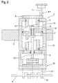
- Fig. 2 shows the crimping device after Fig. 1 in longitudinal section. Only one of the jaws 3.1 and the inserted cable end 4 is shown.
- the gripper jaws 3.1 is designed like a comb and provided with teeth 17 extending transversely to the longitudinal direction. In the gaps of the teeth 17 engage in addition by the other gripper jaws 3.1 whose teeth 17 almost completely. Even very thin and highly flexible cables 4 can thereby be pushed through in the open position of the gripper jaws, in which they have a very small distance A from the cable 4, without any risk of entanglement or jamming in the gaps formed by the spacing of the teeth ,
- Fig. 3 shows schematically reproduced gripper jaws in the open position and with a cable inserted therein in a front view.
- the distance A between the gripper jaws 3.1 and the outer circumference of the cable end 4 is determined empirically and dimensioned so that the cable end 4 in good Leadership can be easily moved. It can be reduced by pushing together the gripper jaws 3.1 and enlarge by a Auseinaderteil.
- Fig. 4 shows a control disc 8 is in engagement with an abutment 11 in plan view.
- the control disk 8 is provided with a parallel to the cylindrical abutment 11 projecting cam 8.1, which is here of rectangular profile.
- Fig. 5 shows a helical stop 5 with a stop surface 5.1 in a perspective view.
- the stop surface 5.1 is formed by a coiled rising annular surface.
- the slope of the annular surface, relative to a horizontal plane, is preferably 2 ° to 5 °.
- the advantage of such a design is that the stop limit can be adjusted continuously, which allows especially for very thin cables, on the one hand to achieve the desired, solid and damage-free grip of the cable 4 in the cable gripper 3 and on the other hand damage to the cable sheath by the cable gripper 3 to avoid.
- the design is therefore preferred.
Landscapes
- Engineering & Computer Science (AREA)
- Manufacturing & Machinery (AREA)
- Manufacturing Of Electrical Connectors (AREA)
Priority Applications (1)
| Application Number | Priority Date | Filing Date | Title |
|---|---|---|---|
| PL09171190T PL2169782T3 (pl) | 2008-09-25 | 2009-09-24 | Urządzenie do obciskania |
Applications Claiming Priority (1)
| Application Number | Priority Date | Filing Date | Title |
|---|---|---|---|
| DE102008049022.9A DE102008049022B4 (de) | 2008-09-25 | 2008-09-25 | Crimpeinrichtung |
Publications (3)
| Publication Number | Publication Date |
|---|---|
| EP2169782A2 EP2169782A2 (de) | 2010-03-31 |
| EP2169782A3 EP2169782A3 (de) | 2013-03-27 |
| EP2169782B1 true EP2169782B1 (de) | 2016-02-17 |
Family
ID=41412428
Family Applications (1)
| Application Number | Title | Priority Date | Filing Date |
|---|---|---|---|
| EP09171190.3A Active EP2169782B1 (de) | 2008-09-25 | 2009-09-24 | Crimpeinrichtung |
Country Status (4)
| Country | Link |
|---|---|
| EP (1) | EP2169782B1 (pl) |
| DE (1) | DE102008049022B4 (pl) |
| ES (1) | ES2570335T3 (pl) |
| PL (1) | PL2169782T3 (pl) |
Family Cites Families (7)
| Publication number | Priority date | Publication date | Assignee | Title |
|---|---|---|---|---|
| US3176550A (en) * | 1963-09-12 | 1965-04-06 | Gen Electric | Wire stripping machine |
| GB1312259A (en) * | 1969-09-30 | 1973-04-04 | Bullick Dobson Ltd | Stroke-limitting means for piston and cylinder devices |
| DE4032765A1 (de) * | 1990-10-16 | 1992-04-23 | Linde Ag | Zylinder-kolben-einheit mit einer vorrichtung zur begrenzung des kolbenhubes |
| JPH0666148B2 (ja) * | 1992-09-01 | 1994-08-24 | 日本オートマチックマシン株式会社 | 電線の2段階クランプ方法 |
| US5331867A (en) * | 1992-10-19 | 1994-07-26 | Carpenter Manufacturing Co., Inc. | Wire insulation cutting and stripping apparatus |
| US6176155B1 (en) * | 1998-09-18 | 2001-01-23 | Schleuniger Holding Ag | Semi-automatic wire processing apparatus |
| EP1548903B1 (de) * | 2003-12-22 | 2007-09-19 | komax Holding AG | Kabelbearbeitungseinrichtung |
-
2008
- 2008-09-25 DE DE102008049022.9A patent/DE102008049022B4/de not_active Expired - Fee Related
-
2009
- 2009-09-24 PL PL09171190T patent/PL2169782T3/pl unknown
- 2009-09-24 ES ES09171190T patent/ES2570335T3/es active Active
- 2009-09-24 EP EP09171190.3A patent/EP2169782B1/de active Active
Also Published As
| Publication number | Publication date |
|---|---|
| DE102008049022B4 (de) | 2014-02-20 |
| DE102008049022A1 (de) | 2010-04-08 |
| EP2169782A2 (de) | 2010-03-31 |
| EP2169782A3 (de) | 2013-03-27 |
| PL2169782T3 (pl) | 2016-08-31 |
| ES2570335T3 (es) | 2016-05-17 |
Similar Documents
| Publication | Publication Date | Title |
|---|---|---|
| DE4207576C2 (de) | Greif- und Zuführvorrichtung | |
| DE102019129976A1 (de) | Werkzeugwechselvorrichtung eines Werkzeugmagazins | |
| DE102012224045A1 (de) | Schraubsystem | |
| EP0546382B1 (de) | Handnietgerät | |
| EP2897744A1 (de) | Vorrichtung und verfahren zum automatischen verdrillen von metalldrähten, insbesondere zum verbinden benachbarter, vorzugweise sich überkreuzender strukturelemente | |
| DE2426072C2 (de) | Vorrichtung zum Bohren und Aushalsen der Wandung eines Rohres | |
| DE4132998C2 (de) | Ansaug- und Transportvorrichtung | |
| DE19817882A1 (de) | Radialpresse | |
| DE3605099A1 (de) | Vorrichtung zum auswechseln der elektrodenkappen einer roboter-punktschweisszange | |
| DE19724635C2 (de) | Werkzeugmaschine mit Werkzeugauswechselvorrichtung | |
| EP0462923A2 (de) | Vorrichtung zum Aufbringen von weichelastischen Dichtungs- Tüllen auf elektrische Leitungsenden | |
| EP3720615B1 (de) | Vorrichtung zum auftragen eines viskosen materials auf werkstücke | |
| EP2169782B1 (de) | Crimpeinrichtung | |
| EP1956691B1 (de) | Kabelbearbeitungseinrichtung mit mehreren Bearbeitungsstationen zur Konfektionierung eines Kabels | |
| DE19637686C1 (de) | Vorrichtung und Arbeitsverfahren zum Einfädeln von Rohren oder Stangen in ein Ziehaggregat | |
| DE2705794C2 (de) | Übergabevorrichtung | |
| DE9206410U1 (de) | Spritzvorrichtung für die Innenwände von Hohlkörpern | |
| DE19506336A1 (de) | An eine Antriebseinheit anbaubare Vorrichtung zum Eindrehen von Schrauben | |
| EP1879199A2 (de) | Vorrichtung zur wahlweisen Zuführung von einem von zwei Kabeln zu einem von zwei antreibbaren Reibrollen gebildeten Spalt | |
| DE3508354C2 (de) | Maschine zum Aufquetschbestücken von Kabeladerenden mit Aderendhülsen od.dgl. Anschlußelementen | |
| EP1430985A1 (de) | Schweisszange umfassend einen programmierbaren Linearantrieb mit zwei unabhängigen Regelkreisen sowie Verfahren zur Ansteuerung des Linearantriebs solcher Schweisszange | |
| DE10212993A1 (de) | Crimp-Verfahren | |
| DE102007019269A1 (de) | Kabelbearbeitungseinrichtung | |
| DE19940474B4 (de) | Vorrichtung und Verfahren zur Verlegung von Kabeln in Rohren | |
| EP0564445A1 (de) | Vorrichtung zum alternativen Zuführen von Material zu einer Verarbeitungsanlage |
Legal Events
| Date | Code | Title | Description |
|---|---|---|---|
| PUAI | Public reference made under article 153(3) epc to a published international application that has entered the european phase |
Free format text: ORIGINAL CODE: 0009012 |
|
| AK | Designated contracting states |
Kind code of ref document: A2 Designated state(s): AT BE BG CH CY CZ DE DK EE ES FI FR GB GR HR HU IE IS IT LI LT LU LV MC MK MT NL NO PL PT RO SE SI SK SM TR |
|
| AX | Request for extension of the european patent |
Extension state: AL BA RS |
|
| PUAL | Search report despatched |
Free format text: ORIGINAL CODE: 0009013 |
|
| AK | Designated contracting states |
Kind code of ref document: A3 Designated state(s): AT BE BG CH CY CZ DE DK EE ES FI FR GB GR HR HU IE IS IT LI LT LU LV MC MK MT NL NO PL PT RO SE SI SK SM TR |
|
| AX | Request for extension of the european patent |
Extension state: AL BA RS |
|
| RIC1 | Information provided on ipc code assigned before grant |
Ipc: H01R 43/048 20060101AFI20130219BHEP |
|
| RAP1 | Party data changed (applicant data changed or rights of an application transferred) |
Owner name: SCHAEFER WERKZEUG- UND SONDERMASCHINENBAU GMBH |
|
| 17P | Request for examination filed |
Effective date: 20130924 |
|
| RBV | Designated contracting states (corrected) |
Designated state(s): AT BE BG CH CY CZ DE DK EE ES FI FR GB GR HR HU IE IS IT LI LT LU LV MC MK MT NL NO PL PT RO SE SI SK SM TR |
|
| GRAP | Despatch of communication of intention to grant a patent |
Free format text: ORIGINAL CODE: EPIDOSNIGR1 |
|
| INTG | Intention to grant announced |
Effective date: 20150807 |
|
| GRAS | Grant fee paid |
Free format text: ORIGINAL CODE: EPIDOSNIGR3 |
|
| GRAA | (expected) grant |
Free format text: ORIGINAL CODE: 0009210 |
|
| AK | Designated contracting states |
Kind code of ref document: B1 Designated state(s): AT BE BG CH CY CZ DE DK EE ES FI FR GB GR HR HU IE IS IT LI LT LU LV MC MK MT NL NO PL PT RO SE SI SK SM TR |
|
| REG | Reference to a national code |
Ref country code: GB Ref legal event code: FG4D Free format text: NOT ENGLISH |
|
| REG | Reference to a national code |
Ref country code: CH Ref legal event code: NV Representative=s name: SCHNEIDER FELDMANN AG PATENT- UND MARKENANWAEL, CH Ref country code: CH Ref legal event code: EP |
|
| REG | Reference to a national code |
Ref country code: IE Ref legal event code: FG4D Free format text: LANGUAGE OF EP DOCUMENT: GERMAN |
|
| REG | Reference to a national code |
Ref country code: AT Ref legal event code: REF Ref document number: 776021 Country of ref document: AT Kind code of ref document: T Effective date: 20160315 |
|
| REG | Reference to a national code |
Ref country code: DE Ref legal event code: R096 Ref document number: 502009012141 Country of ref document: DE |
|
| REG | Reference to a national code |
Ref country code: RO Ref legal event code: EPE |
|
| REG | Reference to a national code |
Ref country code: ES Ref legal event code: FG2A Ref document number: 2570335 Country of ref document: ES Kind code of ref document: T3 Effective date: 20160517 |
|
| REG | Reference to a national code |
Ref country code: NL Ref legal event code: MP Effective date: 20160217 |
|
| REG | Reference to a national code |
Ref country code: LT Ref legal event code: MG4D |
|
| PG25 | Lapsed in a contracting state [announced via postgrant information from national office to epo] |
Ref country code: FI Free format text: LAPSE BECAUSE OF FAILURE TO SUBMIT A TRANSLATION OF THE DESCRIPTION OR TO PAY THE FEE WITHIN THE PRESCRIBED TIME-LIMIT Effective date: 20160217 Ref country code: NO Free format text: LAPSE BECAUSE OF FAILURE TO SUBMIT A TRANSLATION OF THE DESCRIPTION OR TO PAY THE FEE WITHIN THE PRESCRIBED TIME-LIMIT Effective date: 20160517 Ref country code: GR Free format text: LAPSE BECAUSE OF FAILURE TO SUBMIT A TRANSLATION OF THE DESCRIPTION OR TO PAY THE FEE WITHIN THE PRESCRIBED TIME-LIMIT Effective date: 20160518 |
|
| PG25 | Lapsed in a contracting state [announced via postgrant information from national office to epo] |
Ref country code: LV Free format text: LAPSE BECAUSE OF FAILURE TO SUBMIT A TRANSLATION OF THE DESCRIPTION OR TO PAY THE FEE WITHIN THE PRESCRIBED TIME-LIMIT Effective date: 20160217 Ref country code: SE Free format text: LAPSE BECAUSE OF FAILURE TO SUBMIT A TRANSLATION OF THE DESCRIPTION OR TO PAY THE FEE WITHIN THE PRESCRIBED TIME-LIMIT Effective date: 20160217 Ref country code: NL Free format text: LAPSE BECAUSE OF FAILURE TO SUBMIT A TRANSLATION OF THE DESCRIPTION OR TO PAY THE FEE WITHIN THE PRESCRIBED TIME-LIMIT Effective date: 20160217 Ref country code: LT Free format text: LAPSE BECAUSE OF FAILURE TO SUBMIT A TRANSLATION OF THE DESCRIPTION OR TO PAY THE FEE WITHIN THE PRESCRIBED TIME-LIMIT Effective date: 20160217 Ref country code: PT Free format text: LAPSE BECAUSE OF FAILURE TO SUBMIT A TRANSLATION OF THE DESCRIPTION OR TO PAY THE FEE WITHIN THE PRESCRIBED TIME-LIMIT Effective date: 20160617 |
|
| REG | Reference to a national code |
Ref country code: FR Ref legal event code: PLFP Year of fee payment: 8 |
|
| PG25 | Lapsed in a contracting state [announced via postgrant information from national office to epo] |
Ref country code: EE Free format text: LAPSE BECAUSE OF FAILURE TO SUBMIT A TRANSLATION OF THE DESCRIPTION OR TO PAY THE FEE WITHIN THE PRESCRIBED TIME-LIMIT Effective date: 20160217 Ref country code: DK Free format text: LAPSE BECAUSE OF FAILURE TO SUBMIT A TRANSLATION OF THE DESCRIPTION OR TO PAY THE FEE WITHIN THE PRESCRIBED TIME-LIMIT Effective date: 20160217 |
|
| REG | Reference to a national code |
Ref country code: DE Ref legal event code: R097 Ref document number: 502009012141 Country of ref document: DE |
|
| PG25 | Lapsed in a contracting state [announced via postgrant information from national office to epo] |
Ref country code: SM Free format text: LAPSE BECAUSE OF FAILURE TO SUBMIT A TRANSLATION OF THE DESCRIPTION OR TO PAY THE FEE WITHIN THE PRESCRIBED TIME-LIMIT Effective date: 20160217 Ref country code: CZ Free format text: LAPSE BECAUSE OF FAILURE TO SUBMIT A TRANSLATION OF THE DESCRIPTION OR TO PAY THE FEE WITHIN THE PRESCRIBED TIME-LIMIT Effective date: 20160217 Ref country code: SK Free format text: LAPSE BECAUSE OF FAILURE TO SUBMIT A TRANSLATION OF THE DESCRIPTION OR TO PAY THE FEE WITHIN THE PRESCRIBED TIME-LIMIT Effective date: 20160217 |
|
| PLBE | No opposition filed within time limit |
Free format text: ORIGINAL CODE: 0009261 |
|
| STAA | Information on the status of an ep patent application or granted ep patent |
Free format text: STATUS: NO OPPOSITION FILED WITHIN TIME LIMIT |
|
| 26N | No opposition filed |
Effective date: 20161118 |
|
| PG25 | Lapsed in a contracting state [announced via postgrant information from national office to epo] |
Ref country code: BE Free format text: LAPSE BECAUSE OF NON-PAYMENT OF DUE FEES Effective date: 20160930 Ref country code: BG Free format text: LAPSE BECAUSE OF FAILURE TO SUBMIT A TRANSLATION OF THE DESCRIPTION OR TO PAY THE FEE WITHIN THE PRESCRIBED TIME-LIMIT Effective date: 20160517 Ref country code: SI Free format text: LAPSE BECAUSE OF FAILURE TO SUBMIT A TRANSLATION OF THE DESCRIPTION OR TO PAY THE FEE WITHIN THE PRESCRIBED TIME-LIMIT Effective date: 20160217 |
|
| PG25 | Lapsed in a contracting state [announced via postgrant information from national office to epo] |
Ref country code: MC Free format text: LAPSE BECAUSE OF FAILURE TO SUBMIT A TRANSLATION OF THE DESCRIPTION OR TO PAY THE FEE WITHIN THE PRESCRIBED TIME-LIMIT Effective date: 20160217 |
|
| REG | Reference to a national code |
Ref country code: IE Ref legal event code: MM4A |
|
| PG25 | Lapsed in a contracting state [announced via postgrant information from national office to epo] |
Ref country code: IE Free format text: LAPSE BECAUSE OF NON-PAYMENT OF DUE FEES Effective date: 20160924 |
|
| PG25 | Lapsed in a contracting state [announced via postgrant information from national office to epo] |
Ref country code: LU Free format text: LAPSE BECAUSE OF NON-PAYMENT OF DUE FEES Effective date: 20160924 |
|
| REG | Reference to a national code |
Ref country code: FR Ref legal event code: PLFP Year of fee payment: 9 |
|
| REG | Reference to a national code |
Ref country code: AT Ref legal event code: MM01 Ref document number: 776021 Country of ref document: AT Kind code of ref document: T Effective date: 20160924 |
|
| REG | Reference to a national code |
Ref country code: BE Ref legal event code: MM Effective date: 20160930 |
|
| PG25 | Lapsed in a contracting state [announced via postgrant information from national office to epo] |
Ref country code: AT Free format text: LAPSE BECAUSE OF NON-PAYMENT OF DUE FEES Effective date: 20160924 |
|
| PG25 | Lapsed in a contracting state [announced via postgrant information from national office to epo] |
Ref country code: HU Free format text: LAPSE BECAUSE OF FAILURE TO SUBMIT A TRANSLATION OF THE DESCRIPTION OR TO PAY THE FEE WITHIN THE PRESCRIBED TIME-LIMIT; INVALID AB INITIO Effective date: 20090924 Ref country code: CY Free format text: LAPSE BECAUSE OF FAILURE TO SUBMIT A TRANSLATION OF THE DESCRIPTION OR TO PAY THE FEE WITHIN THE PRESCRIBED TIME-LIMIT Effective date: 20160217 |
|
| PG25 | Lapsed in a contracting state [announced via postgrant information from national office to epo] |
Ref country code: MT Free format text: LAPSE BECAUSE OF FAILURE TO SUBMIT A TRANSLATION OF THE DESCRIPTION OR TO PAY THE FEE WITHIN THE PRESCRIBED TIME-LIMIT Effective date: 20160217 Ref country code: HR Free format text: LAPSE BECAUSE OF FAILURE TO SUBMIT A TRANSLATION OF THE DESCRIPTION OR TO PAY THE FEE WITHIN THE PRESCRIBED TIME-LIMIT Effective date: 20160217 Ref country code: MK Free format text: LAPSE BECAUSE OF FAILURE TO SUBMIT A TRANSLATION OF THE DESCRIPTION OR TO PAY THE FEE WITHIN THE PRESCRIBED TIME-LIMIT Effective date: 20160217 Ref country code: IS Free format text: LAPSE BECAUSE OF FAILURE TO SUBMIT A TRANSLATION OF THE DESCRIPTION OR TO PAY THE FEE WITHIN THE PRESCRIBED TIME-LIMIT Effective date: 20160217 Ref country code: TR Free format text: LAPSE BECAUSE OF FAILURE TO SUBMIT A TRANSLATION OF THE DESCRIPTION OR TO PAY THE FEE WITHIN THE PRESCRIBED TIME-LIMIT Effective date: 20160217 |
|
| REG | Reference to a national code |
Ref country code: FR Ref legal event code: PLFP Year of fee payment: 10 |
|
| PGFP | Annual fee paid to national office [announced via postgrant information from national office to epo] |
Ref country code: GB Payment date: 20190830 Year of fee payment: 11 |
|
| PGFP | Annual fee paid to national office [announced via postgrant information from national office to epo] |
Ref country code: ES Payment date: 20191007 Year of fee payment: 11 |
|
| REG | Reference to a national code |
Ref country code: CH Ref legal event code: PFA Owner name: SCHAEFER WERKZEUG- UND SONDERMASCHINENBAU GMBH, DE Free format text: FORMER OWNER: SCHAEFER WERKZEUG- UND SONDERMASCHINENBAU GMBH, DE |
|
| GBPC | Gb: european patent ceased through non-payment of renewal fee |
Effective date: 20200924 |
|
| PG25 | Lapsed in a contracting state [announced via postgrant information from national office to epo] |
Ref country code: GB Free format text: LAPSE BECAUSE OF NON-PAYMENT OF DUE FEES Effective date: 20200924 |
|
| REG | Reference to a national code |
Ref country code: ES Ref legal event code: FD2A Effective date: 20220119 |
|
| PG25 | Lapsed in a contracting state [announced via postgrant information from national office to epo] |
Ref country code: ES Free format text: LAPSE BECAUSE OF NON-PAYMENT OF DUE FEES Effective date: 20200925 |
|
| REG | Reference to a national code |
Ref country code: CH Ref legal event code: U11 Free format text: ST27 STATUS EVENT CODE: U-0-0-U10-U11 (AS PROVIDED BY THE NATIONAL OFFICE) Effective date: 20251001 |
|
| PGFP | Annual fee paid to national office [announced via postgrant information from national office to epo] |
Ref country code: DE Payment date: 20250925 Year of fee payment: 17 |
|
| PGFP | Annual fee paid to national office [announced via postgrant information from national office to epo] |
Ref country code: IT Payment date: 20250926 Year of fee payment: 17 Ref country code: PL Payment date: 20250808 Year of fee payment: 17 |
|
| PGFP | Annual fee paid to national office [announced via postgrant information from national office to epo] |
Ref country code: FR Payment date: 20250926 Year of fee payment: 17 |
|
| PGFP | Annual fee paid to national office [announced via postgrant information from national office to epo] |
Ref country code: RO Payment date: 20250917 Year of fee payment: 17 |
|
| PGFP | Annual fee paid to national office [announced via postgrant information from national office to epo] |
Ref country code: CH Payment date: 20251001 Year of fee payment: 17 |