EP2170452B1 - Cathéter à ballonnet avec mécanisme de dégonflage - Google Patents
Cathéter à ballonnet avec mécanisme de dégonflage Download PDFInfo
- Publication number
- EP2170452B1 EP2170452B1 EP08781427A EP08781427A EP2170452B1 EP 2170452 B1 EP2170452 B1 EP 2170452B1 EP 08781427 A EP08781427 A EP 08781427A EP 08781427 A EP08781427 A EP 08781427A EP 2170452 B1 EP2170452 B1 EP 2170452B1
- Authority
- EP
- European Patent Office
- Prior art keywords
- balloon
- distal end
- catheter
- stiffening member
- tubular member
- Prior art date
- Legal status (The legal status is an assumption and is not a legal conclusion. Google has not performed a legal analysis and makes no representation as to the accuracy of the status listed.)
- Active
Links
Images
Classifications
-
- A—HUMAN NECESSITIES
- A61—MEDICAL OR VETERINARY SCIENCE; HYGIENE
- A61M—DEVICES FOR INTRODUCING MEDIA INTO, OR ONTO, THE BODY; DEVICES FOR TRANSDUCING BODY MEDIA OR FOR TAKING MEDIA FROM THE BODY; DEVICES FOR PRODUCING OR ENDING SLEEP OR STUPOR
- A61M25/00—Catheters; Hollow probes
- A61M25/10—Balloon catheters
- A61M25/1027—Making of balloon catheters
-
- A—HUMAN NECESSITIES
- A61—MEDICAL OR VETERINARY SCIENCE; HYGIENE
- A61M—DEVICES FOR INTRODUCING MEDIA INTO, OR ONTO, THE BODY; DEVICES FOR TRANSDUCING BODY MEDIA OR FOR TAKING MEDIA FROM THE BODY; DEVICES FOR PRODUCING OR ENDING SLEEP OR STUPOR
- A61M25/00—Catheters; Hollow probes
- A61M25/10—Balloon catheters
- A61M25/1002—Balloon catheters characterised by balloon shape
- A61M2025/1004—Balloons with folds, e.g. folded or multifolded
-
- A—HUMAN NECESSITIES
- A61—MEDICAL OR VETERINARY SCIENCE; HYGIENE
- A61M—DEVICES FOR INTRODUCING MEDIA INTO, OR ONTO, THE BODY; DEVICES FOR TRANSDUCING BODY MEDIA OR FOR TAKING MEDIA FROM THE BODY; DEVICES FOR PRODUCING OR ENDING SLEEP OR STUPOR
- A61M25/00—Catheters; Hollow probes
- A61M25/10—Balloon catheters
- A61M2025/1043—Balloon catheters with special features or adapted for special applications
- A61M2025/1052—Balloon catheters with special features or adapted for special applications for temporarily occluding a vessel for isolating a sector
-
- A—HUMAN NECESSITIES
- A61—MEDICAL OR VETERINARY SCIENCE; HYGIENE
- A61M—DEVICES FOR INTRODUCING MEDIA INTO, OR ONTO, THE BODY; DEVICES FOR TRANSDUCING BODY MEDIA OR FOR TAKING MEDIA FROM THE BODY; DEVICES FOR PRODUCING OR ENDING SLEEP OR STUPOR
- A61M25/00—Catheters; Hollow probes
- A61M25/10—Balloon catheters
- A61M2025/1043—Balloon catheters with special features or adapted for special applications
- A61M2025/1061—Balloon catheters with special features or adapted for special applications having separate inflations tubes, e.g. coaxial tubes or tubes otherwise arranged apart from the catheter tube
-
- A—HUMAN NECESSITIES
- A61—MEDICAL OR VETERINARY SCIENCE; HYGIENE
- A61M—DEVICES FOR INTRODUCING MEDIA INTO, OR ONTO, THE BODY; DEVICES FOR TRANSDUCING BODY MEDIA OR FOR TAKING MEDIA FROM THE BODY; DEVICES FOR PRODUCING OR ENDING SLEEP OR STUPOR
- A61M25/00—Catheters; Hollow probes
- A61M25/10—Balloon catheters
- A61M2025/1043—Balloon catheters with special features or adapted for special applications
- A61M2025/1093—Balloon catheters with special features or adapted for special applications having particular tip characteristics
-
- A—HUMAN NECESSITIES
- A61—MEDICAL OR VETERINARY SCIENCE; HYGIENE
- A61M—DEVICES FOR INTRODUCING MEDIA INTO, OR ONTO, THE BODY; DEVICES FOR TRANSDUCING BODY MEDIA OR FOR TAKING MEDIA FROM THE BODY; DEVICES FOR PRODUCING OR ENDING SLEEP OR STUPOR
- A61M25/00—Catheters; Hollow probes
- A61M25/0067—Catheters; Hollow probes characterised by the distal end, e.g. tips
- A61M25/0068—Static characteristics of the catheter tip, e.g. shape, atraumatic tip, curved tip or tip structure
- A61M25/0069—Tip not integral with tube
-
- A—HUMAN NECESSITIES
- A61—MEDICAL OR VETERINARY SCIENCE; HYGIENE
- A61M—DEVICES FOR INTRODUCING MEDIA INTO, OR ONTO, THE BODY; DEVICES FOR TRANSDUCING BODY MEDIA OR FOR TAKING MEDIA FROM THE BODY; DEVICES FOR PRODUCING OR ENDING SLEEP OR STUPOR
- A61M25/00—Catheters; Hollow probes
- A61M25/0067—Catheters; Hollow probes characterised by the distal end, e.g. tips
- A61M25/0068—Static characteristics of the catheter tip, e.g. shape, atraumatic tip, curved tip or tip structure
- A61M25/007—Side holes, e.g. their profiles or arrangements; Provisions to keep side holes unblocked
-
- A—HUMAN NECESSITIES
- A61—MEDICAL OR VETERINARY SCIENCE; HYGIENE
- A61M—DEVICES FOR INTRODUCING MEDIA INTO, OR ONTO, THE BODY; DEVICES FOR TRANSDUCING BODY MEDIA OR FOR TAKING MEDIA FROM THE BODY; DEVICES FOR PRODUCING OR ENDING SLEEP OR STUPOR
- A61M25/00—Catheters; Hollow probes
- A61M25/10—Balloon catheters
- A61M25/1025—Connections between catheter tubes and inflation tubes
-
- A—HUMAN NECESSITIES
- A61—MEDICAL OR VETERINARY SCIENCE; HYGIENE
- A61M—DEVICES FOR INTRODUCING MEDIA INTO, OR ONTO, THE BODY; DEVICES FOR TRANSDUCING BODY MEDIA OR FOR TAKING MEDIA FROM THE BODY; DEVICES FOR PRODUCING OR ENDING SLEEP OR STUPOR
- A61M25/00—Catheters; Hollow probes
- A61M25/10—Balloon catheters
- A61M25/1027—Making of balloon catheters
- A61M25/1034—Joining of shaft and balloon
Definitions
- This invention relates to medical devices, and more particularly to balloon catheters that can be placed within a body lumen and inflated to perform various medical procedures.
- the invention is especially relevant to balloon catheters with balloons formed of non-elastomeric films or materials, wherein the film that forms the balloon is folded and unfolded during deflation and inflation, respectively, of the balloon.
- Balloon catheters are used to perform various medical procedures wherein the balloon is positioned within a body lumen or canal and subsequently inflated.
- the balloon is inflated so as to expand the interior volume of the body canal.
- the balloon is expanded to apply pressure to the interior surface of the body canal to thereby compress any tissue protruding into the canal and thereby enlarge the interior volume thereof. Once the tissue has been compressed, and the body canal widened, the balloon is deflated and removed.
- Document US 2004/0236366 A1 describes a balloon catheter including an inflatable balloon affixed to a catheter.
- the proximal end of the balloon is affixed to the distal end of the catheter so as to provide an air tight seal there between.
- a stiffening member extends distally of the distal end of the catheter and forms a slip joint connection with the distal end of the balloon to permit the distal end of the balloon to axially move or translate relative to the distal end of the catheter.
- the slip joint allows the axial length of balloon to change during inflation or deflation without transferring tensile or compressive forces between the balloon and the catheter, thereby preventing transverse creases from forming in the surface of the balloon and preventing the catheter from bowing.
- the stiffening member provides alignment and lateral support to the distal end of the balloon.
- Document WO 2007/054364 A2 describes a catheter comprising an outer tube; an inner tube; and a balloon fixed at its proximal sleeve to the outer tube and at its distal sleeve to the inner tube, wherein the inner tube comprises an elastic segment.
- a balloon catheter is used to align and stabilize the catheter within the body lumen.
- the balloon catheter may be inflated under low pressure within a body lumen such as the esophagus.
- a therapeutic fiber optic device is then inserted into the catheter in the vicinity of the balloon.
- the therapeutic fiber optic device is then used to emit light waves to treat the surrounding tissue.
- the balloon is used to both align the catheter in the center of the body lumen, and to prevent the catheter from moving during the PDT procedure.
- the balloon of a typical PDT balloon catheter is relatively large as compared to balloon catheters for use in angioplasty procedures.
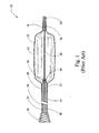
- the balloon catheter 10 comprises a balloon 12 that is affixed to a catheter 14.
- the balloon 12 is typically manufactured from a non-elastomeric material (e.g., a semi-rigid or non-compliant material), and includes a distal neck or end 16, a proximal neck or end 18 and a central portion 20.
- the proximal end 18 of the balloon 12 is secured and sealed to the distal end 22 of the catheter 14 by an adhesive, ultrasonic welding, or some other method.
- the distal end 16 of the balloon 12 is similarly secured and sealed to an end cap 24 by an adhesive, ultrasonic welding, or some other method.
- the end cap 24 is affixed to the distal end 26 of a stiffening wire 28, which projects distally from the distal end 22 of the catheter 14.
- the proximal end 30 of the stiffening wire 28 is secured to a hub 32, which in turn is attached to the proximal end 34 of the catheter 14.
- the stiffening wire 28 provides lateral and longitudinal support to the distal end 16 of the balloon 12, while also providing a cross-sectional profile that is smaller than that of the catheter 14. This allows the balloon 12 to be folded or collapsed into a smaller profile for passage into and out of the patient.
- the hub 32 is configured to be attached to a device, such as a syringe (not shown), that may be manipulated to either inflate or deflate the balloon 12 by injecting a fluid into or withdrawing a fluid from, respectively, the interior volume of the balloon 12.
- a device such as a syringe (not shown)
- the balloon 12 is inflated by injecting a fluid such as saline through the hub 32 and into the inflation lumen 38 of the catheter 14.
- the fluid passes through the inflation lumen 38 and into the interior volume of the balloon 12 via one or more apertures 36 in the distal end 22 of the catheter 14.
- the balloon 12 is deflated by withdrawing the fluid from the interior volume of the balloon 12 via the apertures 36 and the inflation lumen 38 of the catheter 14.
- Conventional balloon catheters for use in the above-described procedures have several drawbacks.
- One such drawback is that conventional balloon catheters often require an inordinate amount of time to be deflated, which must be completely deflated before the balloon can be withdrawn from the patient. This can unnecessarily increase the duration of the procedure, with obvious negative consequences to the patient.
- Another drawback of conventional balloon catheters is that sometimes the balloon will not deflate completely. When this occurs, it may be difficult or impossible to withdraw the balloon from the patient, particularly when the balloon catheter has been introduced into the patient through an endoscope or other introducer device.
- Balloon catheters for use in PDT procedures which have relatively large volume balloons, are particularly susceptible to the above-described problems.
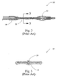
- Figs. 2-3 illustrate the conventional balloon catheter 10 of Fig. 1 that will not deflate completely.
- the interior surface of the balloon 12 as shown in Fig. 2 , as the balloon 12 begins to deflate, the interior surface of the balloon 12 as been drawn inwardly and into contact with the exterior surface of the stiffening wire 28. As further suction is applied to the balloon 12 (via inflation lumen 38), the proximal portion of the balloon 12 completely collapses about the stiffening wire 28, as illustrated in Fig. 3 . Once the interior surface of the balloon 12 seals about the stiffening wire 28, any inflation fluid remaining within the distal portion of the balloon 12 becomes trapped within the balloon 12. Any further application of suction merely increases the seal between the interior surface of the balloon 12 and the stiffening wire 28, and will not result in egress of the fluid remaining in the balloon 12.
- What is needed is an improved balloon catheter that overcomes the disadvantages of the conventional device.
- a balloon catheter that can be quickly and completely deflated to a minimal diameter for ingress and egress through the body's canals and/or an endoscope channel.
- FIG. 1 depicts cross-sectional side view of a conventional balloon catheter in the inflated state
- FIG. 2 depicts a cross-sectional side view of the distal portion of the balloon catheter of FIG. 1 in a partially deflated state
- FIG. 3 is sectional view taken along line 3--3 of FIG. 2 ;
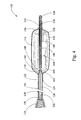
- FIG. 4 depicts a cross-sectional side view of an illustrative example of a balloon catheter in accordance with the teachings of the present invention
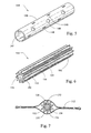
- FIG. 5 is a perspective view of the deflation mechanism utilized in the balloon catheter of FIG. 4 ;
- FIG. 6 is a perspective view of an alternative embodiment of a deflation mechanism that may be utilized in the balloon catheter of FIG. 4 ;
- FIG. 7 is a cross-sectional view of the deflation mechanism of FIG. 6 disposed within a partially deflated balloon.
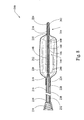
- FIG. 8 is a cross-sectional side view of the embodiment of a balloon catheter in accordance with the teachings of the present invention.
- the balloon catheter 110 includes a rounded, oval, cylindrical, bullet or other appropriately shaped balloon 112 that is affixed to a catheter 114.
- the balloon 112 is typically manufactured from a non-elastomeric material (e.g., a semi-rigid or non-compliant material), and preferably comprises a translucent, transparent or optically clear film.
- the balloon 112 could be manufactured from a biocompatible polymer such as polyamide, polyurethane, polyester, polyolefin, polyethylene terephthalate and the like.
- the balloon 112 includes a conically shaped distal portion 116, a conically shaped proximal portion 118 and a cylindrically shaped central portion 120.
- the distal and proximal portions 116, 118 could comprise a curvilinear shape.
- the proximal and distal ends of the balloon 112 further comprise cylindrical neck portions 122, which provide a mechanism for securing and sealing the balloon 112 to other components of the balloon catheter 110 (i.e., to catheter 114 and end cap 126).
- the central portion 120 of the balloon 112 may be provided with longitudinally or axially extending pleats or folds (not shown). These folds provide creases along which the surface of the balloon 112 will fold or pleat when deflated. The folds permit the central portion 120 of the balloon 112 to be collapsed to a minimal cross-sectional area or diameter, and prevent the formation of transverse or lateral creases along the same area.
- the proximal end of the balloon 112 is attached to the catheter 114 by inserting the distal end 124 of the catheter 114 into the neck portion 122 attached to the proximal end of the balloon 112.
- the neck portion 122 is then affixed to the outer wall of the catheter 114 by an adhesive, ultrasonic welding, or some other method so as to anchor and seal the proximal end of the balloon 112 thereto.
- the inside diameter of the neck portion 122 is sized to fit tightly or snugly over the catheter 114 so as to improve the integrity of the seal between these two components.
- the distal end of the balloon 112 is attached to an end cap 126, which encloses and seals the distal end of the balloon 112.
- the distal end of the balloon 112 is attached to an end cap 126 by inserting the proximal end of the end cap 126 into the neck portion 122 attached to the proximal end of the balloon 112.
- the neck portion 122 is then affixed to the outer wall of the end cap 126 by an adhesive, ultrasonic welding, or some other method so as to anchor and seal the distal end of the balloon 112 thereto.
- the inside diameter of the neck portion 122 is sized to fit tightly or snugly over the end cap 126 so as to improve the integrity of the seal between these two components.
- the distal end of the end cap 126 is preferably rounded to facilitate advancement of the balloon catheter 110 through the bodily lumens of the patient.
- the distal end of the end cap 126 may also be tapered and/or made from a flexible material.
- a stiffening wire (mandrel) 128 projects distally from the distal end 124 of the catheter 114 and traverses the interior of the balloon 112.
- the distal end 130 of the stiffening wire 128 is fixedly connected to the end cap 126, and provides longitudinal and lateral support to the distal end of the balloon 112.
- the diameter of the stiffening wire 128 is smaller than that of the catheter 114, thereby allowing the balloon 112 to be folded into a smaller cross-sectional area than would be possible if the catheter 114 extended through the interior of the balloon 112.
- the cross-section area of the collapsed and folded balloon 112 is not substantially larger than the cross-sectional area of the catheter 114.
- the stiffening wire 128 extends proximally through the catheter 114 and is attached at its proximal end 132 to a hub 134, which in turn is connected to the proximal end 136 of the catheter 114.
- the stiffening wire 128 passes through the inflation lumen 138 of the catheter 114.
- the stiffening wire 128 may be disposed in a separate lumen of the catheter 114.
- the catheter 114 may also comprise additional lumens through which contrast fluids or guide wires (not shown) can be passed.
- the hub 134 is configured for attachment to an inflation device, such as a standard medical syringe (not shown), for providing an inflation fluid to inflate the balloon 112. More specifically, an inflation fluid, such as saline, is injected though the hub 134 and into the lumen 138. The inflation fluid then passes through the lumen 138 and into the interior of the balloon 112 via one or more apertures 140 provided in the distal end 124 of the catheter 114. The balloon 112 is deflated by withdrawing the inflation fluid from the interior of the balloon 112 via the apertures 140, lumen 138 and hub 134.
- the apertures 140 are disposed in a tapered insert 142 that is press fit into or otherwise secured to the distal end 124 of the catheter 114.
- the tapered shape of the insert 142 is configured to prevent the apertures 140 from being occluded by the balloon 112 as it is being deflated.
- a deflation mechanism 144 is disposed about the portion of the stiffening wire 128 that traverses the interior of the balloon 112. As will be explained in detail below, the deflation mechanism 144 is configured to facilitate the passage of inflation fluid towards the apertures 140 at the distal end 124 of the catheter 114 during deflation of the balloon 112.
- the deflation mechanism 144 comprises a tubular member 146 having a circular or cylindrical cross-section with a central passageway 147 longitudinally extending therethrough.
- the inside diameter of the tubular member 146 (i.e., the diameter of passageway 147) is sufficiently large, relative to the outside diameter of the stiffening wire 128, to permit the flow of inflation fluid through and along the interior of the tubular member 146 (i.e., through passageway 147).
- the outside diameter of the tubular member 146 is preferably smaller than the outside diameter of the catheter 114, thereby providing space for the collapsed and folded balloon 112 thereabout.
- the tubular member 146 has an outside diameter of about 14,73 mm (0.58 inches) and an inside diameter of about 11,43 mm (0.45 inches).
- the outside diameter of the stiffening wire 128 is about 6,60-6,85mm (0.26-0.27 inches).
- the inside diameter of the tubular member 146 could be provided with grooves or flow channels through which the inflation fluid will flow, thereby minimizing or eliminating the need for a gap between the inside of the tubular member 146 and the outside of the stiffening wire 128. Such an arrangement may allow the use of a smaller diameter tubular member 146.
- the tubular member 146 also comprises a plurality of openings 148 disposed circumferentially and longitudinally therealong.
- the openings 148 provide a means for egress of any inflation fluid trapped within a portion of the balloon 112 during deflation. More specifically, any fluid trapped within a portion of the balloon 112 will pass through the openings 148 and into the interior of the tubular member 146, whereby the fluid can be directed (flow) towards the apertures 140 in the distal end 124 of the catheter 114, even if a portion of the balloon 112 has collapsed and sealed against a portion of the stiffening wire 128 and/or the tubular member 146. As best seen in FIG.
- the openings 148 are disposed circumferentially about the tubular member 146 in a spiral pattern.
- other patterns or arrangements for the openings 148 can be utilized so long as the distance between any portion of the balloon 112 and at least one opening 148 is kept to a minimum.
- tubular member 146 has a length that is slightly shorter than the length of the portion of the stiffening wire 128 that traverses the interior of the balloon 112. In other words, the tubular member 146 has a length that is less than the distance between the distal face of the insert 142 and the proximal face of the end cap 126. This allows the tubular member 146 to "float" on the stiffening wire 128, which prevents the tubular member from interfering with the stiffening/centering function of the stiffening wire 128, or the shape of the balloon 112 as it is inflated or deflated.
- the length of the tubular member is 1-2 mm less than the distance between the distal face of the insert 142 and the proximal face of the end cap 126.
- the ends of tubular member 146 may be scalloped to facilitate passage of inflation fluid at the ends thereof.
- the tubular member 146 is preferably made from relatively rigid material so that it will not collapse or accordion as the balloon 112 is being deflated.
- the tubular member is manufactured from polyetheretherketone (PEEK), but other materials having suitable properties can also be utilized.
- FIGS. 6-7 illustrate an alternative example of the deflation mechanism 144.
- the deflation mechanism 144 comprises a tubular member 150 having a star-shaped cross-section defined by a plurality of peaks 152 and valleys 154 alternately disposed about the circumference thereof.
- the valleys 154 are configured to permit the flow of inflation fluid therealong, and the peaks 152 are configured to prevent the valleys 154 from being occluded by the deflated balloon 112.
- FIG. 7 which is a cross-sectional view of a balloon 112 deflated about the tubular member 150.
- the valleys 154 provide a means for egress of any inflation fluid trapped within a portion of the balloon 112 during deflation, even if a portion of the balloon 112 has collapsed and sealed against a portion of the stiffening wire 128 and/or the tubular member 150.
- the tubular member 150 is disposed over the portion of the stiffening wire 128 traversing the interior of the balloon 112.
- the inside diameter of tubular member 150 i.e., the diameter of passageway 151
- the tubular member 150 may be integrally formed with the stiffening wire 128, thereby eliminating the need for separate components.
- the outside surface of the stiffening wire 128 could be provided with a plurality of peaks 152 and valleys 154 alternately disposed about the circumference thereof.
- Other surfaces features could also be employed along the surface of tubular member 150 or stiffening wire 128 to provide a deflation mechanism 144 for directing the flow of inflation fluid through a partially or fully deflated balloon 112.
- a series of bumps could be disposed on the surface of the tubular member 150 (or stiffening wire 128), the bumps being configured to prevent the partially or fully deflated balloon 112 from sealing about the tubular member 150 (or stiffening wire 128).
- Spiral grooves are another example of a surface feature that could be employed to prevent the partially or fully deflated balloon 112 from sealing about the tubular member 150 (or stiffening wire 128).
- the balloon catheter 210 of this embodiment comprises a slip joint connection 264 between the stiffening member 228 and the balloon 212, which prevents creasing of the balloon 212 and/or bending of the stiffening member 228 during inflation or deflation.
- Other aspects of the balloon catheter 210 are similar to the balloon catheter 110 of FIGS. 4-5 .
- the balloon catheter 210 comprises a flexible elongate outer catheter 214 that is fixedly connected at its distal end 224 to the proximal end 218 of the balloon 212.
- the proximal end 236 of outer catheter 214 includes a hub 234 comprising a luer fitting that is configured to attach to an inflation device such a standard medical syringe.
- the outer catheter 214 has a construction similar to that described in connection with the above described embodiment of FIG. 4 .
- the balloon catheter 210 further comprises an elongate stiffening member 228 disposed within the lumen 238 of the outer catheter 214.
- the diameter or cross-sectional area of the stiffening member 228 is generally less than the diameter or cross-sectional area of the lumen 238 so as to allow the passage of fluid between the hub 234 (i.e., the inflation device) and the interior of the balloon 212.
- the diameter of the stiffening member 228 is less than that of the lumen 238 so as to create a cavity between the outside surface of the stiffening member 228 and the inside surface of the lumen 238 sufficient for the passage of an inflation lumen.
- the outer catheter 214 may comprise a separate lumen for the passage of an inflation fluid.
- the stiffening member 228 is connected at or near its proximal end 232 to the hub 234.
- the distal end 230 of the stiffening member 228 extends distally from the distal end 224 of the outer catheter 214, through the interior of the balloon 212, and into a sleeve 262 formed in the distal end 216 of the balloon 212.
- the sleeve 262 is formed by an end cap 226 fixed to the distal end 216 of the balloon 212.
- the end cap 226 provides an air tight seal with the balloon 212 and is rounded at its distal end to facilitate ingress of the balloon catheter 210 into and through the patient's bodily lumen and prevent the end cap 226 from puncturing or injuring the walls of the bodily lumen.
- the end cap 226 may be manufactured from a pliable plastic material to further promote the ingress of the balloon catheter 210 and reduce irritation that may be caused thereby.
- the distal end 230 of the stiffening member 228 slidably engages with sleeve 262 to form a slip joint connection 264.
- This is in contrast with the example of FIG.4 wherein the distal end 130 of the stiffening member 128 is fixedly connected to the end cap 126 and thus, the distal end of the balloon 112.
- the slip joint 264 allows the distal end 216 of the balloon 212 to axially move or translate with respect to the distal end 230 of stiffening member 228.
- This configuration allows the overall axial or longitudinal length of balloon 212 to change during inflation or deflation without transferring tensile or compressive forces to either outer catheter 214 or stiffening member 228.
- the balloon 212 when the balloon 212 is deflated, the balloon 212 tends to elongate in the axial direction as the central portion 220 is drawn inwardly towards the catheter 214, thereby moving the distal end 216 of the balloon 212 distally from or relative to the distal end 224 of the catheter 214. Since the distal end 216 of the balloon 212 is not prevented from moving axially, transverse creasing of the central portion 220 of the balloon 212 during deflation is eliminated or at least minimized. Moreover, the central portion 220 of the balloon 212 can be collapsed into a smaller diameter or cross-section for ingress or egress of the balloon catheter 210 through the body's canals and/or the endoscope channel.
- the slip joint 264 also prevents the application of adverse forces on the catheter 214 by the balloon 212 during inflation or deflation of the device.
- any axial contraction or expansion of the balloon 212 will not impart any tensile or compressive forces onto the catheter 214.
- the catheter 214 will not be bowed or stretched as result of the inflation or deflation of the balloon 212. Consequently, the catheter 214 should remain centered with respect to cross-sectional area of the balloon 212 irrespective of the state of inflation of the balloon 212.
- slip joint 264 is particularly advantageous for PDT balloons, which require that the catheter 214 be accurately centered within the bodily lumen of the patient.
- Other aspects of the balloon catheter 210, and in particular the configuration and arrangement of the slip joint 264, stiffening member 228, and end cap 226, are disclosed in US Provisional Application No. 60/922,769, filed April 10, 2007 , and entitled "Non-Buckling Balloon Catheter With Spring Loaded Floating Flexible Tip".
- this application discloses a nitinol stiffening member having a tapered distal end that is disposed within a coil spring, and which is slidably engaged with an elongated polyurethane end cap.
- the balloon catheter 210 illustrated in FIG. 8 includes a deflation mechanism 144 comprising a tubular member 149 having a plurality of openings 148 disposed therealong.
- the deflation mechanism 144 is likewise configured to facilitate the passage of inflation fluid towards the apertures 240 at the distal end 224 of the catheter 214 during deflation of the balloon 212.
- Other aspects of the deflation mechanism 144, and in particular tubular member 146, are the same as described above in connection with FIGS. 4-5 and will therefore not be repeated here.
- Tubular member 146 may provide an additional function for the balloon catheter 210 of FIG. 8 .
- the slip joint connection 264 allows the distal end 216 of the balloon 212 to axially move or translate relative to the distal end 230 of the stiffening member 228. This allows the balloon 212 to collapse and fold during deflation unrestrained by the stiffening member 228.
- the unconstrained balloon 212 tends to fold into a 2-wing configuration during deflation, which has a larger cross-sectional area than if folded into a 3-wing or 4-wing configuration (as illustrated in FIG. 7 ). This larger cross-sectional area may inhibit removal of the balloon catheter 210 from the patient.
- the central portion 220 of the balloon 212 may accordion, or that the distal end 216 of the balloon 212 may invert, during deflation of the balloon 212, particularly if the balloon 212 is deflated rapidly or if the user attempts to pull the balloon 212 into the introducer before it has been completely deflated.
- Tubular member 146 may be sized to promote higher wing folding configurations, and/or prevent these other problems from occurring during deflation.
- the tubular member 146 may be configured to act as back stop or spacer to prevent the distal end 216 of the balloon 212 from moving too far proximally during deflation.
- tubular member 146 having a length that is approximately equal to the shortest desired spacing between the distal end 224 of the catheter 214 and the proximal face of the end cap 226.
- the tubular member 146 should still be configured so as to not interfere with the functional movement of the slip joint 264 and its intended operation.
- the embodiments and examples described above generally include a catheter affixed to the proximal end of the balloon, and a separate stiffening member that supports (either fixedly or slidably) the distal end of the balloon, it should be understood that other catheter types and arrangements can be employed.
- the stiffening member may not extend to the proximal end of the catheter. Such designs and arrangements are well known to those skilled in the art.
- the embodiments and examples described above generally include a balloon manufactured from a non-elastomeric material (e.g., a semi-rigid or non-compliant material).
- a balloon manufactured from an elastomeric or complaint material can be also be employed. Balloons of this type are typically employed in balloon catheters that are used for extraction or occlusion procedures.
- the deflation mechanism of the present invention can be utilized in these types of compliant balloon catheters, and can provide the same advantages described above in connection with non-compliant balloon catheters.
Landscapes
- Health & Medical Sciences (AREA)
- Life Sciences & Earth Sciences (AREA)
- Heart & Thoracic Surgery (AREA)
- Engineering & Computer Science (AREA)
- Biophysics (AREA)
- Pulmonology (AREA)
- Child & Adolescent Psychology (AREA)
- Anesthesiology (AREA)
- Biomedical Technology (AREA)
- Hematology (AREA)
- Animal Behavior & Ethology (AREA)
- General Health & Medical Sciences (AREA)
- Public Health (AREA)
- Veterinary Medicine (AREA)
- Media Introduction/Drainage Providing Device (AREA)
Claims (8)
- Cathéter à ballonnet comportant :un ballonnet gonflable comportant une paroi de ballonnet délimitant un volume intérieur, le ballonnet comportant en outre une extrémité distale, une extrémité proximale, et une section centrale disposée entre les deux ;un cathéter comportant une tige oblongue s'étendant le long d'un axe entre une section d'extrémité distale et une section d'extrémité proximale, la section d'extrémité proximale comportant un connecteur configuré pour mettre en prise un dispositif de gonflage, la section d'extrémité distale reliée de manière fixe à l'extrémité proximale du ballonnet, la section d'extrémité distale comportant une ouverture près de l'extrémité proximale du ballonnet, une lumière traversant la tige et en communication fluidique avec le volume intérieur du ballonnet par l'ouverture ;un organe de raidissement s'étendant de manière distale depuis la section d'extrémité distale du cathéter et traversant le volume intérieur du ballonnet, l'organe de raidissement étant en prise avec l'extrémité distale du ballonnet ; etun mécanisme de dégonflage disposé au moins partiellement autour de l'organe de raidissement, le mécanisme de dégonflage étant configuré pour faciliter l'écoulement d'un fluide de gonflage dans le volume intérieur du ballonnet et vers l'ouverture ;comportant en outre un capuchon d'extrémité relié de manière fixe à l'extrémité distale du ballonnet, dans lequel l'organe de raidissement est en prise avec le capuchon d'extrémité ; dans lequel le capuchon d'extrémité comporte un manchon traversant partiellement ce dernier, le manchon étant délimité par un volume intérieur du capuchon d'extrémité, et dans lequel en outre l'organe de raidissement est en prise de manière coulissante avec le manchon du capuchon d'extrémité de telle sorte qu'un déplacement axial de l'extrémité distale du ballonnet par rapport à l'extrémité proximale du ballonnet dans une direction globalement parallèle à l'axe de la tige n'est pas limité par l'organe de raidissement ; et dans lequel le mécanisme de dégonflage comporte un organe tubulaire disposé dans le volume intérieur du ballonnet et entre la section d'extrémité distale du cathéter et le capuchon d'extrémité, et dans lequel en outre un déplacement axial proximal de l'extrémité distale du ballonnet par rapport à l'extrémité proximale du ballonnet dans une direction globalement parallèle à l'axe de la tige est limité par l'organe tubulaire.
- Cathéter à ballonnet selon la revendication 1 dans lequel l'organe tubulaire comporte une section transversale cylindrique présentant un passage central à travers lequel s'étend l'organe de raidissement, le passage central ayant un diamètre qui est suffisamment plus grand qu'un diamètre extérieur de l'organe de raidissement pour fournir un interstice entre les deux.
- Cathéter à ballonnet selon la revendication 2 dans lequel l'organe tubulaire comporte en outre une pluralité d'orifices dans sa paroi, la pluralité d'orifices étant disposée circonférentiellement autour de l'organe tubulaire longitudinalement le long de celui-ci, et dans lequel les orifices sont disposés en un motif en spirale autour de l'organe tubulaire.
- Cathéter à ballonnet selon la revendication 1 dans lequel l'organe tubulaire comporte une section transversale en forme d'étoile présentant une surface extérieure délimitée par une pluralité de crêtes et de creux alternés, les crêtes étant configurées pour empêcher le ballonnet de bloquer les creux lorsque celui-ci est dégonflé.
- Cathéter à ballonnet selon la revendication 1 dans lequel la paroi du ballonnet comporte un matériau non élastique, un matériau non flexible, ou un matériau semi-rigide.
- Cathéter à ballonnet selon la revendication 1 dans lequel l'organe de raidissement comporte une section proximale oblongue s'étendant longitudinalement dans la lumière de la tige du cathéter, la section proximale de l'organe de raidissement présentant une surface de section transversale qui est inférieure à une surface de section transversale de la lumière pour faciliter l'écoulement d'un fluide de gonflage dans la lumière.
- Cathéter à ballonnet selon la revendication 1 dans lequel le manchon comporte un bout distal qui est éloigné de l'extrémité distale de l'organe de raidissement de façon à permettre un déplacement axial de l'extrémité distale du ballonnet par rapport à l'extrémité distale de l'organe de raidissement.
- Cathéter à ballonnet selon la revendication 1 dans lequel l'extrémité distale de l'organe de raidissement comporte une section conique et dans lequel la section conique de l'extrémité distale de l'organe de raidissement est disposée dans un ressort hélicoïdal.
Applications Claiming Priority (2)
| Application Number | Priority Date | Filing Date | Title |
|---|---|---|---|
| US95881907P | 2007-07-09 | 2007-07-09 | |
| PCT/US2008/069306 WO2009009474A1 (fr) | 2007-07-09 | 2008-07-07 | Cathéter à ballonnet avec mécanisme de dégonflage |
Publications (2)
| Publication Number | Publication Date |
|---|---|
| EP2170452A1 EP2170452A1 (fr) | 2010-04-07 |
| EP2170452B1 true EP2170452B1 (fr) | 2013-02-13 |
Family
ID=39790172
Family Applications (1)
| Application Number | Title | Priority Date | Filing Date |
|---|---|---|---|
| EP08781427A Active EP2170452B1 (fr) | 2007-07-09 | 2008-07-07 | Cathéter à ballonnet avec mécanisme de dégonflage |
Country Status (3)
| Country | Link |
|---|---|
| US (1) | US7972299B2 (fr) |
| EP (1) | EP2170452B1 (fr) |
| WO (1) | WO2009009474A1 (fr) |
Cited By (2)
| Publication number | Priority date | Publication date | Assignee | Title |
|---|---|---|---|---|
| DE102015120124A1 (de) * | 2015-11-20 | 2017-05-24 | Biotronik Ag | Entlüften des Lumens des Stabilisierungsschaftes mittels lateraler Durchgangsöffnungen des Stabilisierungsschaftes |
| EP3024528B1 (fr) * | 2013-07-25 | 2024-09-25 | Merit Medical Systems, Inc. | Systèmes de cathéter à ballonnet |
Families Citing this family (109)
| Publication number | Priority date | Publication date | Assignee | Title |
|---|---|---|---|---|
| US8100822B2 (en) * | 2004-03-16 | 2012-01-24 | Macroplata Systems, Llc | Anoscope for treating hemorrhoids without the trauma of cutting or the use of an endoscope |
| US20110137245A1 (en) * | 2007-09-12 | 2011-06-09 | Cook Medical Technologies Llc | Balloon catheter with embedded rod |
| US8062316B2 (en) | 2008-04-23 | 2011-11-22 | Avinger, Inc. | Catheter system and method for boring through blocked vascular passages |
| US9125562B2 (en) | 2009-07-01 | 2015-09-08 | Avinger, Inc. | Catheter-based off-axis optical coherence tomography imaging system |
| US9498600B2 (en) | 2009-07-01 | 2016-11-22 | Avinger, Inc. | Atherectomy catheter with laterally-displaceable tip |
| US8644913B2 (en) | 2011-03-28 | 2014-02-04 | Avinger, Inc. | Occlusion-crossing devices, imaging, and atherectomy devices |
| US8696695B2 (en) | 2009-04-28 | 2014-04-15 | Avinger, Inc. | Guidewire positioning catheter |
| US9333327B2 (en) * | 2009-04-24 | 2016-05-10 | Entellus Medical, Inc. | Methods and devices for paranasal sinus drug delivery |
| CA2763324C (fr) | 2009-05-28 | 2018-10-23 | Avinger, Inc. | Tomographie par coherence optique (oct) pour imagerie biologique |
| US20110172491A1 (en) * | 2009-10-01 | 2011-07-14 | Macroplata, Inc. | Detachable balloon catheter |
| US8932211B2 (en) | 2012-06-22 | 2015-01-13 | Macroplata, Inc. | Floating, multi-lumen-catheter retractor system for a minimally-invasive, operative gastrointestinal treatment |
| US10595711B2 (en) | 2009-12-16 | 2020-03-24 | Boston Scientific Scimed, Inc. | System for a minimally-invasive, operative gastrointestinal treatment |
| US10531869B2 (en) | 2009-12-16 | 2020-01-14 | Boston Scientific Scimed, Inc. | Tissue retractor for minimally invasive surgery |
| JP5852008B2 (ja) | 2009-12-16 | 2016-02-03 | マクロプラタ、インコーポレイテッドMacroplata,Inc. | 消化管病変を内視鏡検査で治療するためのシステム |
| US9565998B2 (en) | 2009-12-16 | 2017-02-14 | Boston Scientific Scimed, Inc. | Multi-lumen-catheter retractor system for a minimally-invasive, operative gastrointestinal treatment |
| US12376737B1 (en) | 2009-12-16 | 2025-08-05 | Boston Scientific Scimed, Inc. | Tissue retractor for minimally invasive surgery |
| US11344285B2 (en) | 2009-12-16 | 2022-05-31 | Boston Scientific Scimed, Inc. | Multi-lumen-catheter retractor system for a minimally-invasive, operative gastrointestinal treatment |
| US10966701B2 (en) | 2009-12-16 | 2021-04-06 | Boston Scientific Scimed, Inc. | Tissue retractor for minimally invasive surgery |
| US10758116B2 (en) | 2009-12-16 | 2020-09-01 | Boston Scientific Scimed, Inc. | System for a minimally-invasive, operative gastrointestinal treatment |
| USRE48850E1 (en) | 2009-12-16 | 2021-12-14 | Boston Scientific Scimed, Inc. | Multi-lumen-catheter retractor system for a minimally-invasive, operative gastrointestinal treatment |
| US9186131B2 (en) | 2009-12-16 | 2015-11-17 | Macroplata, Inc. | Multi-lumen-catheter retractor system for a minimally-invasive, operative gastrointestinal treatment |
| CA2791838C (fr) * | 2010-03-09 | 2019-03-05 | Smart Medical Systems Ltd | Endoscope a ballon, son procede de fabrication et sa methode d'utilisation |
| US8632458B2 (en) | 2011-10-26 | 2014-01-21 | Macroplata Inc. | Gentle hemorrhoid treatment offering a substantially painless healing |
| CN102946811B (zh) | 2010-04-26 | 2016-01-06 | 科维迪恩公司 | 用于影响至少一个解剖结构的设备和方法 |
| WO2014039096A1 (fr) | 2012-09-06 | 2014-03-13 | Avinger, Inc. | Stylet de réintroduction destiné à un cathéter |
| US11382653B2 (en) | 2010-07-01 | 2022-07-12 | Avinger, Inc. | Atherectomy catheter |
| WO2012003430A2 (fr) | 2010-07-01 | 2012-01-05 | Avinger, Inc. | Cathéters d'athérectomie muni de tiges de commande pouvant être déplacées longitudinalement |
| AU2012226390B9 (en) | 2011-03-07 | 2017-02-02 | Smart Medical Systems Ltd | Balloon-equipped endoscopic devices and methods thereof |
| US9949754B2 (en) | 2011-03-28 | 2018-04-24 | Avinger, Inc. | Occlusion-crossing devices |
| US9504809B2 (en) | 2011-07-01 | 2016-11-29 | Coloplast A/S | Catheter with a balloon |
| US8449565B2 (en) | 2011-07-21 | 2013-05-28 | Francis Duhay | Approaches to venous occlusion for embolus management |
| JP6356604B2 (ja) | 2011-10-17 | 2018-07-11 | アビンガー・インコーポレイテッドAvinger, Inc. | アテローム切除カテーテルおよびカテーテル用の非接触型作動機構 |
| US9345406B2 (en) | 2011-11-11 | 2016-05-24 | Avinger, Inc. | Occlusion-crossing devices, atherectomy devices, and imaging |
| US20130118626A1 (en) * | 2011-11-15 | 2013-05-16 | Illinois Tool Works Inc. | Method of attaching a stiffening wire inside a flexible hose assembly |
| CN104245034B (zh) | 2012-03-09 | 2017-04-19 | 明讯科技有限公司 | 包括用来准确识别工作表面位置的不透射线插入件的医用囊 |
| JP6220355B2 (ja) | 2012-03-09 | 2017-10-25 | クリアストリーム・テクノロジーズ・リミテッド | 作用表面の場所を正確に識別するためのx線不透過性の端部部分を備える医療用バルーン |
| US11357956B2 (en) | 2012-03-09 | 2022-06-14 | Clearstream Technologies Limited | Parison for forming blow molded medical balloon with modified portion, medical balloon, and related methods |
| WO2013172972A1 (fr) | 2012-05-14 | 2013-11-21 | Avinger, Inc. | Tomographie à cohérence optique ayant une fibre à gradient d'indice pour imagerie biologique |
| EP2849661B1 (fr) | 2012-05-14 | 2020-12-09 | Avinger, Inc. | Cathéters d'athérectomie à imagerie |
| WO2013172974A1 (fr) | 2012-05-14 | 2013-11-21 | Avinger, Inc. | Ensembles de pilotage de cathéter d'athérectomie |
| EP2892448B1 (fr) | 2012-09-06 | 2020-07-15 | Avinger, Inc. | Cathéters d'athérectomie à ballon et à système d'imagerie |
| US9498247B2 (en) | 2014-02-06 | 2016-11-22 | Avinger, Inc. | Atherectomy catheters and occlusion crossing devices |
| US11284916B2 (en) | 2012-09-06 | 2022-03-29 | Avinger, Inc. | Atherectomy catheters and occlusion crossing devices |
| CN107551383A (zh) * | 2012-11-02 | 2018-01-09 | 智能医疗系统有限公司 | 内窥镜装置及其应用 |
| AU2013370000B2 (en) * | 2012-12-31 | 2019-02-14 | C.R. Bard, Inc. | Balloon catheter with adjustable inner member |
| CN105228514B (zh) | 2013-03-15 | 2019-01-22 | 阿维格公司 | 光学压力传感器组件 |
| EP2967371B1 (fr) | 2013-03-15 | 2024-05-15 | Avinger, Inc. | Dispositifs de traversée d'occlusion totale chronique à l'aide d'imagerie |
| US11096717B2 (en) | 2013-03-15 | 2021-08-24 | Avinger, Inc. | Tissue collection device for catheter |
| EP3431196B1 (fr) | 2013-05-21 | 2021-11-17 | Smart Medical Systems Ltd. | Dispositif et procédé de test de fuite d'endoscope |
| EP3016601A4 (fr) * | 2013-07-01 | 2017-03-15 | Avinger, Inc. | Gaine d'occlusion pour cathéter d'imagerie |
| EP3019096B1 (fr) | 2013-07-08 | 2023-07-05 | Avinger, Inc. | Système d'identification de limitante élastique pour guider une thérapie interventionnelle |
| EP3102127B1 (fr) | 2014-02-06 | 2019-10-09 | Avinger, Inc. | Cathéters d'athérectomie |
| EP3166512B1 (fr) | 2014-07-08 | 2020-08-19 | Avinger, Inc. | Dispositifs traversant une occlusion totale chronique à vitesse élevée |
| CN110584577A (zh) | 2014-12-22 | 2019-12-20 | 智能医疗系统有限公司 | 气囊内窥镜再处理系统和方法 |
| AU2016232781B2 (en) * | 2015-03-19 | 2017-11-02 | Prytime Medical Devices, Inc. | System for low-profile occlusion balloon catheter |
| WO2016157189A1 (fr) | 2015-04-03 | 2016-10-06 | Smart Medical Systems Ltd. | Adaptateur électro-pneumatique d'endoscope |
| US10568520B2 (en) | 2015-07-13 | 2020-02-25 | Avinger, Inc. | Micro-molded anamorphic reflector lens for image guided therapeutic/diagnostic catheters |
| WO2017015163A1 (fr) * | 2015-07-17 | 2017-01-26 | TriReme Medical, LLC | Cathéter à ballonnet avec résistance en colonne et transmission de couple améliorées |
| US11872361B2 (en) | 2015-08-17 | 2024-01-16 | Tufts Medical Center, Inc. | Systems and methods for selectively occluding the superior vena cava for treating heart conditions |
| US10842974B2 (en) | 2015-08-17 | 2020-11-24 | Tufts Medical Center, Inc. | Systems and methods for selectively occluding the superior vena cava for treating heart conditions |
| JP6927986B2 (ja) | 2016-01-25 | 2021-09-01 | アビンガー・インコーポレイテッドAvinger, Inc. | 遅延補正を備えたoctイメージングカテーテル |
| WO2017173370A1 (fr) | 2016-04-01 | 2017-10-05 | Avinger, Inc. | Cathéter d'athérectomie avec dispositif de coupe dentelé |
| CA2990479C (fr) | 2016-06-02 | 2019-03-26 | Prytime Medical Devices, Inc. | Systeme de catheter d'occlusion comprenant un catheter de gonflage et un ballonnet d'occlusion |
| CN109475368A (zh) | 2016-06-03 | 2019-03-15 | 阿维格公司 | 具有可拆卸远端的导管装置 |
| JP7061080B2 (ja) | 2016-06-30 | 2022-04-27 | アビンガー・インコーポレイテッド | 賦形な遠位先端を有するアテレクトミーカテーテル |
| RU179203U1 (ru) * | 2016-12-08 | 2018-05-03 | Закрытое акционерное общество "МедСил" | Зонд для забора пищеводной и желудочной слизи |
| EP3562374A1 (fr) | 2016-12-30 | 2019-11-06 | Boston Scientific Scimed, Inc. | Système pour un traitement mini-invasif à l'intérieur d'une lumière corporelle |
| CN110913773B (zh) | 2017-03-18 | 2023-03-28 | 波士顿科学国际有限公司 | 用于体腔内的微创治疗的系统 |
| WO2018231857A2 (fr) * | 2017-06-12 | 2018-12-20 | Lamamed, Llc | Système de cathéter à ballonnet pouvant être de nouveau préparé et procédés d'utilisation |
| US10894145B2 (en) | 2017-09-22 | 2021-01-19 | Cook Medical Technologies Llc | Steerable catheter system with hub |
| EP3700604B1 (fr) | 2017-10-24 | 2021-07-21 | Tufts Medical Center, Inc. | Systèmes d'occlusion sélective de la veine cave supérieure pour le traitement d'états pathologiques cardiaques |
| WO2019204797A1 (fr) | 2018-04-19 | 2019-10-24 | Avinger, Inc. | Dispositifs de croisement d'occlusion |
| US11819229B2 (en) | 2019-06-19 | 2023-11-21 | Boston Scientific Scimed, Inc. | Balloon surface photoacoustic pressure wave generation to disrupt vascular lesions |
| WO2020033372A1 (fr) | 2018-08-06 | 2020-02-13 | Prytime Medical Devices, Inc. | Système et procédé pour cathéter d'occlusion à ballonnet à faible encombrement |
| WO2020132003A1 (fr) | 2018-12-19 | 2020-06-25 | Marblehead Medical Llc | Dispositifs et procédés de thrombectomie de l'artère carotide interne |
| US11185334B2 (en) | 2019-03-28 | 2021-11-30 | DePuy Synthes Products, Inc. | Single lumen reduced profile occlusion balloon catheter |
| US11717139B2 (en) | 2019-06-19 | 2023-08-08 | Bolt Medical, Inc. | Plasma creation via nonaqueous optical breakdown of laser pulse energy for breakup of vascular calcium |
| US12402946B2 (en) | 2019-06-19 | 2025-09-02 | Boston Scientific Scimed, Inc. | Breakdown of laser pulse energy for breakup of vascular calcium |
| US11660427B2 (en) | 2019-06-24 | 2023-05-30 | Boston Scientific Scimed, Inc. | Superheating system for inertial impulse generation to disrupt vascular lesions |
| US11911574B2 (en) | 2019-06-26 | 2024-02-27 | Boston Scientific Scimed, Inc. | Fortified balloon inflation fluid for plasma system to disrupt vascular lesions |
| WO2021028933A1 (fr) * | 2019-08-13 | 2021-02-18 | Meril Life Sciences Pvt Ltd | Ensemble valvule cardiaque prothétique |
| JP2022553223A (ja) | 2019-10-18 | 2022-12-22 | アビンガー・インコーポレイテッド | 閉塞横断装置 |
| US12102384B2 (en) | 2019-11-13 | 2024-10-01 | Bolt Medical, Inc. | Dynamic intravascular lithotripsy device with movable energy guide |
| JP2023502265A (ja) | 2019-11-22 | 2023-01-23 | タフツ メディカル センター インコーポレイテッド | 心臓病を治療するために上大静脈を選択的に閉塞するシステム及び方法 |
| WO2021118958A1 (fr) | 2019-12-13 | 2021-06-17 | Boston Scientific Scimed, Inc. | Dispositifs, systèmes et procédés pour chirurgie minimalement invasive à l'intérieur d'une lumière corporelle |
| US12274497B2 (en) | 2019-12-18 | 2025-04-15 | Bolt Medical, Inc. | Multiplexer for laser-driven intravascular lithotripsy device |
| US12446961B2 (en) | 2020-02-10 | 2025-10-21 | Bolt Medical, Inc. | System and method for pressure monitoring within a catheter system |
| US11672599B2 (en) | 2020-03-09 | 2023-06-13 | Bolt Medical, Inc. | Acoustic performance monitoring system and method within intravascular lithotripsy device |
| US12702479B2 (en) | 2020-03-09 | 2026-08-11 | Boston Scientific Scimed, Inc. | Laser pulse shaping to enhance conversion efficiency and protect fiber optic delivery system for disruption of vascular calcium |
| US12611253B2 (en) | 2020-03-18 | 2026-04-28 | Boston Scientific Scimed, Inc. | Optical analyzer assembly and method for intravascular lithotripsy device |
| US11707323B2 (en) | 2020-04-03 | 2023-07-25 | Bolt Medical, Inc. | Electrical analyzer assembly for intravascular lithotripsy device |
| US20210353359A1 (en) | 2020-05-12 | 2021-11-18 | Bolt Medical, Inc. | Active alignment system and method for optimizing optical coupling of multiplexer for laser-driven intravascular lithotripsy device |
| US12295654B2 (en) | 2020-06-03 | 2025-05-13 | Boston Scientific Scimed, Inc. | System and method for maintaining balloon integrity within intravascular lithotripsy device with plasma generator |
| US12207870B2 (en) | 2020-06-15 | 2025-01-28 | Boston Scientific Scimed, Inc. | Spectroscopic tissue identification for balloon intravascular lithotripsy guidance |
| US12016610B2 (en) | 2020-12-11 | 2024-06-25 | Bolt Medical, Inc. | Catheter system for valvuloplasty procedure |
| US11672585B2 (en) | 2021-01-12 | 2023-06-13 | Bolt Medical, Inc. | Balloon assembly for valvuloplasty catheter system |
| EP4277548B1 (fr) | 2021-01-12 | 2025-06-04 | Bolt Medical, Inc. | Ensemble ballonnet pour système de cathéter de valvuloplastie |
| US12102330B2 (en) | 2021-03-18 | 2024-10-01 | Prytime Medical Devices, Inc. | Vascular occlusion catheter for partial occlusion or full occlusion |
| US11648057B2 (en) | 2021-05-10 | 2023-05-16 | Bolt Medical, Inc. | Optical analyzer assembly with safety shutdown system for intravascular lithotripsy device |
| US11806075B2 (en) | 2021-06-07 | 2023-11-07 | Bolt Medical, Inc. | Active alignment system and method for laser optical coupling |
| US12672915B2 (en) | 2021-08-24 | 2026-07-07 | Boston Scientific Scimed, Inc. | Connector for multiplexer optical coupling |
| US11839391B2 (en) | 2021-12-14 | 2023-12-12 | Bolt Medical, Inc. | Optical emitter housing assembly for intravascular lithotripsy device |
| US12533184B2 (en) | 2022-04-02 | 2026-01-27 | Boston Scientific Scimed, Inc. | Optical connector assembly for intravascular lithotripsy device |
| EP4556047A4 (fr) * | 2022-07-13 | 2026-07-22 | Venus Medtech Hangzhou Inc | Système de cathéters à implanter, et dispositif associé intégré, valvules cardiaques prothétiques et procédé |
| US12653608B2 (en) | 2022-08-07 | 2026-06-16 | Boston Scientific Scimed, Inc. | Optoelectrical connector for intravascular lithotripsy device |
| CN116831784B (zh) * | 2023-03-06 | 2024-01-09 | 杭州启明医疗器械股份有限公司 | 止挡机构、导管组件及介入输送系统 |
| CN116807699B (zh) * | 2023-04-07 | 2024-05-31 | 杭州启明医疗器械股份有限公司 | 用于输送人工植入物的球囊装置及介入输送系统 |
| KR102959434B1 (ko) * | 2024-04-15 | 2026-04-29 | 가톨릭대학교 산학협력단 | 마이크로 카테터 제거를 위한 풍선 카테터 |
| CN223183829U (zh) * | 2024-05-07 | 2025-08-05 | 湖南省华芯医疗器械有限公司 | 一种肾造瘘管 |
Family Cites Families (12)
| Publication number | Priority date | Publication date | Assignee | Title |
|---|---|---|---|---|
| US5318529A (en) * | 1989-09-06 | 1994-06-07 | Boston Scientific Corporation | Angioplasty balloon catheter and adaptor |
| US5141518A (en) * | 1991-03-05 | 1992-08-25 | Progressive Angioplasty Systems, Inc. | Angioplasty catheter with close-fitting guidewire and tube |
| US5454788A (en) * | 1991-04-24 | 1995-10-03 | Baxter International Inc. | Exchangeable integrated-wire balloon catheter |
| US5209727A (en) * | 1992-01-29 | 1993-05-11 | Interventional Technologies, Inc. | Guide wire with integral angioplasty balloon |
| US5423755A (en) | 1992-08-26 | 1995-06-13 | Advanced Cardiovascular Systems, Inc. | Catheter for prostatic urethral dilatation |
| US6217548B1 (en) | 1996-05-14 | 2001-04-17 | Embol-X, Inc. | Cardioplegia balloon cannula |
| US6296655B1 (en) * | 1998-04-27 | 2001-10-02 | Advanced Cardiovascular Systems, Inc. | Catheter balloon with biased multiple wings |
| US20040236366A1 (en) * | 2002-05-16 | 2004-11-25 | Kennedy Kenneth C. | Non-buckling balloon catheter |
| US7524302B2 (en) * | 2003-12-17 | 2009-04-28 | Numed, Inc. | Prenatal balloon catheter |
| ATE452677T1 (de) * | 2005-11-14 | 2010-01-15 | Abbott Lab Vascular Entpr Ltd | Ballonkatheter mit elastischem segment |
| US20070276426A1 (en) | 2006-05-26 | 2007-11-29 | Charles Louis Euteneuer | Steerable balloon catheters and methods |
| US8109903B2 (en) * | 2007-05-21 | 2012-02-07 | Smart Medical Systems Ltd. | Catheter including a bendable portion |
-
2008
- 2008-07-07 US US12/168,432 patent/US7972299B2/en active Active
- 2008-07-07 WO PCT/US2008/069306 patent/WO2009009474A1/fr not_active Ceased
- 2008-07-07 EP EP08781427A patent/EP2170452B1/fr active Active
Cited By (3)
| Publication number | Priority date | Publication date | Assignee | Title |
|---|---|---|---|---|
| EP3024528B1 (fr) * | 2013-07-25 | 2024-09-25 | Merit Medical Systems, Inc. | Systèmes de cathéter à ballonnet |
| EP4487896A3 (fr) * | 2013-07-25 | 2025-04-02 | Merit Medical Systems, Inc. | Systèmes et procédés de cathéter à ballonnet |
| DE102015120124A1 (de) * | 2015-11-20 | 2017-05-24 | Biotronik Ag | Entlüften des Lumens des Stabilisierungsschaftes mittels lateraler Durchgangsöffnungen des Stabilisierungsschaftes |
Also Published As
| Publication number | Publication date |
|---|---|
| WO2009009474A1 (fr) | 2009-01-15 |
| US7972299B2 (en) | 2011-07-05 |
| EP2170452A1 (fr) | 2010-04-07 |
| US20090018500A1 (en) | 2009-01-15 |
Similar Documents
| Publication | Publication Date | Title |
|---|---|---|
| US7972299B2 (en) | Balloon catheter with deflation mechanism | |
| EP1622672B1 (fr) | Sonde a ballonnet sans courbure | |
| US20080306441A1 (en) | Non-buckling balloon catheter with spring loaded floating flexible tip | |
| US7976496B2 (en) | Balloon folding control mechanism | |
| CN113951980B (zh) | 用于从血管中移除闭塞凝块的凝块收回系统 | |
| EP1507570B1 (fr) | Catheter a ballonnet indeformable | |
| JP2007503963A5 (fr) | ||
| US11202891B2 (en) | Reinforced balloon catheter | |
| JP4252209B2 (ja) | バルーンカテーテル | |
| US20020055746A1 (en) | Method and apparatus for extracting foreign bodies from nasal passages and the like | |
| CN217938477U (zh) | 植入物输送系统及导引器 | |
| EP3024528B1 (fr) | Systèmes de cathéter à ballonnet | |
| JP2020522310A (ja) | 閉塞除去デバイス、システム及び方法 | |
| JPH0626576B2 (ja) | 脈管形成を行うための装置 | |
| WO2016025458A1 (fr) | Système de corps pour dilatation par ballonnet | |
| CN105025968A (zh) | 囊导管及其使用方法 | |
| EP2149385B1 (fr) | Cathéter à ballon | |
| JP2024524950A (ja) | バルーンモジュールを含む医療機器 | |
| US20160175567A1 (en) | Ultrasonically visible medical balloon assembly | |
| JP2001238956A (ja) | バルーン付カテーテル | |
| JP2968266B1 (ja) | 医療用カテーテル |
Legal Events
| Date | Code | Title | Description |
|---|---|---|---|
| PUAI | Public reference made under article 153(3) epc to a published international application that has entered the european phase |
Free format text: ORIGINAL CODE: 0009012 |
|
| 17P | Request for examination filed |
Effective date: 20100114 |
|
| AK | Designated contracting states |
Kind code of ref document: A1 Designated state(s): AT BE BG CH CY CZ DE DK EE ES FI FR GB GR HR HU IE IS IT LI LT LU LV MC MT NL NO PL PT RO SE SI SK TR |
|
| AX | Request for extension of the european patent |
Extension state: AL BA MK RS |
|
| RIN1 | Information on inventor provided before grant (corrected) |
Inventor name: CARTER, MATTHEW, P. Inventor name: KENNEDY, KENNETH, C., II |
|
| DAX | Request for extension of the european patent (deleted) | ||
| 17Q | First examination report despatched |
Effective date: 20110624 |
|
| RAP1 | Party data changed (applicant data changed or rights of an application transferred) |
Owner name: COOK MEDICAL TECHNOLOGIES LLC |
|
| RAP1 | Party data changed (applicant data changed or rights of an application transferred) |
Owner name: COOK MEDICAL TECHNOLOGIES LLC |
|
| GRAP | Despatch of communication of intention to grant a patent |
Free format text: ORIGINAL CODE: EPIDOSNIGR1 |
|
| GRAS | Grant fee paid |
Free format text: ORIGINAL CODE: EPIDOSNIGR3 |
|
| GRAA | (expected) grant |
Free format text: ORIGINAL CODE: 0009210 |
|
| AK | Designated contracting states |
Kind code of ref document: B1 Designated state(s): AT BE BG CH CY CZ DE DK EE ES FI FR GB GR HR HU IE IS IT LI LT LU LV MC MT NL NO PL PT RO SE SI SK TR |
|
| REG | Reference to a national code |
Ref country code: GB Ref legal event code: FG4D |
|
| REG | Reference to a national code |
Ref country code: AT Ref legal event code: REF Ref document number: 596136 Country of ref document: AT Kind code of ref document: T Effective date: 20130215 |
|
| REG | Reference to a national code |
Ref country code: IE Ref legal event code: FG4D |
|
| REG | Reference to a national code |
Ref country code: DE Ref legal event code: R096 Ref document number: 602008022136 Country of ref document: DE Effective date: 20130411 |
|
| REG | Reference to a national code |
Ref country code: AT Ref legal event code: MK05 Ref document number: 596136 Country of ref document: AT Kind code of ref document: T Effective date: 20130213 |
|
| REG | Reference to a national code |
Ref country code: NL Ref legal event code: VDEP Effective date: 20130213 |
|
| REG | Reference to a national code |
Ref country code: LT Ref legal event code: MG4D |
|
| PG25 | Lapsed in a contracting state [announced via postgrant information from national office to epo] |
Ref country code: SE Free format text: LAPSE BECAUSE OF FAILURE TO SUBMIT A TRANSLATION OF THE DESCRIPTION OR TO PAY THE FEE WITHIN THE PRESCRIBED TIME-LIMIT Effective date: 20130213 Ref country code: NO Free format text: LAPSE BECAUSE OF FAILURE TO SUBMIT A TRANSLATION OF THE DESCRIPTION OR TO PAY THE FEE WITHIN THE PRESCRIBED TIME-LIMIT Effective date: 20130513 Ref country code: ES Free format text: LAPSE BECAUSE OF FAILURE TO SUBMIT A TRANSLATION OF THE DESCRIPTION OR TO PAY THE FEE WITHIN THE PRESCRIBED TIME-LIMIT Effective date: 20130524 Ref country code: IS Free format text: LAPSE BECAUSE OF FAILURE TO SUBMIT A TRANSLATION OF THE DESCRIPTION OR TO PAY THE FEE WITHIN THE PRESCRIBED TIME-LIMIT Effective date: 20130613 Ref country code: LT Free format text: LAPSE BECAUSE OF FAILURE TO SUBMIT A TRANSLATION OF THE DESCRIPTION OR TO PAY THE FEE WITHIN THE PRESCRIBED TIME-LIMIT Effective date: 20130213 Ref country code: BG Free format text: LAPSE BECAUSE OF FAILURE TO SUBMIT A TRANSLATION OF THE DESCRIPTION OR TO PAY THE FEE WITHIN THE PRESCRIBED TIME-LIMIT Effective date: 20130513 Ref country code: AT Free format text: LAPSE BECAUSE OF FAILURE TO SUBMIT A TRANSLATION OF THE DESCRIPTION OR TO PAY THE FEE WITHIN THE PRESCRIBED TIME-LIMIT Effective date: 20130213 |
|
| PG25 | Lapsed in a contracting state [announced via postgrant information from national office to epo] |
Ref country code: FI Free format text: LAPSE BECAUSE OF FAILURE TO SUBMIT A TRANSLATION OF THE DESCRIPTION OR TO PAY THE FEE WITHIN THE PRESCRIBED TIME-LIMIT Effective date: 20130213 Ref country code: PL Free format text: LAPSE BECAUSE OF FAILURE TO SUBMIT A TRANSLATION OF THE DESCRIPTION OR TO PAY THE FEE WITHIN THE PRESCRIBED TIME-LIMIT Effective date: 20130213 Ref country code: GR Free format text: LAPSE BECAUSE OF FAILURE TO SUBMIT A TRANSLATION OF THE DESCRIPTION OR TO PAY THE FEE WITHIN THE PRESCRIBED TIME-LIMIT Effective date: 20130514 Ref country code: BE Free format text: LAPSE BECAUSE OF FAILURE TO SUBMIT A TRANSLATION OF THE DESCRIPTION OR TO PAY THE FEE WITHIN THE PRESCRIBED TIME-LIMIT Effective date: 20130213 Ref country code: SI Free format text: LAPSE BECAUSE OF FAILURE TO SUBMIT A TRANSLATION OF THE DESCRIPTION OR TO PAY THE FEE WITHIN THE PRESCRIBED TIME-LIMIT Effective date: 20130213 Ref country code: LV Free format text: LAPSE BECAUSE OF FAILURE TO SUBMIT A TRANSLATION OF THE DESCRIPTION OR TO PAY THE FEE WITHIN THE PRESCRIBED TIME-LIMIT Effective date: 20130213 Ref country code: PT Free format text: LAPSE BECAUSE OF FAILURE TO SUBMIT A TRANSLATION OF THE DESCRIPTION OR TO PAY THE FEE WITHIN THE PRESCRIBED TIME-LIMIT Effective date: 20130613 |
|
| PG25 | Lapsed in a contracting state [announced via postgrant information from national office to epo] |
Ref country code: HR Free format text: LAPSE BECAUSE OF FAILURE TO SUBMIT A TRANSLATION OF THE DESCRIPTION OR TO PAY THE FEE WITHIN THE PRESCRIBED TIME-LIMIT Effective date: 20130213 |
|
| PG25 | Lapsed in a contracting state [announced via postgrant information from national office to epo] |
Ref country code: DK Free format text: LAPSE BECAUSE OF FAILURE TO SUBMIT A TRANSLATION OF THE DESCRIPTION OR TO PAY THE FEE WITHIN THE PRESCRIBED TIME-LIMIT Effective date: 20130213 Ref country code: RO Free format text: LAPSE BECAUSE OF FAILURE TO SUBMIT A TRANSLATION OF THE DESCRIPTION OR TO PAY THE FEE WITHIN THE PRESCRIBED TIME-LIMIT Effective date: 20130213 Ref country code: CZ Free format text: LAPSE BECAUSE OF FAILURE TO SUBMIT A TRANSLATION OF THE DESCRIPTION OR TO PAY THE FEE WITHIN THE PRESCRIBED TIME-LIMIT Effective date: 20130213 Ref country code: SK Free format text: LAPSE BECAUSE OF FAILURE TO SUBMIT A TRANSLATION OF THE DESCRIPTION OR TO PAY THE FEE WITHIN THE PRESCRIBED TIME-LIMIT Effective date: 20130213 Ref country code: NL Free format text: LAPSE BECAUSE OF FAILURE TO SUBMIT A TRANSLATION OF THE DESCRIPTION OR TO PAY THE FEE WITHIN THE PRESCRIBED TIME-LIMIT Effective date: 20130213 Ref country code: EE Free format text: LAPSE BECAUSE OF FAILURE TO SUBMIT A TRANSLATION OF THE DESCRIPTION OR TO PAY THE FEE WITHIN THE PRESCRIBED TIME-LIMIT Effective date: 20130213 |
|
| PLBE | No opposition filed within time limit |
Free format text: ORIGINAL CODE: 0009261 |
|
| STAA | Information on the status of an ep patent application or granted ep patent |
Free format text: STATUS: NO OPPOSITION FILED WITHIN TIME LIMIT |
|
| PG25 | Lapsed in a contracting state [announced via postgrant information from national office to epo] |
Ref country code: IT Free format text: LAPSE BECAUSE OF FAILURE TO SUBMIT A TRANSLATION OF THE DESCRIPTION OR TO PAY THE FEE WITHIN THE PRESCRIBED TIME-LIMIT Effective date: 20130213 |
|
| 26N | No opposition filed |
Effective date: 20131114 |
|
| REG | Reference to a national code |
Ref country code: DE Ref legal event code: R097 Ref document number: 602008022136 Country of ref document: DE Effective date: 20131114 |
|
| PG25 | Lapsed in a contracting state [announced via postgrant information from national office to epo] |
Ref country code: MC Free format text: LAPSE BECAUSE OF FAILURE TO SUBMIT A TRANSLATION OF THE DESCRIPTION OR TO PAY THE FEE WITHIN THE PRESCRIBED TIME-LIMIT Effective date: 20130213 |
|
| REG | Reference to a national code |
Ref country code: CH Ref legal event code: PL |
|
| REG | Reference to a national code |
Ref country code: FR Ref legal event code: ST Effective date: 20140331 |
|
| PG25 | Lapsed in a contracting state [announced via postgrant information from national office to epo] |
Ref country code: CH Free format text: LAPSE BECAUSE OF NON-PAYMENT OF DUE FEES Effective date: 20130731 Ref country code: LI Free format text: LAPSE BECAUSE OF NON-PAYMENT OF DUE FEES Effective date: 20130731 |
|
| PG25 | Lapsed in a contracting state [announced via postgrant information from national office to epo] |
Ref country code: FR Free format text: LAPSE BECAUSE OF NON-PAYMENT OF DUE FEES Effective date: 20130731 |
|
| PG25 | Lapsed in a contracting state [announced via postgrant information from national office to epo] |
Ref country code: MT Free format text: LAPSE BECAUSE OF FAILURE TO SUBMIT A TRANSLATION OF THE DESCRIPTION OR TO PAY THE FEE WITHIN THE PRESCRIBED TIME-LIMIT Effective date: 20130213 Ref country code: TR Free format text: LAPSE BECAUSE OF FAILURE TO SUBMIT A TRANSLATION OF THE DESCRIPTION OR TO PAY THE FEE WITHIN THE PRESCRIBED TIME-LIMIT Effective date: 20130213 Ref country code: CY Free format text: LAPSE BECAUSE OF FAILURE TO SUBMIT A TRANSLATION OF THE DESCRIPTION OR TO PAY THE FEE WITHIN THE PRESCRIBED TIME-LIMIT Effective date: 20130213 |
|
| PG25 | Lapsed in a contracting state [announced via postgrant information from national office to epo] |
Ref country code: HU Free format text: LAPSE BECAUSE OF FAILURE TO SUBMIT A TRANSLATION OF THE DESCRIPTION OR TO PAY THE FEE WITHIN THE PRESCRIBED TIME-LIMIT; INVALID AB INITIO Effective date: 20080707 Ref country code: LU Free format text: LAPSE BECAUSE OF NON-PAYMENT OF DUE FEES Effective date: 20130707 |
|
| P01 | Opt-out of the competence of the unified patent court (upc) registered |
Effective date: 20230602 |
|
| PGFP | Annual fee paid to national office [announced via postgrant information from national office to epo] |
Ref country code: DE Payment date: 20250728 Year of fee payment: 18 |
|
| PGFP | Annual fee paid to national office [announced via postgrant information from national office to epo] |
Ref country code: GB Payment date: 20250722 Year of fee payment: 18 |
|
| PGFP | Annual fee paid to national office [announced via postgrant information from national office to epo] |
Ref country code: IE Payment date: 20250718 Year of fee payment: 18 |