EP2172127B1 - Instrument zum Aufbringen eines Produkts auf Hautanhangsorgane und entsprechendes Herstellungsverfahren - Google Patents
Instrument zum Aufbringen eines Produkts auf Hautanhangsorgane und entsprechendes Herstellungsverfahren Download PDFInfo
- Publication number
- EP2172127B1 EP2172127B1 EP09305942.6A EP09305942A EP2172127B1 EP 2172127 B1 EP2172127 B1 EP 2172127B1 EP 09305942 A EP09305942 A EP 09305942A EP 2172127 B1 EP2172127 B1 EP 2172127B1
- Authority
- EP
- European Patent Office
- Prior art keywords
- core
- instrument
- twisting
- projections
- twisted
- Prior art date
- Legal status (The legal status is an assumption and is not a legal conclusion. Google has not performed a legal analysis and makes no representation as to the accuracy of the status listed.)
- Active
Links
Images


Classifications
-
- A—HUMAN NECESSITIES
- A46—BRUSHWARE
- A46B—BRUSHES
- A46B3/00—Brushes characterised by the way in which the bristles are fixed or joined in or on the brush body or carrier
- A46B3/18—Brushes characterised by the way in which the bristles are fixed or joined in or on the brush body or carrier the bristles being fixed on or between belts or wires
-
- A—HUMAN NECESSITIES
- A45—HAND OR TRAVELLING ARTICLES
- A45D—HAIRDRESSING OR SHAVING EQUIPMENT; EQUIPMENT FOR COSMETICS OR COSMETIC TREATMENTS, e.g. FOR MANICURING OR PEDICURING
- A45D40/00—Casings or accessories specially adapted for storing or handling solid or pasty toiletry or cosmetic substances, e.g. shaving soaps or lipsticks
- A45D40/26—Appliances specially adapted for applying pasty paint, e.g. using roller, using a ball
- A45D40/262—Appliances specially adapted for applying pasty paint, e.g. using roller, using a ball using a brush or the like
-
- A—HUMAN NECESSITIES
- A46—BRUSHWARE
- A46B—BRUSHES
- A46B9/00—Arrangements of the bristles in the brush body
- A46B9/02—Position or arrangement of bristles in relation to surface of the brush body, e.g. inclined, in rows, in groups
- A46B9/021—Position or arrangement of bristles in relation to surface of the brush body, e.g. inclined, in rows, in groups arranged like in cosmetics brushes, e.g. mascara, nail polish, eye shadow
Definitions
- the present invention relates to the general technical field of devices for applying products, in particular cosmetic products, to an area of the human body, preferably consisting of superficial body growths, and in particular filiform and keratinized integers such as eyelashes.
- the present invention relates more particularly to an instrument for applying a product to integuments comprising on the one hand an integral core extending longitudinally along a longitudinal axis of longitudinal extension and on the other hand application growths of said produced on the integuments.
- the present invention also relates to a method of manufacturing an instrument for applying a product to integuments comprising a step (a) of manufacturing or supplying an integral core extending longitudinally along an average axis of longitudinal extension and a step (b) of manufacturing or supplying growths of application of said product on the integuments.
- molded mascara brushes thus provide a solution to some of the problems associated with conventional twisted bristle brushes, but they do not, however, have the advantages associated with these conventional brushes, benefits that are essentially related to spiral swirling and bristle density such as explained in the foregoing. Indeed, the use of a molding operation to manufacture the Application head does not allow to obtain a distribution of hairs in helical sheet, such a distribution being indeed impossible to demold under acceptable industrial conditions. Similarly, molding techniques known to date do not achieve a hair density comparable to that presented by twisted brushes.
- the manufacture by molding can lead to brushes exhibiting unsuitable spinning behavior, with the risk of deterioration, by plastic deformation, of the bristles of the brush.
- the object of the invention is therefore to remedy the various disadvantages listed above, and to propose a new instrument for applying a product to superficial body growths, and in particular a mascara applicator for eyelashes, which is of particularly simple and inexpensive construction. , whose construction and manufacture are based on simple and proven general technical principles, and which can be adapted to a multitude of variants, while allowing to obtain an improved makeup result.
- Another object of the invention is to propose a new instrument for applying a product to superficial dander of particularly simplified construction.
- Another object of the invention is to propose a new instrument for applying a product on superficial body growths which, while being of particularly simple and economical construction, makes it possible to obtain excellent comfort of use.
- Another object of the invention is to propose a novel method of manufacturing an instrument for applying a product to superficial body growths, and in particular a mascara applicator for eyelashes, which, while resting on general technical principles well known and proven, or implementation particularly simple, fast and cheap and allows to obtain a declinable instrument in a multitude of variants and likely to provide an improved makeup result.
- Another object of the invention is to propose a new method of manufacturing an instrument for applying a product on superficial body growths which relies on the implementation of a reduced number of very simple and quick steps to perform.
- Another object of the invention is to propose a novel method of manufacturing an instrument for applying a product to superficial body growths.
- Another object of the invention is to propose a new manufacturing machine capable of manufacturing the instrument according to the invention.
- an instrument for applying a product to integuments comprising on the one hand an integral core extending longitudinally along an average axis of longitudinal extension and on the other hand, growths of application of said product to the integuments, said application protuberances being carried by the core and abounding helically along the latter, said helicoidal enlargement of the excrescences being obtained by twisting the core, said protuberances being arranged on the core, prior to the twisting thereof, in at least three distinct radial directions about said longitudinal axis of longitudinal extension, said instrument being characterized in that it comprises a twisting means to which said core is attached so that the character twisted core is imparted by said twisting means.
- the objects assigned to the invention are also achieved by means of a method of manufacturing an instrument for applying a product to integuments comprising a step of manufacturing or supplying an integral nucleus. extending longitudinally along an axis of longitudinal extension, a step of manufacturing or supplying growths of application of said product on the appendages, a step of combining the application excrescences with the core, so that said application protuberances are carried by the core and are arranged on the latter in at least three distinct radial directions around said longitudinal axis of longitudinal extension, and a step of twisting the core to generate a helical expansion of the growths along the core, said method being characterized in that it further comprises a step of manufacturing or providing a twisting means, and a step associating said twisting means with said core so that twisting of the twisting means generates twisting of the core.
- the invention relates to an instrument 1 for applying a product, preferably liquid, semi-liquid (for example pasty) or powder, on superficial body growths, and in particular on fibrous keratinous superficial body growths such as hair (for example: eyelashes, eyebrows). , beard, mustache) or hair.
- a product preferably liquid, semi-liquid (for example pasty) or powder
- the product to be applied is a cosmetic product, so that the instrument 1 constitutes in this case a cosmetic instrument.
- the product to be applied is mascara for the eyelashes, the instrument 1 then constituting a mascara applicator for the eyelashes.
- the invention is however not limited to the application of a product having a necessarily cosmetic nature, nor the application of a product necessarily having a consistency identical to that of a mascara.
- the instrument 1 can thus possibly be used to apply any product, whatever its consistency, said product can for example be very fluid, have conversely a very viscous and / or pasty, or be in the form a powder.
- the instrument 1 comprises a gripping member 2 designed to be grasped and manipulated manually by a user, for example between two or three fingers.
- the instrument 1 therefore presents, in a conventional manner, a portable character and is intended for manual use.
- the gripping member 2 may also be shaped to serve as a cap for a container (not shown) containing a product stock to be applied, which is preferably mascara for the eyelashes.
- a product stock to be applied which is preferably mascara for the eyelashes.
- the instrument 1 comprises a rod 3 extending substantially rectilinear, in an axial direction X-X ', from the gripping member 2 between a proximal end 3A and a distal end 3B.
- the instrument 1 comprises an application means 4 of the product to be applied to the integuments.
- the means of application 4 is preferentially designed to collect the product to be applied (for example mascara) and apply it to the integuments (for example the eyelashes).
- the application means 4 is preferably and specifically designed to take the product to be applied, for example by being immersed in a reserve of the latter, and to retain and contain this amount of product taken up to at its release on the integuments, preferably carried out by contacting and rubbing the application means 4 with and against the integuments.
- the application means 4 also makes it possible, simultaneously with the coating of the eyelashes with mascara, to provide a function of combing and separating the eyelashes.
- the instrument 1, and more particularly its means of application 4 comprises application protrusions 4A of the product on the superficial body growths, which thus advantageously form coating and combing hairs, that is, to say brush hairs that make it possible to coat the lashes with mascara while concomitantly painting said lashes.
- the invention is not limited to a particular structure of the (or) application excrescences 4, said structure being essentially dictated by the consistency of the product to be applied, the nature of the receiving medium (for example: nails), and the desired makeup characteristics.
- the instrument 1 comprises a core 5 carrying the application means 4, that is to say that said application excrescences 4A are carried by the core 5.
- the core 5 serves 4A, the latter being thus attached, preferably directly, to the core 5.
- the core 5 is an integral core, that is to say that it is monoblock, or in other words that it presents a unitary character.
- This unitary character, monobloc contributes to simplify the manufacture and construction of the instrument 1 according to the invention, which is invaluable for the industrialization of the manufacture of the instrument 1 and the mechanical strength of the latter
- the core 5 is substantially elongate, that is to say that it has a slender character and extends in this respect mainly in a single direction of space, materialized in this case by the Y-Y 'axis, which corresponds to the longitudinal axis of longitudinal extension of the core 5.
- the core 5 therefore extends longitudinally along a longitudinal axis of longitudinal extension YY 'which is preferably coincident with the axis X-X'.
- the core 5 is advantageously made of a flexible, deformable material.
- the core 5 is made of a plastic or elastomeric material, for example polymer.
- the application protuberances 4A come from material with the core 5, that is to say that they form with the latter a unitary piece and monobloc, in one piece.
- the core 5 and the application protuberances 4A form an integral piece 6 obtained by a molding operation, and preferably by an injection-molding operation of a plastic and / or elastomeric material. .
- the implementation of such a piece 6 monobloc is particularly interesting because it greatly simplifies the manufacture of the instrument 1, while allowing a wide variety of shapes and materials for growths 4A.
- the use of a molding process for producing the protuberances 4A makes it possible in particular to produce protrusions 4A in contact which is particularly gentle and pleasant for the user.
- the application protuberances 4A may be distinct and independent of the core 5 and be fixed thereto by any appropriate means, and for example by gluing, flocking, heat sealing, crimping or mechanical assembly, without the fact that the we leave the scope of the invention.
- the application protuberances 4A abound helically along the core 5, that is to say that they are distributed in a helical layer around the core 5.
- the application protuberances 4A are distributed in spiral around the middle extension axis YY 'of the core 5.
- This helical expansion of the application protuberances 4A promotes the loading of the application means 4 into product (mascara) and allows effective combing of the eyelashes, thanks to the multiplicity of orientations of the application protrusions 4A that it induces.
- Such swirling helix also allows to create, between the propellers, "channels " spiral to accommodate and retain the product to be applied, which again promotes the loading of the application means 4 product.
- the helical expansion of the protuberances 4A is obtained by twisting the core 5.
- the core 5 is twisted, that is to say it is twisted, spirally twisted permanent, along its mean axis of longitudinal extension Y-Y '.
- the twisted character of the core 5 allows to generate a proliferation of growths 4A, that is to say a locally random distribution but generally helical (spiral) growths 4A around the Y-Y 'axis.
- the protuberances 4A are disposed on the core 5, prior to the twisting of the latter (i.e., when said core 5 is in an intermediate state not yet twisted as illustrated in FIGS. Figures 3, 4 and 6 to 12 ), in at least three distinct radial directions about said longitudinal axis of longitudinal extension YY ', and preferably in at least four radial directions D1, D2, D3, D4 distinct around said axis YY'.
- the application protuberances 4A are implanted in at least three different angular positions around the longitudinal axis Y-Y ', so that they adopt a three-dimensional arrangement on the core 5 which is not yet twisted ( illustrated at Figures 3, 4 and 6 to 12 ).
- protuberances 4A extend, from the untwisted core 5, in a first radial direction D1, while other protuberances extend from the core 5 in a second radial direction D2 distinct from the first radial direction D1, while still other growths 4A respectively extend in a third and fourth radial direction D3, D4 distinct.
- the application protuberances 4A are attached to the core 5 at attachment points which are arranged on the core 5 so that when the core 5 is in the non-twisted state, said attachment points belong to at least three distinct rays relative to the longitudinal axis of longitudinal extension Y-Y '.
- Such a three-dimensional distribution of the application means 4A on and around the core 5 provides an optimized makeup effect, which combines the advantages of conventional twisted mascara brushes and those associated with molded brushes. It is furthermore found that the instrument 1 according to the invention has an excellent spin-drying behavior, so that it is possible to implement a standard wiper (for example an elastomer) without the risk of seeing the brush be deteriorated under the effect of the mechanical stresses generated by the spinning operation.
- the protuberances 4A are arranged on the core 5, beforehand at twisting of the latter, according to at least four distinct radial directions D1, D2, D3, D4 about said longitudinal axis of longitudinal extension YY '. It has indeed been demonstrated by the applicant that such a configuration allowed to obtain an excellent compromise between loading capacity mascara and combing efficiency.
- the core 5 is in the form of a rod of longitudinal axis longitudinal extension YY 'and whose cross section substantially affects the shape of a cross with four branches arranged at 90 ° relative to each other ( see especially the figure 4 ).
- the core 5 has a different shape, with a number of branches greater than four, as is the case for the variant of FIG. figure 12 for example (five branches).
- the core 5 has, in cross section, a simple convex shape, such as a rounded or polygonal shape.
- the core 5 comprises on the one hand a core 5A (visible more particularly on the figure 4 ) and on the other hand at least three wings, and in this case four wings 7, 8, 9, 10 for variants of Figures 1 to 11 or five wings 7, 8, 9, 10, 11 for the variant of the figure 12 said wings extending radially from and along said core 5A, said protuberances 4A being carried by said wings 7, 8, 9, 10, 11.
- the wings 7, 8, 9 , 10, 11 extend over the entire length of the core 5A.
- the core 5A comprises a central axis, the core 5 comprising four flanges 7, 8, 9, 10 arranged at 90 ° from each other about the axis YY ', said flanges 7, 8, 9, 10 preferably being of substantially rectangular shape, said wings 7, 8, 9, 10 extending radially from said central axis between a first edge attached to the axis and a second opposite free edge, the application protuberances 4A being attached to this second free edge, and coming preferably material with this second free edge.
- the protuberances 4A are preferably formed of a plurality of lamellae which advantageously extend in the extension and continuity of each of the wings 7, 8, 9, 10, in the manner of the teeth of a comb.
- the application protuberances 4A comprise in the examples considered four rectilinear slats arranged respectively at the free end of the four wings 7, 8, 9, 10, in the same plane as the latter.
- the unitary piece 6 forming both the core 5 and the application protuberances 4A is thus advantageously in the form of an axis from which extend at 90 ° from each other four wings 7, 8, 9, 10 substantially parallelepipedal, said wings each being fringed at their free end so that the fringes in question form the application protrusions 4A.
- the lamellae forming the application protuberances 4A are all identical and extend substantially perpendicularly to the axis Y-Y ', It is however quite possible, as illustrated in FIG. figure 10 that the slats forming the application protuberances 4A are not all identical, in particular as regards their size, so as to obtain specific brush profiles.
- the instrument 1 has an application means 4 of pointed form at its free end, to facilitate the makeup of the corner of the eye.
- the application means 4 thus advantageously has a longitudinal profile in the form of an ogive.
- the protuberances carried by one of the wings extend in a general direction of extension which is not perpendicular to the longitudinal axis YY 'of the core 5, while the growth protrusions carried by another wing s 'extend, they, in a direction perpendicular to said axis Y-Y'.
- the invention is therefore absolutely not limited to a particular orientation and / or dimensioning of the protuberances 4A, which can adopt any shape desired by those skilled in the art. It is furthermore quite possible not to resort to wings, and that the protuberances 4A extend directly from the axis forming the core 5A, without however leaving the scope of the invention.
- the core 5 is made of a plurality of different materials.
- each of the wings 7, 8, 9, 10, 11 may be made of a different polymeric material, in order to benefit from different mechanical properties within the same application means 4.
- the core 5 and the application protuberances 4A are, prior to the twisting of the core 5, in the form of a single piece 6 in cross section, the application protuberances 4A extending from the free end of each branch of the cross in question.
- the instrument 1 comprises a twisting means 12 to which the core 5 is attached so that the twisted character of the core 5 is imparted by said twisting means 12.
- the twisted character of the core 5 is obtained by subjecting the latter to a permanent torsional force exerted by the twisting means 12, which is advantageously separate from the core 5, that is to say independent of the last.
- the core 5 adopts its twisted form in a stable and permanent manner.
- the use of a twisting means 12 distinct from the core 5 is however not strictly necessary, and it is for example quite possible to use appropriate materials for the realization of the core 5, so that after exerting a twisting force sufficient to impart a stable plastic deformation to the core 5, the latter adopts a twisted form in a stable and permanent manner, without the need to maintain this twisted form with the aid of external means.
- twisting means 12 mechanically coupled to the core 5 to impart to the latter a twisted character greatly simplifies the manufacture of the instrument 1, allowing in particular to work " cold ", with a minimum of technical constraints , using tools whose general design is based on conventional and cheap principles.
- the twisting means 12 is itself twisted, and it is precisely the twisted nature of the twisting means 12 which causes and maintains the twisting of the core 5, twisting which leads to the helical expansion of the application protuberances 4A.
- the twisting means 12 comprises at least two branches 12A, 12B delimiting between them an interstitial space 12C in which the core 5 is inserted in its non-twisted state, as illustrated in FIGS. Figures 6 to 9 .
- the branches 12A, 12B are initially substantially straight, rectilinear and parallel to each other, as illustrated in FIG. figure 5 , while the core 5 is initially untwisted when slid between said branches 12A, 12B.
- a twisting force is then exerted on the twisting means 12, along its axis of longitudinal extension Z-Z ', which is parallel to the branches 12A, 12B and passes through the middle of the interstitial space 12C.
- This torsion force is preferably exerted simultaneously on the two branches 12A, 12B, resulting in twisting of the twisting means 12 in a double helix around the ZZ 'axis, each helix corresponding to one of the branches 12A , 128.
- the twisting of the twisting means 12 simultaneously causes the capture of the core 5 between the branches 12A, 12B and the twisting of the core 5 about its axis of longitudinal extension YY ', which is preferably merged with the Z-Z 'axis.
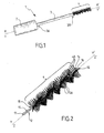
- the core 5 and the protuberances 4A thus go from the illustrated configuration to Figures 6 to 9 to the configuration illustrated at Figures 1 and 2 .
- the twisting means 12 comprises a U-shaped pin, the arms of the U being twisted and forming the two branches 12A, 12B, said arms of the U being connected by a cross-member 13 of curved shape extending in the extension of said branches 12A , 12B.
- the U-shaped pin is made of a metallic material, such as stainless steel, so that the twisting of the pin causes a permanent plastic deformation, according to a spiral profile around the axis. Z-Z ', branches 12A, 12B.
- Such an embodiment implementing, as twisting means 12, a pin with several branches is particularly interesting from an industrial point of view because it is based on a simple and proven general principle, since implemented for the manufacture of conventional twisted brushes.
- the degree of twisting of the twisting means 12 varies over the length of the latter, that is to say that the twisting means 12 has a number of turns which is not constant over its entire length.
- the twisting means 12 preferably comprises a first portion 14 which is in contact with the core 5, and preferably which extends over the entire length (for example substantially equal to 30 mm) of the latter (according to the invention). Y-Y 'axis) from the first end 16 of the twisting means 12, and a second portion 15 which is not in contact with the core 5, and which extends in the extension of the first portion 14 until at the second end 17 of the twisting means 12.
- the degree of twisting of the second portion 15 is advantageously greater than the degree
- the first portion 14 has five or six turns, while the second portion 15 has seven or eight turns.
- the method according to the invention is based in particular on the idea of twisting a three-dimensional core carrying the application growths, to make these growths abound in a generally helical profile.
- the steps (a), (b) and (c) are simultaneous and confounded, that is to say that the realization of the application excrescences 4A is concomitant and confused with the combination of said application growths 4A to the core 5.
- the realization of the application growths 4A simultaneously generates the association of said growths 4A to the core 5, and vice versa.
- This simultaneity can obviously be obtained when the application protuberances 4A come from material with the core 5, as described in the foregoing.
- the steps (a), (b) and (c) are advantageously combined into a single molding operation of a piece 6 in one piece forming both said core 5 and protrusion 4A.
- the method according to the invention comprises a step (e) of manufacturing and supplying a twisting means 12, as well as a step (f) of associating said twisting means 12 with said core 5 so that twisting the twisting means 12 generates a twist of the core 5, and thus a helical expansion of the protuberances 4A along the core 5.
- step (f) is subsequent to step (c), step (d) comprising twisting the twisting means 12 to twist the core 5 and thus generate said helical expansion.
- a twisting means 12 comprising two branches 12A, 12B delimiting between them an interstitial space 12C is manufactured or supplied.
- a twisting means 12 comprising a U-shaped pin is made or provided, the arms of the U forming said two elongate branches 12A, 12B. In this case, during step (f), the core 5 is inserted into said interstitial space 12C.
- the U-shaped pin which is preferably made by simple folding of a rectilinear and monobloc wire, is sometimes referred to in the technical field to which the invention relates by the term " stirrup".
- This pin advantageously comprises two branches, it being understood that the use of a greater number of branches is not excluded in the context of the invention.
- step (f) during which the twisting means 12 is attached to the core 5 is intended to provide a mechanical connection between the twisting means 12 and the core 5 designed so that a torsion deformation of the means of twisting 12 (twisting of the U-shaped pin) causes torsional deformation of the core 5 leading to a stable and permanent twisting of the latter along its longitudinal extension axis Y-Y '.
- the twisting of the first portion 14 is performed such that said first portion comprises five or six turns, while the twisting of the second portion 15 is performed so that said second portion 15 comprises seven or eight turns.
- the implementation of this particular twisting step which is subdivided into two sub-steps differentiated by their degree of twisting, makes it possible to adapt the structure of the twisting means 12 to the function assigned to it.
- the first portion 14 of the twisting means 12 must both have a mechanical strength (rigidity in particular) correct and impart a sufficient expansion of growths 4A, while the second portion 15 must have excellent mechanical behavior (especially the point in view of the rigidity) to achieve a stable, robust and durable assembly with the rod 3.
- the method according to the invention comprises an assembly step in which the unitary subassembly (illustrated in FIG. figure 2 ) formed by the twisting means 12 and the core 5, is fixed to the rod 3 by heating the second portion 15 of the twisting means 12 and screwing, while the second portion 15 is still hot, said second portion 15 in the distal end 3B of the shaft 3, which is preferably made of plastic.
- the second part 15 is thus screwed into force and hot in the distal end 3B of the rod 3, which ensures, after cooling of the rod 3, a stable and stable subjection of the application head 4 on and to the end of the stem 3.
- the general profile of the application means 4, formed by the plurality of excrescences 4A abounding helically, is modified by machining, that is to say by removal of material in the spiral layers formed by the protuberances 4A.
- the twisted core 5 carrying the protuberances 4A is finally secured by any appropriate means (crimping or gluing for example) to the rod 3, towards the distal end 3B of the latter, as shown in FIG. figure 1 .
- the twisted core 5 carrying the protuberances 4A thus forms an application head for the instrument 1 extending, from the distal end 3B, substantially in the extension of the rod 3 along the axis X-X ' .
- the manufacturing machine thus makes it possible to implement the method described in the foregoing, in order to obtain the instrument 1 according to the invention also described in the foregoing.
- the first twisting tool of the first portion 14 of the twisting means 12 comprises a pair of clamps, one of which is intended to grip the first end 16 of the twisting means 12, while the other is intended to grip the twisting means 12 at the separation interface 18 between the first portion 14 and the second portion 15 of the twisting means 12.
- the clamps are then rotated relative to each other along the axis Z-Z ', so as to obtain a twisting of the first part 14, said twisting being preferentially carried out so that said first part 14 comprises, after this operation five or six turns, as illustrated in FIG. figure 2 .
- the second twisting tool of the second portion 15 of the twisting means 12 comprises a pair of clamps, one of which is intended to grip the second end 17 of the twisting means 12 while the other is intended to to seize the twisting means 12 at the separation interface 18 between the first portion 14 and the second portion 15, said clamps being rotated relative to the axis ZZ 'to impart a twist of the second portion 15 , such that said second portion 15 advantageously has a greater number of turns than that of the first portion 14, and for example seven or eight turns.
- the invention finds its industrial application in the design, manufacture and use of instruments for applying products to superficial body growths, such as mascara brushes.
Landscapes
- Brushes (AREA)
- Prostheses (AREA)
- Cosmetics (AREA)
Claims (15)
- Instrument (1) zum Auftragen eines Produkts auf Hautanhangsgebilde, umfassend einerseits einen einteiligen Kern (5), der sich in Längsrichtung entlang einer mittleren Längsachse (Y-Y') erstreckt, und andererseits Fortsätze (4A) zum Auftragen des Produkts auf die Hautanhangsgebilde, wobei die Auftragfortsätze (4A) von dem Kern (5) getragen werden und spiralförmig an diesem entlang dicht besetzt ausgebildet sind, wobei die spiralförmige dicht besetzte Ausbildung der Fortsätze (4A) durch Verwinden des Kerns (5) erzielt wird, wobei das Instrument (1) ein Verwindungsmittel (12) umfasst, an dem der Kern (5) derart angebracht ist, dass die verwundene Beschaffenheit des Kerns (5) durch das Verwindungsmittel (12) verliehen wird, wobei das Instrument (1) dadurch gekennzeichnet ist, dass die Fortsätze (4A) auf dem Kern (5) vor der Verwindung desselben in mindestens drei unterschiedlichen radialen Richtungen (D1, D2, D3, D4) um die mittlere Längsachse (Y-Y') herum angeordnet sind.
- Instrument (1) nach Anspruch 1, dadurch gekennzeichnet, dass die Auftragfortsätze (4A) mit dem Kern (5) aus demselben Material einstückig geformt sind.
- Instrument (1) nach einem der Ansprüche 1 und 2, dadurch gekennzeichnet, dass der Kern (5) einerseits ein Kernstück (5A) und andererseits mindestens drei Flügel (7, 8, 9, 10, 11) umfasst, die sich radial von und entlang dem Kernstück (5A) erstrecken, wobei die Fortsätze (4A) von den Flügeln (7, 8, 9, 10, 11) getragen sind.
- Instrument (1) nach einem der Ansprüche 1 bis 3, dadurch gekennzeichnet, dass der Kern (5) und die Fortsätze (4A) ein einteiliges Stück (6) bilden, das durch einen Formvorgang erzielt wird.
- Instrument (1) nach einem der Ansprüche 1 bis 4, dadurch gekennzeichnet, dass das Verwindungsmittel (12) selbst verwunden ist.
- Instrument (1) nach Anspruch 5, dadurch gekennzeichnet, dass das Verwindungsmittel (12) mindestens zwei Schenkel (12A, 12B) umfasst, die zwischen sich einen Zwischenraum (12C) abgrenzen, in den der Kern (5) eingefügt wird.
- Instrument (1) nach Anspruch 6, dadurch gekennzeichnet, dass das Verwindungsmittel (12) eine U-förmige Nadel umfasst, wobei die Arme des U verwunden sind und die beiden Schenkel (12A, 12B) bilden.
- Instrument (1) nach einem der Ansprüche 5 bis 7, dadurch gekennzeichnet, dass der Verwindungsgrad des Verwindungsmittels (12) über die Länge desselben variiert.
- Instrument (1) nach Anspruch 8, dadurch gekennzeichnet, dass das Verwindungsmittel (12) einen ersten Teil (14), der in Kontakt mit dem Kern (5) steht, und einen zweiten Teil (15), der nicht in Kontakt mit dem Kern (5) steht, umfasst, wobei der Verwindungsgrad des zweiten Teils (15) größer als der Verwindungsgrad des ersten Teils (14) ist.
- Instrument (1) nach einem der Ansprüche 1 bis 9, dadurch gekennzeichnet, dass es einen Wimperntusche-Applikator bildet.
- Verfahren zum Herstellen eines Instruments (1), um ein Produkt auf Hautanhangsgebilde aufzutragen, umfassend einen Schritt (a) des Herstellens oder Bereitstellens eines einteiligen Kerns (5), der sich in Längsrichtung entlang einer mittleren Längsachse (Y-Y') erstreckt, einen Schritt (b) des Herstellens oder Bereitstellens von Fortsätzen (4A) zum Auftragen des Produkts auf die Hautanhangsgebilde, einen Schritt (c) des Verbindens der Auftragfortsätze (4A) mit dem Kern (5), so dass die Auftragfortsätze (4A) von dem Kern (5) getragen werden, einen Schritt (d) des Verwindens des Kerns (5), um eine spiralförmige dicht besetzte Ausbildung der Fortsätze (4A) entlang dem Kern (5) zu erzeugen, einen Schritt (e) des Herstellens oder Bereitstellens eines Verwindungsmittels (12), sowie einen Schritt (f) des Verbindens des Verwindungsmittels (12) mit dem Kern (5), so dass eine Verwindung des Verwindungsmittels (12) eine Verwindung des Kerns (5) erzeugt, wobei das Verfahren dadurch gekennzeichnet ist, dass in Schritt (c) die Auftragfortsätze (4A) mit dem Kern (5) verbunden werden, so dass die Auftragfortsätze (4A) darauf in mindestens drei unterschiedlichen radialen Richtungen (D1, D2, D3, D4) um die mittlere Längsachse (Y-Y') herum angeordnet sind.
- Verfahren nach Anspruch 11, dadurch gekennzeichnet, dass der Schritt (f) nach dem Schritt (c) folgt, wobei der Schritt (d) eine Verwindung des Verwindungsmittels (12) umfasst, um den Kern (5) zu verwinden und somit die spiralförmige dicht besetzte Ausbildung zu erzeugen.
- Verfahren nach Anspruch 12, dadurch gekennzeichnet, dass die in Schritt (d) umgesetzte Verwindung derart erfolgt, dass der Verwindungsgrad des Verwindungsmittels (12) über die Länge desselben variiert.
- Verfahren nach einem der Ansprüche 11 bis 13, dadurch gekennzeichnet, dass es ein Verfahren zum Herstellen eines Wimperntusche-Applikators ist.
- Maschine zum Herstellen eines Instruments (1) zum Auftragen eines Produkts auf Hautanhangsgebilde, umfassend:- eine Station zum Herstellen oder Bereitstellen eines einteiligen Kerns (5), der sich in Längsrichtung entlang einer mittleren Längsachse (Y-Y') erstreckt,- eine Station zum Herstellen oder Bereitstellen von Fortsätzen (4A) zum Auftragen des Produkts auf die Hautanhangsgebilde,- eine Station zum Verbinden der Auftragfartsätze (4A) mit dem Kern (5), so dass die Auftragfortsätze (4A) von dem Kern (5) getragen werden und darauf in mindestens drei unterschiedlichen radialen Richtungen (D1, D2, D3, D4) um die mittlere Längsachse (Y-Y') herum angeordnet sind,- eine Station zum Verwinden des Kerns (5), um eine spiralförmige dicht besetzte Ausbildung der Fortsätze (4A) entlang dem Kern (5) zu erzeugen,wobei die Verwindungsstation Folgendes umfasst:- eine Nebenstation zum Herstellen oder Bereitstellen eines Verwindungsmittels (12),- eine Nebenstation zum Verbinden des Verwindungsmittels (12) mit dem Kern (5), so dass eine Verwindung des Verwindungsmittels (12) eine Verwindung des Kerns (5) erzeugt,- und eine Nebenstation zum Verwinden des Verwindungsmittels (12), um den Kern (5) zu verwinden und somit die spiralförmige dicht besetzte Ausbildung zu erzeugen.
Applications Claiming Priority (1)
| Application Number | Priority Date | Filing Date | Title |
|---|---|---|---|
| FR0805505A FR2936691B1 (fr) | 2008-10-06 | 2008-10-06 | Instrument pour appliquer un produit sur des phaneres et procede de fabrication afferent |
Publications (2)
| Publication Number | Publication Date |
|---|---|
| EP2172127A1 EP2172127A1 (de) | 2010-04-07 |
| EP2172127B1 true EP2172127B1 (de) | 2015-05-27 |
Family
ID=40612768
Family Applications (1)
| Application Number | Title | Priority Date | Filing Date |
|---|---|---|---|
| EP09305942.6A Active EP2172127B1 (de) | 2008-10-06 | 2009-10-05 | Instrument zum Aufbringen eines Produkts auf Hautanhangsorgane und entsprechendes Herstellungsverfahren |
Country Status (7)
| Country | Link |
|---|---|
| US (1) | US8636013B2 (de) |
| EP (1) | EP2172127B1 (de) |
| JP (1) | JP5657231B2 (de) |
| CN (1) | CN101721040B (de) |
| BR (1) | BRPI0903992B1 (de) |
| ES (1) | ES2545973T3 (de) |
| FR (1) | FR2936691B1 (de) |
Families Citing this family (18)
| Publication number | Priority date | Publication date | Assignee | Title |
|---|---|---|---|---|
| FR2913572B1 (fr) * | 2007-03-16 | 2009-06-05 | Chanel Parfums Beaute Soc Par | Applicateur pour appliquer un produit sur les cils |
| US20090276973A1 (en) * | 2008-05-06 | 2009-11-12 | Herve Bouix | Cosmetic Applicator Assembly |
| US8136536B2 (en) * | 2008-09-24 | 2012-03-20 | Elc Management Llc | Shape memory polymer mascara brush |
| FR2958130B1 (fr) * | 2010-03-30 | 2012-06-08 | Oreal | Applicateur pour appliquer un produit sur les cils et/ou sourcils. |
| CN103202596A (zh) * | 2012-01-13 | 2013-07-17 | 王学德 | 一种锅碗刷植鬃机 |
| DE202013006746U1 (de) * | 2013-07-29 | 2014-10-31 | Geka Gmbh | Drahtkernbürste mit mehreren Schlaufen aus einem einzigen Filament |
| FR3014656B1 (fr) | 2013-12-17 | 2017-04-28 | Oreal | Applicateur d'un produit cosmetique, de maquillage ou de soin, sur les cils et/ou les sourcils |
| JP2016521193A (ja) * | 2014-05-09 | 2016-07-21 | エーエー アールアンドディー エルエルシー | 化粧用ねじりブラシ |
| FR3028396B1 (fr) | 2014-11-14 | 2018-01-26 | L'oreal | Applicateur pour appliquer un produit sur les cils |
| WO2016178702A1 (en) * | 2015-05-01 | 2016-11-10 | Aa R & D Llc | Assembly technology for any shape disk brush |
| FR3042391B1 (fr) | 2015-10-19 | 2020-03-20 | L'oreal | Applicateur de produit cosmetique |
| FR3054779B1 (fr) * | 2016-08-04 | 2019-06-28 | L'oreal | Applicateur pour les cils ou les sourcils. |
| US10681974B2 (en) | 2017-04-04 | 2020-06-16 | Ranir, Llc | Interdental toothbrush |
| FR3066367B1 (fr) | 2017-05-16 | 2019-07-05 | L'oreal | Applicateur pour appliquer un produit sur les cils |
| FR3087326B1 (fr) * | 2018-10-17 | 2020-11-06 | Oreal | Organe d'application d'un produit a deux types d'elements d'application intercales, dispositif de conditionnement et d'application comprenant un tel organe d'application et procede de fabrication dudit organe d'application |
| FR3089766B1 (fr) | 2018-12-18 | 2021-09-24 | Oreal | Organe d’application d’un produit et procédé de fabrication dudit organe d’application |
| FR3089773B1 (fr) | 2018-12-18 | 2021-01-22 | Oreal | Organe d’application d’un produit et procédé de fabrication dudit organe d’application |
| FR3091983B1 (fr) | 2019-01-28 | 2021-04-30 | Texen Services | Application d’un produit sur une partie superficielle du corps humain |
Family Cites Families (20)
| Publication number | Priority date | Publication date | Assignee | Title |
|---|---|---|---|---|
| US8021A (en) * | 1851-04-01 | Brick-press | ||
| US4733425A (en) * | 1986-06-16 | 1988-03-29 | Sanderson-Macleod, Inc. | Mascara brush |
| FR2607372B1 (fr) * | 1986-11-28 | 1991-04-05 | Oreal | Brosse pour l'application de produits cosmetiques, en particulier de mascara |
| FR2627068B1 (fr) * | 1988-02-12 | 1990-12-07 | Oreal | Brosse pour l'application d'un produit de maquillage, notamment de mascara, et reservoir de produit equipe d'une telle brosse |
| US5551456A (en) * | 1994-11-03 | 1996-09-03 | Sanderson-Macleod, Inc. | Mascara brush construction |
| FR2748913B1 (fr) * | 1996-05-24 | 1998-08-07 | Oreal | Brosse a crans et dispositif de maquillage comprenant cette brosse |
| FR2762494B1 (fr) * | 1997-04-28 | 1999-06-25 | Oreal | Applicateur et ensemble de conditionnement et d'application utilisant un tel applicateur |
| US6241411B1 (en) * | 1999-04-19 | 2001-06-05 | Revlon Consumer Products Corporation | Mascara brush, container, and method |
| FR2796530B1 (fr) * | 1999-07-21 | 2001-09-21 | Oreal | Dispositif pour le peignage des cils ou des sourcils et dispositif de conditionnement et d'application ainsi equipe |
| US6427700B1 (en) * | 2000-05-08 | 2002-08-06 | Revlon Consumer Products Corporation | Mascara brush, container, and method |
| BR0300549A (pt) * | 2002-03-05 | 2003-11-11 | Oreal | Dispositivos para pentear os cìlios e/ou as sobrancelhas e/ou aplicar um produto sobre os mesmos, para aplicar um produto sobre os cìlios e/ou as sobrancelhas e para acondicionar e aplicar um produto sobre os cìlios e/ou as sobrancelhas, processos de maquiagem dos cìlios e/ou das sobrancelhas, de fabricação de uma escova e de aplicação de um produto sobre os cìlios e/ou as sobrancelhas e escova para a aplicação de um produto sobre os cìlios e/ou as sobrancelhas |
| DE10232589A1 (de) * | 2002-07-18 | 2004-01-29 | Geka Brush Gmbh | Mascara-Bürstchen |
| AU2003299964A1 (en) * | 2002-12-31 | 2004-07-29 | Avon Products, Inc. | Applicator brush for a cosmetic product |
| FR2850549B1 (fr) * | 2003-02-04 | 2006-07-14 | Oreal | Brosse pour l'application d'un produit sur les cils ou les sourcils |
| JP2006204904A (ja) * | 2004-12-28 | 2006-08-10 | Kao Corp | マスカラ塗布具 |
| FR2900319B1 (fr) * | 2006-04-28 | 2008-07-11 | Saint Laurent Parfums | Instrument d'application d'un produit sur les phaneres et son procede de fabrication |
| FR2900318B1 (fr) * | 2006-04-28 | 2008-07-11 | Saint Laurent Parfums | Instrument d'application de construction simplifiee et procede de fabrication afferent |
| FR2902984B1 (fr) * | 2006-06-28 | 2009-03-20 | Oreal | Dispositif pour l'application d'un produit sur les cils ou les sourcils. |
| FR2912620B1 (fr) * | 2007-02-21 | 2010-08-13 | Chanel Parfums Beaute | Procede de fabrication d'un applicateur de produit cosmetique, applicateur, emballage comprenant cet applicateur et lot d'applicateurs. |
| US8136536B2 (en) * | 2008-09-24 | 2012-03-20 | Elc Management Llc | Shape memory polymer mascara brush |
-
2008
- 2008-10-06 FR FR0805505A patent/FR2936691B1/fr active Active
-
2009
- 2009-10-05 ES ES09305942.6T patent/ES2545973T3/es active Active
- 2009-10-05 EP EP09305942.6A patent/EP2172127B1/de active Active
- 2009-10-06 BR BRPI0903992-9A patent/BRPI0903992B1/pt active IP Right Grant
- 2009-10-06 JP JP2009232464A patent/JP5657231B2/ja active Active
- 2009-10-06 US US12/574,515 patent/US8636013B2/en active Active
- 2009-10-09 CN CN2009102116961A patent/CN101721040B/zh active Active
Also Published As
| Publication number | Publication date |
|---|---|
| JP5657231B2 (ja) | 2015-01-21 |
| BRPI0903992B1 (pt) | 2019-06-18 |
| BRPI0903992A2 (pt) | 2010-07-20 |
| US8636013B2 (en) | 2014-01-28 |
| US20100089415A1 (en) | 2010-04-15 |
| CN101721040B (zh) | 2012-11-07 |
| CN101721040A (zh) | 2010-06-09 |
| FR2936691B1 (fr) | 2012-12-07 |
| FR2936691A1 (fr) | 2010-04-09 |
| ES2545973T3 (es) | 2015-09-17 |
| JP2010088889A (ja) | 2010-04-22 |
| EP2172127A1 (de) | 2010-04-07 |
Similar Documents
| Publication | Publication Date | Title |
|---|---|---|
| EP2172127A1 (de) | Instrument zum Aufbringen eines Produkts auf Hautanhangsorgane und entsprechendes Herstellungsverfahren | |
| EP2012614B1 (de) | Anwendungsinstrument mit vereinfachter konstruktion und zugeordnetes herstellungsverfahren | |
| EP1236421B2 (de) | Vorrichtung, insbesondere Bürste, zum Auftragen eines Produktes auf keratinische Fasern | |
| EP2012615B1 (de) | Instrument zum auftragen eines produkts auf oberflächenepithelanhanggebilde und herstellungsverfahren dafür | |
| EP2134208B1 (de) | Verfahren zum auftragen eines produkts auf augenwimpern | |
| EP0978241B1 (de) | Vorrichtung zum Auftragen von Schminkprodukten mit einer Bürste, Verfahren zu dessen Herstellung und Auftragseinheit mit einer solchen Vorrichtung | |
| EP2229840B1 (de) | Applikator zum Auftragen eines Kosmetik-, Schmink- oder Pflegeproduktes, und Verfahren zu seiner Herstellung | |
| EP1977662B1 (de) | Applikator zum Auftragen einer Zusammensetzung auf die Wimpern | |
| EP1977661B1 (de) | Applikator zum Auftragen einer Zusammensetzung auf die Wimpern | |
| FR2812176A1 (fr) | Applicateur pour l'application d'un produit sur des fibres keratiniques, ensemble d'application equipe d'un tel applicateur, et utilisation de cet ensemble | |
| EP2555652B1 (de) | Doppelapplikator zum auftragen eines produkts auf die wimpern | |
| EP1236419A1 (de) | Bürste zum Auftragen eines Produktes auf keratinische Faser | |
| EP1236420A1 (de) | Bürste zum Auftragen eines Produktes auf keratinische Fasern | |
| EP1938709A1 (de) | Mascarabürste | |
| FR2991560A1 (fr) | Applicateur pour l'application d'un produit cosmetique ou de soin sur les cils ou les sourcils. | |
| FR3013569A1 (fr) | Procede de fabrication d'une brosse | |
| WO2021069850A1 (fr) | Applicateur pour mascara | |
| EP1369056A1 (de) | Applikator mit einer Stange, die durch ein Gelenk mit einem Griff verbunden ist und mit einem schrägen Applikatorelement | |
| FR2937514A1 (fr) | Dispositif applicateur d'un produit cosmetique fluide ou pateux, typiquement du mascara | |
| EP1454561B1 (de) | Auftragevorrichtung und Aufbewahrungs- und Ausgabevorrichtung mit einer solchen Auftragevorrichtung | |
| FR3048594B1 (fr) | Applicateur de produit cosmetique | |
| EP3136905A1 (de) | Applikator für kosmetisches produkt, im besonderen für mascara, und verfahren zur herstellung solch eines applikators |
Legal Events
| Date | Code | Title | Description |
|---|---|---|---|
| PUAI | Public reference made under article 153(3) epc to a published international application that has entered the european phase |
Free format text: ORIGINAL CODE: 0009012 |
|
| AK | Designated contracting states |
Kind code of ref document: A1 Designated state(s): AT BE BG CH CY CZ DE DK EE ES FI FR GB GR HR HU IE IS IT LI LT LU LV MC MK MT NL NO PL PT RO SE SI SK SM TR |
|
| 17P | Request for examination filed |
Effective date: 20101001 |
|
| 17Q | First examination report despatched |
Effective date: 20101111 |
|
| GRAP | Despatch of communication of intention to grant a patent |
Free format text: ORIGINAL CODE: EPIDOSNIGR1 |
|
| INTG | Intention to grant announced |
Effective date: 20141210 |
|
| GRAS | Grant fee paid |
Free format text: ORIGINAL CODE: EPIDOSNIGR3 |
|
| GRAA | (expected) grant |
Free format text: ORIGINAL CODE: 0009210 |
|
| AK | Designated contracting states |
Kind code of ref document: B1 Designated state(s): AT BE BG CH CY CZ DE DK EE ES FI FR GB GR HR HU IE IS IT LI LT LU LV MC MK MT NL NO PL PT RO SE SI SK SM TR |
|
| REG | Reference to a national code |
Ref country code: GB Ref legal event code: FG4D Free format text: NOT ENGLISH |
|
| REG | Reference to a national code |
Ref country code: CH Ref legal event code: EP |
|
| REG | Reference to a national code |
Ref country code: AT Ref legal event code: REF Ref document number: 728357 Country of ref document: AT Kind code of ref document: T Effective date: 20150615 |
|
| REG | Reference to a national code |
Ref country code: IE Ref legal event code: FG4D Free format text: LANGUAGE OF EP DOCUMENT: FRENCH |
|
| REG | Reference to a national code |
Ref country code: DE Ref legal event code: R096 Ref document number: 602009031412 Country of ref document: DE |
|
| REG | Reference to a national code |
Ref country code: ES Ref legal event code: FG2A Ref document number: 2545973 Country of ref document: ES Kind code of ref document: T3 Effective date: 20150917 |
|
| REG | Reference to a national code |
Ref country code: AT Ref legal event code: MK05 Ref document number: 728357 Country of ref document: AT Kind code of ref document: T Effective date: 20150527 |
|
| REG | Reference to a national code |
Ref country code: LT Ref legal event code: MG4D |
|
| PG25 | Lapsed in a contracting state [announced via postgrant information from national office to epo] |
Ref country code: FI Free format text: LAPSE BECAUSE OF FAILURE TO SUBMIT A TRANSLATION OF THE DESCRIPTION OR TO PAY THE FEE WITHIN THE PRESCRIBED TIME-LIMIT Effective date: 20150527 Ref country code: PT Free format text: LAPSE BECAUSE OF FAILURE TO SUBMIT A TRANSLATION OF THE DESCRIPTION OR TO PAY THE FEE WITHIN THE PRESCRIBED TIME-LIMIT Effective date: 20150928 Ref country code: HR Free format text: LAPSE BECAUSE OF FAILURE TO SUBMIT A TRANSLATION OF THE DESCRIPTION OR TO PAY THE FEE WITHIN THE PRESCRIBED TIME-LIMIT Effective date: 20150527 Ref country code: NO Free format text: LAPSE BECAUSE OF FAILURE TO SUBMIT A TRANSLATION OF THE DESCRIPTION OR TO PAY THE FEE WITHIN THE PRESCRIBED TIME-LIMIT Effective date: 20150827 Ref country code: LT Free format text: LAPSE BECAUSE OF FAILURE TO SUBMIT A TRANSLATION OF THE DESCRIPTION OR TO PAY THE FEE WITHIN THE PRESCRIBED TIME-LIMIT Effective date: 20150527 |
|
| REG | Reference to a national code |
Ref country code: NL Ref legal event code: MP Effective date: 20150527 |
|
| PG25 | Lapsed in a contracting state [announced via postgrant information from national office to epo] |
Ref country code: GR Free format text: LAPSE BECAUSE OF FAILURE TO SUBMIT A TRANSLATION OF THE DESCRIPTION OR TO PAY THE FEE WITHIN THE PRESCRIBED TIME-LIMIT Effective date: 20150828 Ref country code: LV Free format text: LAPSE BECAUSE OF FAILURE TO SUBMIT A TRANSLATION OF THE DESCRIPTION OR TO PAY THE FEE WITHIN THE PRESCRIBED TIME-LIMIT Effective date: 20150527 Ref country code: BG Free format text: LAPSE BECAUSE OF FAILURE TO SUBMIT A TRANSLATION OF THE DESCRIPTION OR TO PAY THE FEE WITHIN THE PRESCRIBED TIME-LIMIT Effective date: 20150827 Ref country code: AT Free format text: LAPSE BECAUSE OF FAILURE TO SUBMIT A TRANSLATION OF THE DESCRIPTION OR TO PAY THE FEE WITHIN THE PRESCRIBED TIME-LIMIT Effective date: 20150527 Ref country code: IS Free format text: LAPSE BECAUSE OF FAILURE TO SUBMIT A TRANSLATION OF THE DESCRIPTION OR TO PAY THE FEE WITHIN THE PRESCRIBED TIME-LIMIT Effective date: 20150927 |
|
| PG25 | Lapsed in a contracting state [announced via postgrant information from national office to epo] |
Ref country code: EE Free format text: LAPSE BECAUSE OF FAILURE TO SUBMIT A TRANSLATION OF THE DESCRIPTION OR TO PAY THE FEE WITHIN THE PRESCRIBED TIME-LIMIT Effective date: 20150527 Ref country code: DK Free format text: LAPSE BECAUSE OF FAILURE TO SUBMIT A TRANSLATION OF THE DESCRIPTION OR TO PAY THE FEE WITHIN THE PRESCRIBED TIME-LIMIT Effective date: 20150527 |
|
| PG25 | Lapsed in a contracting state [announced via postgrant information from national office to epo] |
Ref country code: PL Free format text: LAPSE BECAUSE OF FAILURE TO SUBMIT A TRANSLATION OF THE DESCRIPTION OR TO PAY THE FEE WITHIN THE PRESCRIBED TIME-LIMIT Effective date: 20150527 Ref country code: SK Free format text: LAPSE BECAUSE OF FAILURE TO SUBMIT A TRANSLATION OF THE DESCRIPTION OR TO PAY THE FEE WITHIN THE PRESCRIBED TIME-LIMIT Effective date: 20150527 Ref country code: RO Free format text: LAPSE BECAUSE OF NON-PAYMENT OF DUE FEES Effective date: 20150527 Ref country code: CZ Free format text: LAPSE BECAUSE OF FAILURE TO SUBMIT A TRANSLATION OF THE DESCRIPTION OR TO PAY THE FEE WITHIN THE PRESCRIBED TIME-LIMIT Effective date: 20150527 |
|
| REG | Reference to a national code |
Ref country code: DE Ref legal event code: R097 Ref document number: 602009031412 Country of ref document: DE |
|
| PLBE | No opposition filed within time limit |
Free format text: ORIGINAL CODE: 0009261 |
|
| STAA | Information on the status of an ep patent application or granted ep patent |
Free format text: STATUS: NO OPPOSITION FILED WITHIN TIME LIMIT |
|
| 26N | No opposition filed |
Effective date: 20160301 |
|
| PG25 | Lapsed in a contracting state [announced via postgrant information from national office to epo] |
Ref country code: SI Free format text: LAPSE BECAUSE OF FAILURE TO SUBMIT A TRANSLATION OF THE DESCRIPTION OR TO PAY THE FEE WITHIN THE PRESCRIBED TIME-LIMIT Effective date: 20150527 Ref country code: LU Free format text: LAPSE BECAUSE OF FAILURE TO SUBMIT A TRANSLATION OF THE DESCRIPTION OR TO PAY THE FEE WITHIN THE PRESCRIBED TIME-LIMIT Effective date: 20151005 |
|
| REG | Reference to a national code |
Ref country code: CH Ref legal event code: PL |
|
| PG25 | Lapsed in a contracting state [announced via postgrant information from national office to epo] |
Ref country code: MC Free format text: LAPSE BECAUSE OF FAILURE TO SUBMIT A TRANSLATION OF THE DESCRIPTION OR TO PAY THE FEE WITHIN THE PRESCRIBED TIME-LIMIT Effective date: 20150527 |
|
| REG | Reference to a national code |
Ref country code: IE Ref legal event code: MM4A |
|
| PG25 | Lapsed in a contracting state [announced via postgrant information from national office to epo] |
Ref country code: CH Free format text: LAPSE BECAUSE OF NON-PAYMENT OF DUE FEES Effective date: 20151031 Ref country code: LI Free format text: LAPSE BECAUSE OF NON-PAYMENT OF DUE FEES Effective date: 20151031 |
|
| REG | Reference to a national code |
Ref country code: FR Ref legal event code: PLFP Year of fee payment: 8 |
|
| PG25 | Lapsed in a contracting state [announced via postgrant information from national office to epo] |
Ref country code: IE Free format text: LAPSE BECAUSE OF NON-PAYMENT OF DUE FEES Effective date: 20151005 |
|
| PG25 | Lapsed in a contracting state [announced via postgrant information from national office to epo] |
Ref country code: SM Free format text: LAPSE BECAUSE OF FAILURE TO SUBMIT A TRANSLATION OF THE DESCRIPTION OR TO PAY THE FEE WITHIN THE PRESCRIBED TIME-LIMIT Effective date: 20150527 Ref country code: HU Free format text: LAPSE BECAUSE OF FAILURE TO SUBMIT A TRANSLATION OF THE DESCRIPTION OR TO PAY THE FEE WITHIN THE PRESCRIBED TIME-LIMIT; INVALID AB INITIO Effective date: 20091005 |
|
| PG25 | Lapsed in a contracting state [announced via postgrant information from national office to epo] |
Ref country code: CY Free format text: LAPSE BECAUSE OF FAILURE TO SUBMIT A TRANSLATION OF THE DESCRIPTION OR TO PAY THE FEE WITHIN THE PRESCRIBED TIME-LIMIT Effective date: 20150527 Ref country code: SE Free format text: LAPSE BECAUSE OF FAILURE TO SUBMIT A TRANSLATION OF THE DESCRIPTION OR TO PAY THE FEE WITHIN THE PRESCRIBED TIME-LIMIT Effective date: 20150527 Ref country code: NL Free format text: LAPSE BECAUSE OF FAILURE TO SUBMIT A TRANSLATION OF THE DESCRIPTION OR TO PAY THE FEE WITHIN THE PRESCRIBED TIME-LIMIT Effective date: 20150527 |
|
| PG25 | Lapsed in a contracting state [announced via postgrant information from national office to epo] |
Ref country code: BE Free format text: LAPSE BECAUSE OF NON-PAYMENT OF DUE FEES Effective date: 20151031 |
|
| PG25 | Lapsed in a contracting state [announced via postgrant information from national office to epo] |
Ref country code: MT Free format text: LAPSE BECAUSE OF FAILURE TO SUBMIT A TRANSLATION OF THE DESCRIPTION OR TO PAY THE FEE WITHIN THE PRESCRIBED TIME-LIMIT Effective date: 20150527 Ref country code: TR Free format text: LAPSE BECAUSE OF FAILURE TO SUBMIT A TRANSLATION OF THE DESCRIPTION OR TO PAY THE FEE WITHIN THE PRESCRIBED TIME-LIMIT Effective date: 20150527 |
|
| REG | Reference to a national code |
Ref country code: FR Ref legal event code: PLFP Year of fee payment: 9 |
|
| PG25 | Lapsed in a contracting state [announced via postgrant information from national office to epo] |
Ref country code: MK Free format text: LAPSE BECAUSE OF FAILURE TO SUBMIT A TRANSLATION OF THE DESCRIPTION OR TO PAY THE FEE WITHIN THE PRESCRIBED TIME-LIMIT Effective date: 20150527 |
|
| REG | Reference to a national code |
Ref country code: FR Ref legal event code: PLFP Year of fee payment: 10 |
|
| PGFP | Annual fee paid to national office [announced via postgrant information from national office to epo] |
Ref country code: IT Payment date: 20250922 Year of fee payment: 17 |
|
| PGFP | Annual fee paid to national office [announced via postgrant information from national office to epo] |
Ref country code: GB Payment date: 20250904 Year of fee payment: 17 |
|
| PGFP | Annual fee paid to national office [announced via postgrant information from national office to epo] |
Ref country code: FR Payment date: 20250908 Year of fee payment: 17 |
|
| PGFP | Annual fee paid to national office [announced via postgrant information from national office to epo] |
Ref country code: DE Payment date: 20250902 Year of fee payment: 17 |
|
| PGFP | Annual fee paid to national office [announced via postgrant information from national office to epo] |
Ref country code: ES Payment date: 20251106 Year of fee payment: 17 |