EP2172140A2 - Vorrichtung zur Aufhängung von Vorhängen - Google Patents
Vorrichtung zur Aufhängung von Vorhängen Download PDFInfo
- Publication number
- EP2172140A2 EP2172140A2 EP20090171428 EP09171428A EP2172140A2 EP 2172140 A2 EP2172140 A2 EP 2172140A2 EP 20090171428 EP20090171428 EP 20090171428 EP 09171428 A EP09171428 A EP 09171428A EP 2172140 A2 EP2172140 A2 EP 2172140A2
- Authority
- EP
- European Patent Office
- Prior art keywords
- faces
- ring
- curtain
- flange
- clamp
- Prior art date
- Legal status (The legal status is an assumption and is not a legal conclusion. Google has not performed a legal analysis and makes no representation as to the accuracy of the status listed.)
- Withdrawn
Links
- 230000000295 complement effect Effects 0.000 claims abstract description 14
- 239000000463 material Substances 0.000 claims abstract description 5
- 229920002457 flexible plastic Polymers 0.000 claims abstract description 3
- 238000000465 moulding Methods 0.000 claims abstract description 3
- 230000002093 peripheral effect Effects 0.000 claims description 10
- 239000011324 bead Substances 0.000 claims description 4
- 125000006850 spacer group Chemical group 0.000 claims description 3
- 230000005489 elastic deformation Effects 0.000 claims description 2
- 239000000725 suspension Substances 0.000 description 6
- 239000004744 fabric Substances 0.000 description 2
- 206010048232 Yawning Diseases 0.000 description 1
- 238000002955 isolation Methods 0.000 description 1
Images


Classifications
-
- A—HUMAN NECESSITIES
- A47—FURNITURE; DOMESTIC ARTICLES OR APPLIANCES; COFFEE MILLS; SPICE MILLS; SUCTION CLEANERS IN GENERAL
- A47H—FURNISHINGS FOR WINDOWS OR DOORS
- A47H13/00—Fastening curtains on curtain rods or rails
- A47H13/02—Fastening curtains on curtain rods or rails by rings, e.g. with additional runners
-
- A—HUMAN NECESSITIES
- A44—HABERDASHERY; JEWELLERY
- A44B—BUTTONS, PINS, BUCKLES, SLIDE FASTENERS, OR THE LIKE
- A44B13/00—Hook or eye fasteners
- A44B13/0058—Eyelets or grommets
- A44B13/0076—Eyelets or grommets characterised by their way of fastening to the support
- A44B13/0088—Eyelets or grommets characterised by their way of fastening to the support by separable snap connection
Definitions
- the present invention relates to a device for suspending a curtain.
- devices are also widely distributed comprising a lower part forming a clamp intended to grip the edge of the curtain and an upper part comprising generally a hook, intended to cooperate with the rod.
- the present invention aims to overcome all of these disadvantages by providing a device that is both effective and very simple, and therefore inexpensive.
- the invention relates to a device for suspending a curtain, of the type comprising a lower part forming a clamp intended to grip a selvedge of the curtain, and an upper part constituted by a ring intended to cooperate with a rod, characterized in that that the clamp and the ring are constituted by two separate complementary piece faces, superimposable in relation to their joint plane and their axes of symmetry, said connection being effected via also complementary internal connecting means, for obtaining a clamp-ring assembly, in one piece.
- the present invention also relates to the features which will emerge during the following description, which should be considered in isolation or in all their possible technical combinations.
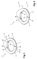
- the device 1 generally designated in the figures is intended for the suspension of a curtain 2.
- This device is of the type comprising a lower part forming a clamp 3, intended to grip a selvedge of the curtain 2, and an upper part constituted by a ring 4, which is intended to cooperate with a rod 5.
- the clamp 3 and the ring 4 are constituted by two complementary monobloc complementary faces, superimposable 6.7 with respect to their joint plane 8 and their axis of symmetry, said assembly being effected by means of internal connection means also complementary, for obtaining a set 1 clamp 3 - ring 4, in one piece.
- each of the complementary faces 6,7 the component is constituted generally by a circular ring 8,9 defining the ring 4, whose central portion defines a circular opening 10,11 intended for the bead passage 5, and whose periphery of its circular portion is extended by an appendix 12,13 defining the area of the clamp 3, forming generally an ellipse.
- the circular central portion 11 of the ring 9 of one of the faces 7 forms a peripheral flange 14 having an external groove 15 intended to cooperate in closure by elastic snapping with a corresponding bead 16, realized on a peripheral collar 17 of the central portion 10 of the other face 6.
- the peripheral collar 17 of the circular central portion 10 of the crown 8 of one of the faces 6 is doubled, at least punctually, by internal collar portions 18 concentric with said peripheral collar 17 , between which flanges 17,18 of the face 6 is likely to the flange 14 of the other face 7, on which stiffening bosses are made, fit together.
- peripheral flanges 17 and 14 of the faces 6 and 7 comprise means of indexing and guiding one with respect to the other, constituted by two notches 19 distributed in a balanced manner on the periphery of the flange 17 of one of the faces 6 and intended to receive corresponding fingers 20 made on the outer periphery of the flange 14 of the other face 7.
- complementary closure means of the faces 6, 7 composing the device 1 are added to their resilient snap-fastening means 15, 16 and consist of cylindrical male studs 21, made on the one of the faces 7, in coincidence with hollow cylindrical spacers 22 with which they cooperate in the assembly.
- the height of the hollow cylindrical spacers 21 is greater than the height of the pins 22 and has a free end flared to allow the introduction and easy guiding of the pads 22 during assembly, and likely to bloom and crashing at the end of assembly to absorb the difference in height mentioned above.
- appendices 12,13 defining the area of the clamp 4 have, within their faces 6,7, fastening means of the edge of the curtain 2, consisting on the one hand blind housing 23 and secondly, corresponding pins 24, made coincidentally some of the other, so that after interposition of the curtain 2 between the faces 6,7, during assembly, the pins 24 perforate the curtain 2 and enter the corresponding housing 23.
- the device 1 thus described could perfectly be used as such for mounting and hanging curtains on a rod, but after disassembly thereof.
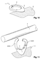
- the faces 6,7 the component are made of flexible material, and in that the ring-shaped zone 8,9 defining the ring 4 is cut off 33, 34 in its upper part, in or near its axis of symmetry, so as to define two branches 4A, 4B-4C, 4D of the ring 4 being spaced apart from each other, by elastic deformation, after mounting on the curtain 2, to allow the passage of the rod 5, then to close on it, without disassembly.
- the cutouts 33, 34 of the faces 6, 7 in the upper zone of the ring 4 are offset with respect to each other, so as to present, after assembly, shoulders 27,28 allowing an abutment of one of the faces 6 forming the ring 4 on the other 7.
- the shoulders 27,28 for abutting the faces 6,7 of the ring 4 comprise locking means 29,30 by snap elastically.
- These means are constituted by a finger 29 of the face 6 which can snap, when mounted, on a notch 30 of the face 7.
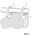
- two pairs of tabs 31 are formed on either side of their axis of symmetry. 32 coming into lateral abutment of one another during assembly, so as to absorb the forces at the moment of twisting the branches of the ring 4 during assembly, the tab 32 being raised relative to the collar to allow the passage of the tab 31 under said tab 32, so that said forces do not reverberate at the clamp 3.
- This feature is intended to prevent the clamp area 3 to yawn during twisting of the ring, which could cause the curtain to separate from said clamp.
- the faces 6,7 the component are obtained by molding a flexible plastic material.
Landscapes
- Curtains And Furnishings For Windows Or Doors (AREA)
Applications Claiming Priority (1)
| Application Number | Priority Date | Filing Date | Title |
|---|---|---|---|
| FR0856653A FR2936402A1 (fr) | 2008-10-01 | 2008-10-01 | Dispositif de suspension de rideau |
Publications (1)
| Publication Number | Publication Date |
|---|---|
| EP2172140A2 true EP2172140A2 (de) | 2010-04-07 |
Family
ID=40551442
Family Applications (1)
| Application Number | Title | Priority Date | Filing Date |
|---|---|---|---|
| EP20090171428 Withdrawn EP2172140A2 (de) | 2008-10-01 | 2009-09-26 | Vorrichtung zur Aufhängung von Vorhängen |
Country Status (2)
| Country | Link |
|---|---|
| EP (1) | EP2172140A2 (de) |
| FR (1) | FR2936402A1 (de) |
Cited By (2)
| Publication number | Priority date | Publication date | Assignee | Title |
|---|---|---|---|---|
| AT517375A1 (de) * | 2015-06-25 | 2017-01-15 | Georg Fuchs | Anordnung und Verbindungsvorrichtung |
| WO2022049281A1 (en) * | 2020-09-04 | 2022-03-10 | Tecnicarton S.L. | Plastic eyelet |
Family Cites Families (4)
| Publication number | Priority date | Publication date | Assignee | Title |
|---|---|---|---|---|
| US4843675A (en) * | 1988-09-23 | 1989-07-04 | Panayiotis Diamantis | Two piece removable-curtain grommet |
| US6189597B1 (en) * | 1999-10-13 | 2001-02-20 | Wen Ping Cheng | Hanger ring assembly for curtain |
| DE10244053A1 (de) * | 2002-09-21 | 2004-03-25 | Nodeko Gmbh Handels- Und Vertriebsgesellschaft | Zusammenklipsbare Halbschalen, insbesondere zur Locheinfassung |
| FR2891719B1 (fr) * | 2005-10-07 | 2010-04-23 | Gmcc Finances | Oeillet |
-
2008
- 2008-10-01 FR FR0856653A patent/FR2936402A1/fr active Pending
-
2009
- 2009-09-26 EP EP20090171428 patent/EP2172140A2/de not_active Withdrawn
Cited By (2)
| Publication number | Priority date | Publication date | Assignee | Title |
|---|---|---|---|---|
| AT517375A1 (de) * | 2015-06-25 | 2017-01-15 | Georg Fuchs | Anordnung und Verbindungsvorrichtung |
| WO2022049281A1 (en) * | 2020-09-04 | 2022-03-10 | Tecnicarton S.L. | Plastic eyelet |
Also Published As
| Publication number | Publication date |
|---|---|
| FR2936402A1 (fr) | 2010-04-02 |
Similar Documents
| Publication | Publication Date | Title |
|---|---|---|
| EP1530979B1 (de) | Sicherheitseinrichtung für eine Spritzvorrichtung | |
| EP0780582B1 (de) | Befestigungs- oder Verschlussvorrichtung mit Überschreitung eines toten Punktes | |
| EP0174246B1 (de) | Verriegelungseinrichtung für die Bedienung eines elektrischen Apparates mit Handbedienung | |
| FR2525250A3 (fr) | Hublot pour machine a laver | |
| FR2539536A1 (fr) | Scelle de type cadenas, et corps pour un tel scelle | |
| WO2008047035A2 (fr) | Dispositif de distribution de produit fluide | |
| CH710995A2 (fr) | Montre destinée à être montée sur un support amovible. | |
| FR3028577A1 (fr) | Dispositif de fixation par encliquetage et ensemble comprenant un tel dispositif de fixation | |
| EP2172140A2 (de) | Vorrichtung zur Aufhängung von Vorhängen | |
| FR2458799A1 (fr) | Dispositif detecteur et avertisseur du niveau d'un liquide | |
| FR2852065A1 (fr) | Pince de fixation | |
| FR2587880A1 (fr) | Etui de protection pour articles de peche | |
| CA2716470A1 (fr) | Monture de lunette | |
| EP1787878A1 (de) | Befestigungsvorrichtung, insbesondere einer Betätigungsstange eines Bremskraftverstärkers an ein Bremspedal eines Kraftfahrzeuges | |
| CA3089487A1 (fr) | Chapeau de protection, reservoir comprenant un tel chapeau et procede de montage | |
| EP3214964B1 (de) | Formveränderliche verbindungsvorrichtung für gurte, objekte, teile von kleidungsstücken oder accessoires | |
| EP2730487B1 (de) | Haltebauteil für zwei gegeneinander befestigte Karosserieelemente eines Kraftfahrzeugs | |
| FR2764010A1 (fr) | Dispositif en materiau thermoplastique elastique destine au montage d'une platine support d'un accessoire sur une plaque | |
| EP2625115B1 (de) | Manipulationssichere drahtkappe | |
| FR2957758A1 (fr) | Dispositif de fermeture et de serrage pour deux troncons de bande souple | |
| WO2006131613A1 (fr) | Dispositif de suspension d'un rideau | |
| WO1998036178A1 (fr) | Clip d'agrafage | |
| EP4194651B1 (de) | Diebstahlsicherungsvorrichtung, insbesondere für konservendosen | |
| FR2655094A1 (fr) | Attache de fixation d'un element creux sur une piece quelconque. | |
| FR2679615A1 (fr) | Dispositif pour la fixation de facon amovible et reglable d'une piece sur une sangle dont les deux extremites sont fixes. |
Legal Events
| Date | Code | Title | Description |
|---|---|---|---|
| PUAI | Public reference made under article 153(3) epc to a published international application that has entered the european phase |
Free format text: ORIGINAL CODE: 0009012 |
|
| AK | Designated contracting states |
Kind code of ref document: A2 Designated state(s): AT BE BG CH CY CZ DE DK EE ES FI FR GB GR HR HU IE IS IT LI LT LU LV MC MK MT NL NO PL PT RO SE SI SK SM TR |
|
| STAA | Information on the status of an ep patent application or granted ep patent |
Free format text: STATUS: THE APPLICATION IS DEEMED TO BE WITHDRAWN |
|
| 18D | Application deemed to be withdrawn |
Effective date: 20120403 |