EP2172407A2 - Elément de serrage pour l'application sur une machoire d'une pince et pince dotée d'un tel élément de serrage - Google Patents
Elément de serrage pour l'application sur une machoire d'une pince et pince dotée d'un tel élément de serrage Download PDFInfo
- Publication number
- EP2172407A2 EP2172407A2 EP09405164A EP09405164A EP2172407A2 EP 2172407 A2 EP2172407 A2 EP 2172407A2 EP 09405164 A EP09405164 A EP 09405164A EP 09405164 A EP09405164 A EP 09405164A EP 2172407 A2 EP2172407 A2 EP 2172407A2
- Authority
- EP
- European Patent Office
- Prior art keywords
- clamping
- carrier
- tongue
- arms
- clamping element
- Prior art date
- Legal status (The legal status is an assumption and is not a legal conclusion. Google has not performed a legal analysis and makes no representation as to the accuracy of the status listed.)
- Granted
Links
Images


Classifications
-
- B—PERFORMING OPERATIONS; TRANSPORTING
- B65—CONVEYING; PACKING; STORING; HANDLING THIN OR FILAMENTARY MATERIAL
- B65H—HANDLING THIN OR FILAMENTARY MATERIAL, e.g. SHEETS, WEBS, CABLES
- B65H29/00—Delivering or advancing articles from machines; Advancing articles to or into piles
- B65H29/003—Delivering or advancing articles from machines; Advancing articles to or into piles by grippers
-
- B—PERFORMING OPERATIONS; TRANSPORTING
- B65—CONVEYING; PACKING; STORING; HANDLING THIN OR FILAMENTARY MATERIAL
- B65H—HANDLING THIN OR FILAMENTARY MATERIAL, e.g. SHEETS, WEBS, CABLES
- B65H2405/00—Parts for holding the handled material
- B65H2405/50—Gripping means
- B65H2405/55—Rail guided gripping means running in closed loop, e.g. without permanent interconnecting means
- B65H2405/552—Rail guided gripping means running in closed loop, e.g. without permanent interconnecting means with permanent interconnection and determined spacing between the grippers
-
- B—PERFORMING OPERATIONS; TRANSPORTING
- B65—CONVEYING; PACKING; STORING; HANDLING THIN OR FILAMENTARY MATERIAL
- B65H—HANDLING THIN OR FILAMENTARY MATERIAL, e.g. SHEETS, WEBS, CABLES
- B65H2405/00—Parts for holding the handled material
- B65H2405/50—Gripping means
- B65H2405/57—Details of the gripping parts
- B65H2405/571—Compliant material
-
- B—PERFORMING OPERATIONS; TRANSPORTING
- B65—CONVEYING; PACKING; STORING; HANDLING THIN OR FILAMENTARY MATERIAL
- B65H—HANDLING THIN OR FILAMENTARY MATERIAL, e.g. SHEETS, WEBS, CABLES
- B65H2601/00—Problem to be solved or advantage achieved
- B65H2601/30—Facilitating or easing
- B65H2601/32—Facilitating or easing entities relating to handling machine
- B65H2601/324—Removability or inter-changeability of machine parts, e.g. for maintenance
Definitions
- the invention is in the field of conveyor technology. It relates to a clamping element for placing on a clamping tongue of a gripper and a gripper with such a clamping element according to claims 1 and 11, respectively.
- the WO 2007/115421 describes a gripper having two clamping tongues and a means for generating a clamping force.
- the clamping tongues are pivotable relative to each other about a pivot axis between two extreme positions, which corresponds to an open or closed configuration of the gripper.
- At least one of the clamping tongues has on the outside end two laterally, ie parallel to the pivot axis, projecting resilient arms.
- Two clamping elements are attached to each of these arms for each clamping tongue in order to distribute the clamping force over two points or areas and to make them uniform within these clamping areas.
- Clamping elements as in the WO 2007/115421 described, only be attached to the terminal tongues by attaching, have the disadvantage that they can be solved during operation of the terminal tongues, in particular by the small displacements arising during operation add so that the clamping element falls laterally from the arm.
- a firmly attached to the clamping tongue rubber coating is already out of the DE-A 310 22 42 known.
- the rubber coating on the one hand to protect the product from damage and on the other hand to increase the existing between the clamping tongues and the product stiction.
- the clamping tongue is relatively narrow compared to the objects to be gripped.
- the clamping force is exerted over a wide range. In the case of objects with variations in thickness, for example due to inserted products, this can lead to the clamping force being concentrated at only one point, namely at the location of maximum thickness, and the objects held rotating around this point.
- the invention is therefore based on the object to provide a clamping element for grippers available, which is easily replaceable in the event of wear, but in the assembled state reliably attached to the clamping tongue of the gripper and therefore suitable for continuous operation. It should also ensure a reliable clamping effect and stable product position.
- the clamping element according to the invention is adapted to such grippers in which at least one clamping tongue is T-shaped, that is, has two arms projecting laterally from a central clamping tongue part.
- at least one fastener for releasably securing the clamping element on the clamping tongue is at least one fastener, preferably two fasteners are present.
- the clamping element can be attached flat or at a plurality of attachment points on the clamping tongue.
- the clamping element comprises an elongate carrier whose width substantially corresponds to the width of the clamping tongue in the region of the arms, that can therefore cover the arms over their entire width.
- clamping regions are present, which are arranged on the carrier, that they are in the application in the region of the arms.
- the clamping regions can be realized integrally with the carrier by a corresponding shape or choice of material, or they can be elements connected to the carrier which define the clamping regions.
- the invention therefore proposes to use an extended carrier instead of a plurality of clamping elements plugged onto the clamping tongue on one side, on which at least two clamping regions are realized and which can be fastened in a suitable manner to the arms of the clamping tongue.
- Clamping range is understood to be that region of the clamping element in which, in the application, the clamping forces are mainly transmitted to the held object. Due to the two or more independent clamping areas a concentrated on different areas clamping effect is realized. A displacement of the product is thus prevented even if this has thickness variations in the held areas. This can be supported by the fact that the arms are resiliently mounted on the central Klemmzieuxteil and thus can also compensate for thickness variations.
- the clamping regions differ from the other regions of the carrier, for example, by an enlarged cross section (eg cushion-like thickening in the carrier) and / or by the modulus of elasticity, in particular lower compliance in the clamping direction. In the clamping region, there is preferably some elasticity / flexibility to adapt the shape of the mating member or the product to the clamping action across the clamped surface to achieve a uniform and in particular a parallel to the product or the counter element extending front surface.
- the type of attachment to the clamping tongue is preferably adapted to the shape of the clamping tongue, in particular the fastening elements positively or non-positively cooperate with the clamping tongue, for example by at least partially enclose these or the two arms between them.
- the fastening elements preferably limit the region in which the clamping element can move relative to the clamping tongue, so that it can not come to an unintentional detachment of the clamping element in operation.
- the fastener is, for example, flat-extended and extends for example over the entire width of the clamping tongue. Alternatively, at least two spaced fasteners may be present.
- brackets can serve with which the carrier is attached to the clamping tongue and which extend over the entire width of the carrier or which may be arranged on the end faces of the carrier.
- fasteners such as screws or the like or a releasable locking connection in question.
- the carrier itself is at least partially flexible and can be deformed such that it can be placed under the action of force on the clamping tongue and is held in a relaxed state, in particular form-fitting or non-positive on this.
- the gripper according to the invention has, as is known, a first and a second clamping tongue and a means for generating a clamping force, e.g. a feather.
- the clamping tongues have respective clamping elements at their distal ends and are pivotable relative to each other about a pivot axis such that the gripper can be brought into an open configuration or a closed configuration, wherein the clamping elements of both clamping tongues in the closed configuration against each other or on the flat object abut and pressed against each other by the clamping force.
- At least one of the clamping tongues has two lateral arms, so that a T-shape is formed.
- At least one of the clamping elements is formed as described above with an elongate carrier, at least two clamping regions and at least one fastening element and releasably secured to the T-shaped clamping tongue.
- the clamping element extends substantially over the entire width of the clamping tongue including the arms and is preferably releasably attached to both arms.
- the invention has the advantage that the clamping elements allow a reliable hold of the objects by the gripper by the force distribution in two clamping areas. They are easily interchangeable when worn or dirty, but do not move during operation or only slightly against the clamping tongue.
- Fig. 1a + b shows a gripper 40 with two clamping tongues 42, 44 which are pivotable about a pivot axis S relative to each other, in a view in the direction of the pivot axis (FIG. Fig. 1a ) or in supervision perpendicular thereto ( Fig. 1b ).
- a means for generating a clamping force 46 for example a spring
- the distal ends of the clamping tongues 42, 44 are pressed in the closed state of the gripper against each other or against the recorded product.
- one of the clamping tongues 42 is T-shaped in plan view and has laterally projecting arms 43, 43 'on.
- Such grippers are for example from the documents mentioned above DE-A 310 2242 and WO 2007/115421 or from the EP-A 0 600 183 to which reference is made here for further construction and function.
- clamping elements 1, 1 ' are arranged at the distal ends of the clamping tongues 42, 44'. That up the T-shaped clamping tongue 42 patch clamping element 1 is designed according to the invention; the further clamping element 1 'can be designed conventionally.
- the clamping element 1 according to the invention has an elongate carrier 10 which extends over the entire width (viewed in the direction of the pivot axis S) of the clamping tongue 42 in the distal region, ie including the arms 43, 43 '.
- the carrier 10 (partially drawn in dashed lines) is located on the opposite side in the direction of the clamping tongue 42.
- the carrier 10 there are two fasteners 30, 30 ', with which the carrier 10 on the clamping tongue 42 and to the Poor 43, 43 'is held, in particular on the arms 43, 43' is attached.
- two clamping regions 20, 20 ' are formed, in which the clamping action of the clamping element 1 is greatest.
- the arms 43, 43 ' are resiliently mounted on the clamping tongue 42 and the clamping action is concentrated by the shape and elastic properties of the clamping member 1 on the clamping portions 20, 20', non-homogeneous product thicknesses can be compensated and the products can be held securely.
- Fig. 2a + b shows an example of a clamping element 1 with an elongate carrier 10, which is formed here by a hollow section 12 having a plurality of longitudinally continuous chambers 13.
- the support 10 comprises a base layer 14 and a cover layer 15 bulging above it.
- Partitions 16 extend obliquely to the base layer 14 between the base and cover layers 14, 15, separating the chambers 13 from one another and the cover layer 15 is also under load in a (variable) distance from the base layer 14.
- the base layer 14 is in the application to the clamping tongue 42, and the cover layer 15 faces the object to be held or the other clamping tongue 44.
- two clamping regions 20, 20 ' are formed by the distance of the cover layer 15 from the base layer 14 here bigger than in the middle area. This is in Fig. 2b shown greatly exaggerated.
- the clamping effect is therefore exercised especially in the end regions.
- the same effect could be achieved, for example, even with a homogeneous thickness of the profile 12 by different compliance in the end regions and in the intermediate region between them, for example by the profile 12 is provided with partitions 16 only in the end areas in the interior.
- the oblique dividing walls 16 have, inter alia, the function of realizing different moduli of elasticity in the clamping regions 20, 20 ', in particular to make it difficult to pull the object held between two clamping elements 1 counter to the orientation of the dividing walls 16 (here downwards) and flattening and thus flattening To facilitate comparisons of the force within the clamping area when force is applied in the other direction.
- the pillow-like structure leads to a flattening of the clamping area and equalization of the clamping force, even if the clamping tongues as in the case of Fig. 1a meet each other at an angle.
- an orientation aid 19 is attached to the carrier 10.
- two fastening elements 30, 30 ' are arranged on the side of the carrier 10 facing away from the cover layer 15. These include here in each case a hollow body 32, 32 ', which is made in one piece with the carrier 10 and each encloses a cavity 34, 34'.
- the shape of the cavity 34, 34 'and the distance of the fastening elements 30, 30' is adapted to the shape of the clamping tongue, here on laterally projecting arms.
- the cavities 34, 34 ' have mutually facing openings 36, 36', in which the arms can be inserted in the application, so that the clamping tongue between the fasteners 30, 30 'is added.
- the clamping element 1 is made in one piece from an elastic material, for example a thermoplastic material.
- the carrier 10 can be bent perpendicular to its longitudinal direction in order to attach the clamping element 1 to the arms of the clamping tongue can.
- 14 relief slots 17 may be provided in the base layer.
- the clamping element 1 can be mass-produced very inexpensively, for example by injection molding. For Entformungsischen reasons, the end faces of the clamping element 1 in the example shown are open; they could also be closed in other production.
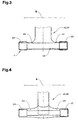
- FIG. 3 and 4 show various examples of clamping elements 1, which are placed on a clamping tongue 42, 44 and on the side projecting arms 43, 43 'in views on that side of the clamping tongues 42, 44, which face the respective other clamping tongue, ie on the Clamping areas 20, 20 '.
- the clamping regions 20, 20 ' are connected to one another by the elongated carrier 10 or are part of the carrier 10.
- the carrier 10 can be simply a material bridge outside the clamping regions 20, 20'.
- the end regions of the carrier 10 are designed on the rear side of the clamping regions 20, 20 'in the manner of a sleeve as fastening elements, eg as in FIG Fig. 2a + b, and are attached to the arms 43, 43 '.
- the elongated support 10 or the material bridge prevents the entire clamping element 1 from being able to come loose from the clamping tongue 42, 44; However, a certain play in the direction of the axis S is possible.
- Fig. 4 shows that the arms 43, 43 'can also be made as a separate component, which is placed on the actual clamping tongue 42, 44.
- Fig. 4 shows an alternative attachment of the clamping member 1 to the arms, namely with attached to the end portions hooks or clips, which engage around the arms in the direction of the axis S and between them.
- Fig. 5-8 show in side view various examples of the design of the clamping elements 1 in the clamping regions 20, 20 '.
- the clamping element 1 'of the second clamping tongue 44 is in all figures a profile with a cavity on the as in Fig. 4 separately designed arm, for example, is formed.
- the hollow profile has an elastically deformable cover layer, which is directed against the clamping element 1 of the first clamping tongue 42 and thus forms the bearing surface of the clamping element 1 '.
- the clamping element 1.1 is from the free Armende forth on both arms 43, 43 'attachable. It has for a tubular, limited elastic carrier 10.
- an inner plate 51 is arranged, which has a spherical cap 52 in its center.
- the arms 43, 43 ' have recesses 53 corresponding to the spherical cap 52 at a corresponding point, the depth of which is slightly smaller than the height of the spherical cap 52.
- the spherical caps 52 are provided positioned in the recesses 53, so that the plate 51 is mounted on the arm 30 via a ball joint.
- the inner plate 51 can thereby adapt in all directions to the bearing surface of a counter-jaw or to a detected object.
- FIG. 5 is additionally on the side facing away from a detected object of the arm 43, 43 'an Anformung 55 shown, which fixes the clamping element 1.1 on the arm in cooperation with a bulge 56 of the tubular support 10.
- clamping element 1.2 corresponds in principle to in Fig. 2a + b shown. It is also from both sides on the arms 43, 43 'attachable and has for this purpose a tubular, limited elastic support 10.
- this support member 10 is a laterally open, for example multi-chambered hollow section 12 is arranged, which forms a pillow-shaped support surface on advantageously oblique supports 13.
- Fig. 6 illustrates that the front surface of the clamping element 1 in the clamping region 20 is adapted to the retained product or the counter element 1 ', although the two clamping tongues 42, 44 meet at an angle in the clamping region 20.
- the front surface in the clamping region 20 therefore extends at an angle to the surface of the actual carrier 10 when force is applied. This is made possible by the flexibility of the clamping element 1 in the clamping region 20, here by the profile divided into chambers 12 and the use of an elastic material. The force distribution is thus uniform and gentle on the product.
- Fig. 6 also shows that the chamber walls 13 form a resistance that makes it difficult to pull the product down.
- clamping element 1.3 consists essentially of a carrier 10, are attached to the two on all sides closed and filled with a liquid flat pad 62, which define the clamping regions 20, 20 '.
- the carrier 10 is fastened to the arms 43, 43 'by fastening elements 32 designed here in the manner of a rail.
- the pillow 62 could also be a flatter Block 63 of an elastically deformable (eg viscoelastic deformable) material can be used ( Fig. 8 ).
Landscapes
- Engineering & Computer Science (AREA)
- Mechanical Engineering (AREA)
- Clamps And Clips (AREA)
- Manipulator (AREA)
- Orthopedics, Nursing, And Contraception (AREA)
Applications Claiming Priority (1)
| Application Number | Priority Date | Filing Date | Title |
|---|---|---|---|
| CH01561/08A CH699689A1 (de) | 2008-10-02 | 2008-10-02 | Klemmelement zum aufsetzen auf eine klemmzunge eines greifers sowie greifer mit einem solchen klemmelement. |
Publications (3)
| Publication Number | Publication Date |
|---|---|
| EP2172407A2 true EP2172407A2 (fr) | 2010-04-07 |
| EP2172407A3 EP2172407A3 (fr) | 2014-06-11 |
| EP2172407B1 EP2172407B1 (fr) | 2015-07-08 |
Family
ID=40260447
Family Applications (1)
| Application Number | Title | Priority Date | Filing Date |
|---|---|---|---|
| EP09405164.6A Not-in-force EP2172407B1 (fr) | 2008-10-02 | 2009-09-22 | Machoire d'une pince et elément de serrage pour être appliqué sur la machoire, et pince dotée d'une telle machoire et d'un tel élément de serrage |
Country Status (6)
| Country | Link |
|---|---|
| US (1) | US8220853B2 (fr) |
| EP (1) | EP2172407B1 (fr) |
| AU (1) | AU2009222542B2 (fr) |
| CA (1) | CA2679783C (fr) |
| CH (1) | CH699689A1 (fr) |
| DK (1) | DK2172407T3 (fr) |
Cited By (2)
| Publication number | Priority date | Publication date | Assignee | Title |
|---|---|---|---|---|
| EP2441717A1 (fr) | 2010-10-13 | 2012-04-18 | Ferag AG | Procédé de fonctionnement d'un dispositif de transport ainsi que dispositif de transport destiné à l'exécution du procédé |
| WO2015121031A1 (fr) * | 2014-02-17 | 2015-08-20 | Khs Gmbh | Élément de protection fixé sans outil pour la protection de bouteilles en verre dans des poches d'étoile |
Families Citing this family (5)
| Publication number | Priority date | Publication date | Assignee | Title |
|---|---|---|---|---|
| USD651625S1 (en) * | 2010-03-03 | 2012-01-03 | Yuyama Mfg. Co., Ltd. | Gripping device |
| USD651225S1 (en) * | 2011-02-03 | 2011-12-27 | Yuyama Mfg. Co., Ltd. | Gripping apparatus |
| USD651626S1 (en) * | 2011-02-03 | 2012-01-03 | Yuyama Mfg. Co., Ltd. | Gripping apparatus |
| FR3023273B1 (fr) * | 2014-07-02 | 2016-08-12 | Serac Group | Installation de transport de recipients |
| US9808936B2 (en) * | 2015-08-03 | 2017-11-07 | Massachusetts Institute Of Technology | Two-phase gripper to reorient and grasp |
Citations (3)
| Publication number | Priority date | Publication date | Assignee | Title |
|---|---|---|---|---|
| DE3102242A1 (de) | 1980-02-08 | 1982-02-04 | Ferag AG, 8340 Hinwil, Zürich | Foerdereinrichtung, insbesondere fuer druckprodukte |
| EP0600183A1 (fr) | 1992-12-02 | 1994-06-08 | Ferag AG | Pince pour transporteur pour transporter des produits imprimés à une ou plusieurs feuilles |
| WO2007115421A1 (fr) | 2006-04-12 | 2007-10-18 | Ferag Ag | Pince destinée à la préhension et au transport d'objets plats |
Family Cites Families (3)
| Publication number | Priority date | Publication date | Assignee | Title |
|---|---|---|---|---|
| ES2087569T3 (es) * | 1992-02-19 | 1996-07-16 | Ferag Ag | Gancho para un dispositivo transportador para el transporte de productos de imprenta de una o varias hojas. |
| US5575379A (en) * | 1993-06-17 | 1996-11-19 | Gammerler Maschinenbau Und Anlagentechnik Gmbh | Newspaper conveyor |
| DE59707897D1 (de) * | 1996-05-09 | 2002-09-12 | Grapha Holding Ag | Verfahren zum Sammeln von Druckprodukten zu Druckerzeugnissen |
-
2008
- 2008-10-02 CH CH01561/08A patent/CH699689A1/de not_active Application Discontinuation
-
2009
- 2009-09-22 DK DK09405164.6T patent/DK2172407T3/en active
- 2009-09-22 EP EP09405164.6A patent/EP2172407B1/fr not_active Not-in-force
- 2009-09-22 CA CA2679783A patent/CA2679783C/fr not_active Expired - Fee Related
- 2009-09-30 AU AU2009222542A patent/AU2009222542B2/en not_active Ceased
- 2009-10-01 US US12/571,817 patent/US8220853B2/en not_active Expired - Fee Related
Patent Citations (3)
| Publication number | Priority date | Publication date | Assignee | Title |
|---|---|---|---|---|
| DE3102242A1 (de) | 1980-02-08 | 1982-02-04 | Ferag AG, 8340 Hinwil, Zürich | Foerdereinrichtung, insbesondere fuer druckprodukte |
| EP0600183A1 (fr) | 1992-12-02 | 1994-06-08 | Ferag AG | Pince pour transporteur pour transporter des produits imprimés à une ou plusieurs feuilles |
| WO2007115421A1 (fr) | 2006-04-12 | 2007-10-18 | Ferag Ag | Pince destinée à la préhension et au transport d'objets plats |
Cited By (3)
| Publication number | Priority date | Publication date | Assignee | Title |
|---|---|---|---|---|
| EP2441717A1 (fr) | 2010-10-13 | 2012-04-18 | Ferag AG | Procédé de fonctionnement d'un dispositif de transport ainsi que dispositif de transport destiné à l'exécution du procédé |
| WO2015121031A1 (fr) * | 2014-02-17 | 2015-08-20 | Khs Gmbh | Élément de protection fixé sans outil pour la protection de bouteilles en verre dans des poches d'étoile |
| US9731912B2 (en) | 2014-02-17 | 2017-08-15 | Khs Gmbh | Container handling arrangement for handling beverage containers, including glass beverage bottles |
Also Published As
| Publication number | Publication date |
|---|---|
| US20100084882A1 (en) | 2010-04-08 |
| CA2679783A1 (fr) | 2010-04-02 |
| US8220853B2 (en) | 2012-07-17 |
| CH699689A1 (de) | 2010-04-15 |
| CA2679783C (fr) | 2018-04-24 |
| AU2009222542B2 (en) | 2015-11-26 |
| EP2172407B1 (fr) | 2015-07-08 |
| DK2172407T3 (en) | 2015-09-21 |
| AU2009222542A1 (en) | 2010-04-22 |
| EP2172407A3 (fr) | 2014-06-11 |
Similar Documents
| Publication | Publication Date | Title |
|---|---|---|
| EP2172407B1 (fr) | Machoire d'une pince et elément de serrage pour être appliqué sur la machoire, et pince dotée d'une telle machoire et d'un tel élément de serrage | |
| DE3885413T2 (de) | Wischerblatt. | |
| DE60000876T2 (de) | Verbesserter greifer zum handhaben von vorformlingen | |
| DE102006017878A1 (de) | Befestigungsclip | |
| DE102008010540A1 (de) | Wischblattanordnung mit Mehrfachbalken | |
| DE3003141A1 (de) | Klemmschelle | |
| WO2002034607A1 (fr) | Dispositif d'accouplement, en particulier pour au moins deux parties ajustables l'une par rapport a l'autre | |
| DE10010934A1 (de) | Kabelhalter zur Befestigung von Kabeln in Fahrzeugen | |
| EP1208305B1 (fr) | Pince pour element de support | |
| EP1959797B1 (fr) | Matelas | |
| DE202010012226U1 (de) | Befestigungseinrichtung | |
| EP1862356B1 (fr) | Clip de fixation | |
| EP2711481A1 (fr) | Elément de fixation pour la fixation de planches de terrasse | |
| DE2548936A1 (de) | Vorrichtung zur schienenbefestigung | |
| EP3960419B1 (fr) | Dispositif de fabrication d'une pièce raccord pour fermeture auto-agrippante selon un procédé de moulage par injection | |
| DE3506073A1 (de) | Seiten- und sattelstegpartie fuer eine brille | |
| DE3030567A1 (de) | Vorrichtung zum verbinden des visiers mit einem sturzhelm | |
| EP0922895A2 (fr) | Dispositif à relier un élément allongé | |
| DE7420451U (de) | Wischblatt fuer einen scheibenwischer | |
| DE102006048474B4 (de) | Abschlussstück | |
| DE102015106599A1 (de) | Windschildvorrichtung | |
| EP1217162B1 (fr) | Dispositif d'étanchéité | |
| DE102020111069A1 (de) | Blattfeder | |
| EP2589281B1 (fr) | Corps de charrue avec un versoir de charrue | |
| DE102009010222A1 (de) | Verbindungsteil und Verbindungsanordnungen zur fluchtenden Verbindung benachbarter Doppelstab-oder Flachstab-oder kombinierter Doppelstab-Flachstab-Gittermatten und damit gebauter Zaun |
Legal Events
| Date | Code | Title | Description |
|---|---|---|---|
| PUAI | Public reference made under article 153(3) epc to a published international application that has entered the european phase |
Free format text: ORIGINAL CODE: 0009012 |
|
| AK | Designated contracting states |
Kind code of ref document: A2 Designated state(s): AT BE BG CH CY CZ DE DK EE ES FI FR GB GR HR HU IE IS IT LI LT LU LV MC MK MT NL NO PL PT RO SE SI SK SM TR |
|
| AX | Request for extension of the european patent |
Extension state: AL BA RS |
|
| REG | Reference to a national code |
Ref country code: DE Ref legal event code: R079 Ref document number: 502009011224 Country of ref document: DE Free format text: PREVIOUS MAIN CLASS: B65H0029040000 Ipc: B65H0029000000 |
|
| PUAL | Search report despatched |
Free format text: ORIGINAL CODE: 0009013 |
|
| RIC1 | Information provided on ipc code assigned before grant |
Ipc: B65H 29/00 20060101AFI20140430BHEP |
|
| AK | Designated contracting states |
Kind code of ref document: A3 Designated state(s): AT BE BG CH CY CZ DE DK EE ES FI FR GB GR HR HU IE IS IT LI LT LU LV MC MK MT NL NO PL PT RO SE SI SK SM TR |
|
| AX | Request for extension of the european patent |
Extension state: AL BA RS |
|
| 17P | Request for examination filed |
Effective date: 20141103 |
|
| RBV | Designated contracting states (corrected) |
Designated state(s): AT BE BG CH CY CZ DE DK EE ES FI FR GB GR HR HU IE IS IT LI LT LU LV MC MK MT NL NO PL PT RO SE SI SK SM TR |
|
| GRAP | Despatch of communication of intention to grant a patent |
Free format text: ORIGINAL CODE: EPIDOSNIGR1 |
|
| INTG | Intention to grant announced |
Effective date: 20150204 |
|
| GRAS | Grant fee paid |
Free format text: ORIGINAL CODE: EPIDOSNIGR3 |
|
| GRAA | (expected) grant |
Free format text: ORIGINAL CODE: 0009210 |
|
| AK | Designated contracting states |
Kind code of ref document: B1 Designated state(s): AT BE BG CH CY CZ DE DK EE ES FI FR GB GR HR HU IE IS IT LI LT LU LV MC MK MT NL NO PL PT RO SE SI SK SM TR |
|
| REG | Reference to a national code |
Ref country code: GB Ref legal event code: FG4D Free format text: NOT ENGLISH |
|
| REG | Reference to a national code |
Ref country code: AT Ref legal event code: REF Ref document number: 735223 Country of ref document: AT Kind code of ref document: T Effective date: 20150715 Ref country code: CH Ref legal event code: EP |
|
| REG | Reference to a national code |
Ref country code: CH Ref legal event code: NV Representative=s name: FREI PATENTANWALTSBUERO AG, CH |
|
| REG | Reference to a national code |
Ref country code: IE Ref legal event code: FG4D Free format text: LANGUAGE OF EP DOCUMENT: GERMAN |
|
| REG | Reference to a national code |
Ref country code: DE Ref legal event code: R096 Ref document number: 502009011224 Country of ref document: DE |
|
| REG | Reference to a national code |
Ref country code: DK Ref legal event code: T3 Effective date: 20150915 |
|
| REG | Reference to a national code |
Ref country code: SE Ref legal event code: TRGR |
|
| REG | Reference to a national code |
Ref country code: NL Ref legal event code: MP Effective date: 20150708 |
|
| REG | Reference to a national code |
Ref country code: LT Ref legal event code: MG4D |
|
| PG25 | Lapsed in a contracting state [announced via postgrant information from national office to epo] |
Ref country code: GR Free format text: LAPSE BECAUSE OF FAILURE TO SUBMIT A TRANSLATION OF THE DESCRIPTION OR TO PAY THE FEE WITHIN THE PRESCRIBED TIME-LIMIT Effective date: 20151009 Ref country code: FI Free format text: LAPSE BECAUSE OF FAILURE TO SUBMIT A TRANSLATION OF THE DESCRIPTION OR TO PAY THE FEE WITHIN THE PRESCRIBED TIME-LIMIT Effective date: 20150708 Ref country code: LT Free format text: LAPSE BECAUSE OF FAILURE TO SUBMIT A TRANSLATION OF THE DESCRIPTION OR TO PAY THE FEE WITHIN THE PRESCRIBED TIME-LIMIT Effective date: 20150708 Ref country code: NO Free format text: LAPSE BECAUSE OF FAILURE TO SUBMIT A TRANSLATION OF THE DESCRIPTION OR TO PAY THE FEE WITHIN THE PRESCRIBED TIME-LIMIT Effective date: 20151008 Ref country code: LV Free format text: LAPSE BECAUSE OF FAILURE TO SUBMIT A TRANSLATION OF THE DESCRIPTION OR TO PAY THE FEE WITHIN THE PRESCRIBED TIME-LIMIT Effective date: 20150708 |
|
| PG25 | Lapsed in a contracting state [announced via postgrant information from national office to epo] |
Ref country code: PT Free format text: LAPSE BECAUSE OF FAILURE TO SUBMIT A TRANSLATION OF THE DESCRIPTION OR TO PAY THE FEE WITHIN THE PRESCRIBED TIME-LIMIT Effective date: 20151109 Ref country code: IS Free format text: LAPSE BECAUSE OF FAILURE TO SUBMIT A TRANSLATION OF THE DESCRIPTION OR TO PAY THE FEE WITHIN THE PRESCRIBED TIME-LIMIT Effective date: 20151108 Ref country code: HR Free format text: LAPSE BECAUSE OF FAILURE TO SUBMIT A TRANSLATION OF THE DESCRIPTION OR TO PAY THE FEE WITHIN THE PRESCRIBED TIME-LIMIT Effective date: 20150708 Ref country code: PL Free format text: LAPSE BECAUSE OF FAILURE TO SUBMIT A TRANSLATION OF THE DESCRIPTION OR TO PAY THE FEE WITHIN THE PRESCRIBED TIME-LIMIT Effective date: 20150708 Ref country code: ES Free format text: LAPSE BECAUSE OF FAILURE TO SUBMIT A TRANSLATION OF THE DESCRIPTION OR TO PAY THE FEE WITHIN THE PRESCRIBED TIME-LIMIT Effective date: 20150708 |
|
| REG | Reference to a national code |
Ref country code: DE Ref legal event code: R097 Ref document number: 502009011224 Country of ref document: DE |
|
| PG25 | Lapsed in a contracting state [announced via postgrant information from national office to epo] |
Ref country code: EE Free format text: LAPSE BECAUSE OF FAILURE TO SUBMIT A TRANSLATION OF THE DESCRIPTION OR TO PAY THE FEE WITHIN THE PRESCRIBED TIME-LIMIT Effective date: 20150708 Ref country code: CZ Free format text: LAPSE BECAUSE OF FAILURE TO SUBMIT A TRANSLATION OF THE DESCRIPTION OR TO PAY THE FEE WITHIN THE PRESCRIBED TIME-LIMIT Effective date: 20150708 Ref country code: SK Free format text: LAPSE BECAUSE OF FAILURE TO SUBMIT A TRANSLATION OF THE DESCRIPTION OR TO PAY THE FEE WITHIN THE PRESCRIBED TIME-LIMIT Effective date: 20150708 Ref country code: LU Free format text: LAPSE BECAUSE OF FAILURE TO SUBMIT A TRANSLATION OF THE DESCRIPTION OR TO PAY THE FEE WITHIN THE PRESCRIBED TIME-LIMIT Effective date: 20150922 Ref country code: IT Free format text: LAPSE BECAUSE OF FAILURE TO SUBMIT A TRANSLATION OF THE DESCRIPTION OR TO PAY THE FEE WITHIN THE PRESCRIBED TIME-LIMIT Effective date: 20150708 Ref country code: MC Free format text: LAPSE BECAUSE OF FAILURE TO SUBMIT A TRANSLATION OF THE DESCRIPTION OR TO PAY THE FEE WITHIN THE PRESCRIBED TIME-LIMIT Effective date: 20150708 |
|
| PLBE | No opposition filed within time limit |
Free format text: ORIGINAL CODE: 0009261 |
|
| STAA | Information on the status of an ep patent application or granted ep patent |
Free format text: STATUS: NO OPPOSITION FILED WITHIN TIME LIMIT |
|
| PG25 | Lapsed in a contracting state [announced via postgrant information from national office to epo] |
Ref country code: RO Free format text: LAPSE BECAUSE OF FAILURE TO SUBMIT A TRANSLATION OF THE DESCRIPTION OR TO PAY THE FEE WITHIN THE PRESCRIBED TIME-LIMIT Effective date: 20150708 |
|
| 26N | No opposition filed |
Effective date: 20160411 |
|
| GBPC | Gb: european patent ceased through non-payment of renewal fee |
Effective date: 20151008 |
|
| REG | Reference to a national code |
Ref country code: IE Ref legal event code: MM4A |
|
| REG | Reference to a national code |
Ref country code: FR Ref legal event code: ST Effective date: 20160531 |
|
| PG25 | Lapsed in a contracting state [announced via postgrant information from national office to epo] |
Ref country code: GB Free format text: LAPSE BECAUSE OF NON-PAYMENT OF DUE FEES Effective date: 20151008 Ref country code: IE Free format text: LAPSE BECAUSE OF NON-PAYMENT OF DUE FEES Effective date: 20150922 |
|
| PG25 | Lapsed in a contracting state [announced via postgrant information from national office to epo] |
Ref country code: FR Free format text: LAPSE BECAUSE OF NON-PAYMENT OF DUE FEES Effective date: 20150930 Ref country code: SI Free format text: LAPSE BECAUSE OF FAILURE TO SUBMIT A TRANSLATION OF THE DESCRIPTION OR TO PAY THE FEE WITHIN THE PRESCRIBED TIME-LIMIT Effective date: 20150708 |
|
| PGFP | Annual fee paid to national office [announced via postgrant information from national office to epo] |
Ref country code: DK Payment date: 20160920 Year of fee payment: 8 |
|
| REG | Reference to a national code |
Ref country code: AT Ref legal event code: MM01 Ref document number: 735223 Country of ref document: AT Kind code of ref document: T Effective date: 20150922 |
|
| PG25 | Lapsed in a contracting state [announced via postgrant information from national office to epo] |
Ref country code: AT Free format text: LAPSE BECAUSE OF NON-PAYMENT OF DUE FEES Effective date: 20150922 |
|
| PG25 | Lapsed in a contracting state [announced via postgrant information from national office to epo] |
Ref country code: MT Free format text: LAPSE BECAUSE OF FAILURE TO SUBMIT A TRANSLATION OF THE DESCRIPTION OR TO PAY THE FEE WITHIN THE PRESCRIBED TIME-LIMIT Effective date: 20150708 |
|
| PG25 | Lapsed in a contracting state [announced via postgrant information from national office to epo] |
Ref country code: BG Free format text: LAPSE BECAUSE OF FAILURE TO SUBMIT A TRANSLATION OF THE DESCRIPTION OR TO PAY THE FEE WITHIN THE PRESCRIBED TIME-LIMIT Effective date: 20150708 Ref country code: SM Free format text: LAPSE BECAUSE OF FAILURE TO SUBMIT A TRANSLATION OF THE DESCRIPTION OR TO PAY THE FEE WITHIN THE PRESCRIBED TIME-LIMIT Effective date: 20150708 Ref country code: HU Free format text: LAPSE BECAUSE OF FAILURE TO SUBMIT A TRANSLATION OF THE DESCRIPTION OR TO PAY THE FEE WITHIN THE PRESCRIBED TIME-LIMIT; INVALID AB INITIO Effective date: 20090922 |
|
| PG25 | Lapsed in a contracting state [announced via postgrant information from national office to epo] |
Ref country code: NL Free format text: LAPSE BECAUSE OF FAILURE TO SUBMIT A TRANSLATION OF THE DESCRIPTION OR TO PAY THE FEE WITHIN THE PRESCRIBED TIME-LIMIT Effective date: 20150708 Ref country code: CY Free format text: LAPSE BECAUSE OF FAILURE TO SUBMIT A TRANSLATION OF THE DESCRIPTION OR TO PAY THE FEE WITHIN THE PRESCRIBED TIME-LIMIT Effective date: 20150708 |
|
| PG25 | Lapsed in a contracting state [announced via postgrant information from national office to epo] |
Ref country code: BE Free format text: LAPSE BECAUSE OF NON-PAYMENT OF DUE FEES Effective date: 20150930 |
|
| PG25 | Lapsed in a contracting state [announced via postgrant information from national office to epo] |
Ref country code: TR Free format text: LAPSE BECAUSE OF FAILURE TO SUBMIT A TRANSLATION OF THE DESCRIPTION OR TO PAY THE FEE WITHIN THE PRESCRIBED TIME-LIMIT Effective date: 20150708 |
|
| PGFP | Annual fee paid to national office [announced via postgrant information from national office to epo] |
Ref country code: SE Payment date: 20170921 Year of fee payment: 9 |
|
| REG | Reference to a national code |
Ref country code: DK Ref legal event code: EBP Effective date: 20170930 |
|
| PG25 | Lapsed in a contracting state [announced via postgrant information from national office to epo] |
Ref country code: MK Free format text: LAPSE BECAUSE OF FAILURE TO SUBMIT A TRANSLATION OF THE DESCRIPTION OR TO PAY THE FEE WITHIN THE PRESCRIBED TIME-LIMIT Effective date: 20150708 |
|
| PGFP | Annual fee paid to national office [announced via postgrant information from national office to epo] |
Ref country code: DE Payment date: 20180920 Year of fee payment: 10 |
|
| PG25 | Lapsed in a contracting state [announced via postgrant information from national office to epo] |
Ref country code: DK Free format text: LAPSE BECAUSE OF NON-PAYMENT OF DUE FEES Effective date: 20170930 |
|
| PGFP | Annual fee paid to national office [announced via postgrant information from national office to epo] |
Ref country code: CH Payment date: 20181128 Year of fee payment: 10 |
|
| REG | Reference to a national code |
Ref country code: SE Ref legal event code: EUG |
|
| PG25 | Lapsed in a contracting state [announced via postgrant information from national office to epo] |
Ref country code: SE Free format text: LAPSE BECAUSE OF NON-PAYMENT OF DUE FEES Effective date: 20180923 |
|
| REG | Reference to a national code |
Ref country code: DE Ref legal event code: R119 Ref document number: 502009011224 Country of ref document: DE |
|
| REG | Reference to a national code |
Ref country code: CH Ref legal event code: PL |
|
| PG25 | Lapsed in a contracting state [announced via postgrant information from national office to epo] |
Ref country code: CH Free format text: LAPSE BECAUSE OF NON-PAYMENT OF DUE FEES Effective date: 20190930 Ref country code: DE Free format text: LAPSE BECAUSE OF NON-PAYMENT OF DUE FEES Effective date: 20200401 Ref country code: LI Free format text: LAPSE BECAUSE OF NON-PAYMENT OF DUE FEES Effective date: 20190930 |