EP0600183A1 - Pince pour transporteur pour transporter des produits imprimés à une ou plusieurs feuilles - Google Patents
Pince pour transporteur pour transporter des produits imprimés à une ou plusieurs feuilles Download PDFInfo
- Publication number
- EP0600183A1 EP0600183A1 EP93115956A EP93115956A EP0600183A1 EP 0600183 A1 EP0600183 A1 EP 0600183A1 EP 93115956 A EP93115956 A EP 93115956A EP 93115956 A EP93115956 A EP 93115956A EP 0600183 A1 EP0600183 A1 EP 0600183A1
- Authority
- EP
- European Patent Office
- Prior art keywords
- gripper
- bearing
- bearing part
- gripper part
- free end
- Prior art date
- Legal status (The legal status is an assumption and is not a legal conclusion. Google has not performed a legal analysis and makes no representation as to the accuracy of the status listed.)
- Granted
Links
- 230000006835 compression Effects 0.000 claims abstract description 19
- 238000007906 compression Methods 0.000 claims abstract description 19
- 239000000047 product Substances 0.000 claims description 26
- 230000005540 biological transmission Effects 0.000 claims description 3
- 230000000903 blocking effect Effects 0.000 claims description 2
- 230000000284 resting effect Effects 0.000 claims description 2
- 239000013589 supplement Substances 0.000 claims description 2
- 230000001960 triggered effect Effects 0.000 claims 1
- 230000002349 favourable effect Effects 0.000 abstract description 2
- 238000000034 method Methods 0.000 description 3
- 238000006073 displacement reaction Methods 0.000 description 2
- 230000003993 interaction Effects 0.000 description 2
- OKTJSMMVPCPJKN-UHFFFAOYSA-N Carbon Chemical compound [C] OKTJSMMVPCPJKN-UHFFFAOYSA-N 0.000 description 1
- 229910052799 carbon Inorganic materials 0.000 description 1
- 238000010276 construction Methods 0.000 description 1
- 230000001419 dependent effect Effects 0.000 description 1
- 238000011161 development Methods 0.000 description 1
- 230000018109 developmental process Effects 0.000 description 1
- 230000000694 effects Effects 0.000 description 1
- 230000002040 relaxant effect Effects 0.000 description 1
Images
Classifications
-
- B—PERFORMING OPERATIONS; TRANSPORTING
- B65—CONVEYING; PACKING; STORING; HANDLING THIN OR FILAMENTARY MATERIAL
- B65H—HANDLING THIN OR FILAMENTARY MATERIAL, e.g. SHEETS, WEBS, CABLES
- B65H29/00—Delivering or advancing articles from machines; Advancing articles to or into piles
- B65H29/003—Delivering or advancing articles from machines; Advancing articles to or into piles by grippers
Definitions
- the present invention relates to a gripper for a conveying device for conveying single- or multi-sheet printed products, such as newspapers, magazines and parts thereof, as well as supplements therefor according to claim 1, with the known grippers of this type, such as those e.g. in DE-A-31 02 242 (and the corresponding US-A-4,381,056), larger clamping forces can be achieved with a compact design.
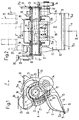
- the grippers 10 shown in the figures have a first gripper part 11, the leg of which is designated by 12, and a second gripper part 13, the leg of which is designated by 14. When the grippers 10 are open, the two gripper parts 11 and 13 define a gripper opening 15.
- the first gripper part 11 can be pivoted with respect to the second gripper part 13 and will be shown in FIGS. 1 and 2 in its closed position, in which its free end 12a and the free end 14a of the second gripper part 13 are used to clamp a printed product (in Figures 1 and 2 not shown) cooperates.
- the second gripper part 13 is formed in one piece with a support part 16 which is pivotally mounted on a hollow shaft 17, the longitudinal axis of which is designated 17 '.
- the shaft 17, which, as can be seen from the figures, is provided with longitudinal grooves, is rotatably mounted in a bracket 18 with a U-shaped cross section, which is fastened to a link chain 19 which is guided in a guide channel 20 (see FIG. 2).
- this endless link chain 19, which is of a known type a large number of grippers 10 are attached at regular intervals, which in a known manner belong to a conveying device for conveying printed products, as described, for example, in EP-A-0 330 868 ( and the corresponding US-A-4,953,847).
- FIG. 1 The conveying direction of this conveying device is shown in FIG. 1 with an arrow denoted by F. As can be seen from this figure 1, the gripper opening 15 points backwards with respect to this conveying direction F.
- a bearing part 21 for the first gripper part 11 is also connected in a rotationally fixed manner to the shaft 17.
- the latter is pivoted and tiltable in this bearing part 21 by means of a ball joint 22 in a manner to be described.
- the ball joint 22 has a socket part 23 formed in the bearing part 21, in which a ball part 24 is held, which is formed at the end of the leg 12 of the first gripper part 11.
- the ball joint 22 is designed in the manner of a snap connection, ie the first gripper part 11 can be pressed with its ball part 24 into the socket part 23 in a simple manner during assembly of the gripper 10.
- the first gripper part 11 can be pivoted on the one hand about an axis 25 which runs essentially parallel to the longitudinal axis 17 'of the carbon shaft 17.
- the first gripper part 11 is pivoted away from or towards the second gripper part 13.
- the spherical mounting of the first gripper part 11 also allows the first gripper part 11 to tilt about a tilt axis 26, which is formed by the longitudinal axis running from the ball joint 22 to the free end 12a of the first gripper part 11, as can be seen in FIG. 2 .
- This possibility of tilting the first gripper part 11 about this tilt axis 26 also allows printed products which have different thicknesses across the width of the gripper 10 to be held securely.
- the latter is arranged between two guide walls 21a, 21b (FIG. 2) formed on the bearing part 21.
- the ball joint 22 is offset from the free end 12a of the first gripper part 11 in relation to the longitudinal axis 17 'of the hollow shaft 17 and thus the pivot axis of the bearing part 21.
- the movable gripper part 11 is mounted outside the actual gripper axis, which is formed by the longitudinal axis 17 'of the hollow shaft 17, which also forms the pivot axis for the second gripper part 13 and thus for the entire gripper 10.
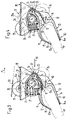
- a compression spring 27 is supported on the bearing part 21 for the first gripper part 11, which is supported at the other end on the leg 12 of the first gripper part 11 and brings this gripper part 11 into contact with the bottom 21c of the bearing part 21 (FIG. 3).
- a rotational movement of the shaft 17 and thus also of the bearing part 21 is transmitted counterclockwise via this compression spring 27 to the first gripper part 11, which does not result in the latter being pivoted out of one in the figures Open position shown in the clamped position, which is shown in Figure 4.
- a locking lever 28 is connected to the shaft 17 in a rotationally fixed manner, the pivot axis of which coincides with the longitudinal axis 17 'of the hollow shaft 17.
- the locking lever 28 carries a follower roller 29 which can be freely rotated.
- this follower roller 29 interacts with the stationary closing link 30, of which a closing link is shown in FIGS. 1, 2 and 3.
- a locking device which has a locking lever 31 which is pivotably mounted on the support part 16.
- This locking lever 31 has at one end a locking lug 32, which cooperates with a locking member 33 for locking the bearing part 21, which is connected at one end to the hollow shaft 17 in a rotationally fixed manner.
- This blocking element 33 is completely visible in FIG. 1 and partially cut away in FIG. 2.
- the locking lever 31 is held in its locked position by means of a spring, not shown.
- the end 31a of the two-armed locking lever 31 opposite the latching lug 32 is intended to cooperate with opening scenes, not shown in the figures, which cause the locking lever 31 to pivot from the locked position into a release position.
- a positioning follower roller 34 is arranged on the support part 16 for the second gripper part 13 on the same side as the locking lever 31 and is freely rotatable. This positioning follower roller 34 interacts with positioning links 35, by means of which the pivot position of the second gripper part 13 and thus of the open and closed gripper 10 is determined. It understands It is clear that the positioning links 35 must be designed in accordance with the respectively desired pivot position of the grippers 10.
- a control cam 36 is provided on the support part 16 for the second gripper part 13 on the side opposite the positioning follower roller 34.
- this control cam 36 By interaction of this control cam 36 with control links, of which a link 37 is shown in FIG. 2, the support part 16 and thus the second gripper part 13 is pivoted into a position which is favorable for the interaction of the positioning follower roller 34 and the stationary positioning link 35.
- This means that the grippers 10 can assume any swivel position outside the area of the product transfer and delivery and that the gripper 10 is then pre-positioned via this control cam 36 and the associated link 37 before the positioning follower roller 34 enters the area of the positioning link 35 reached.
- the rotational movement of the bearing part 21 is transmitted via the compression spring 27 to the leg 12 of the first gripper part 11 without the compression spring 27 being initially tensioned further.
- the first gripper part 11 is thereby pivoted in the direction of the second gripper part 13 and thus against the clamping position. If the closing lever 28 has now reached its position shown in FIG. 3, the free end 12a of the first gripper part 11 comes into contact with the product P to be clamped, which lies on the leg 14 of the second gripper part 13 with the side lying underneath. In this position, the compression spring 27 already exerts a certain clamping force. As can be seen from FIG. 3, the locking member 33 already begins to run onto the locking lug 32 of the locking lever 31.
- the end 12a of the first gripper part 11 moves along an arc of a circle K 1 to the point designated by 1 in FIG.
- the center of the circular arc K1 lies on the longitudinal axis 17 'of the hollow shaft 17 (which is also the pivot axis of the bearing part 21).
- the radius of the circular arc K1 is denoted by R1.
- the first gripper part 11 located in this intermediate position is indicated by dash-dotted lines, the ball joint 22 assuming the position denoted by 1.
- the ball joint 22 ' is moved into the position denoted by 2 in FIG. 5, while the free end 12a of the first gripper part 11 resting on the printed product P initially moves backwards by the distance b into the position likewise denoted by 2.
- This displacement of the free end 12a of the first gripper part 11 exerts a tensile effect on the printed product P which tends to push the printed product a little further into the gripper 10.
- the free end 12a of the first gripper part is then further pivoting the first gripper part 11 along an arc K2 moves, the center of which lies on the pivot axis 25 determined by the ball joint 22 'and whose radius is denoted by R2.
- the end 12a of the first gripper part 11 moves along the circular arc K 1 until this end 12 a strikes a printed product.
- the aforementioned rearward movement of the end 12a of the gripper part 11 is therefore extremely small or practically nonexistent in the case of thin products.
- c denotes the width of the gripper opening 15 that can be used for gripping printed products of different thicknesses.
- the ball joint 22 or the pivot axis 25 of the first clamping part 11 defined thereby is backwards by the distance a with respect to the pivot axis 17 'of the bearing part 21, ie in a direction from the free end 12a of the first Gripper part 11 away, offset.
- an extension of the leg 12 of the first gripper part 11 in the direction away from the line of action 38 (FIG. 5) of the compression spring 27 is obtained.
- the part of the leg 12 lying between the line of application 38 of the compression spring 27 and the free end 12a need not of the first gripper part 11 can be extended, which enables a compact design with the shortest possible gripper legs 12, 14.
- this pivot bearing can be designed as a ball joint 22 which, as explained, enables the first gripper part 11 to tilt somewhat about its longitudinal axis 26 (see FIG. 2).
- the position of the first gripper part 11 can thus be adapted to a printed product P, even if this should have a different thickness over its width. This means that in the area of the free end 12a of the first gripper part 11 there is an essentially equally strong clamping of the printed product P over its entire width d (FIG. 2), even if the latter is unevenly thick. This ensures that the printed products are properly clamped.
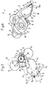
- FIG. 6 shows a gripper 10 which corresponds in construction to the gripper shown in FIGS. 1-4, but which is pivoted into a position in which the gripper opening 15 runs ahead in the direction of movement F of the gripper 10. From the representations of Figures 1 and 6 it can be seen how large the usable swivel range is, i.e. in which different positions the gripper 10 can grasp or deliver printed products.
- a clamping member 39 facing the other gripper part 11 is provided on the second gripper part 13 in the region of its free end 14a and serves to clamp a printed product P '.
- the clamping member 39 has a clamping surface 39a which, when the gripper 10 is closed, lies opposite the end 12a of the gripper part 11 and runs approximately parallel to it.
- the printed product P ' is held between the clamping surface 39a of the clamping member 39 and the free end 12a of the first gripper part 11 in a specific, defined position.
- the displacement of the pivot axis 25 of the first gripper part 11 relative to the pivot axis 17 'of the bearing part 21 provides freedom in the design of the pivot bearing for this first gripper part 11.
- the design of this pivot bearing as a ball joint 22 creates the possibility that the first gripper part 11 can perform a certain tilting movement about its longitudinal axis 26.
- the pivot bearing can also be designed differently to enable the first gripper part 11, in addition to one Pivoting movement about an axis 25 running essentially parallel to the pivot axis 17 'of the bearing part 21 also has to perform a tilting movement about the longitudinal axis 26 of the first gripper part 11, which essentially runs from the pivot bearing 22 to the free end 12a of the first gripper part 11.
- the gripper parts 11 and 13 can be produced from plastic. It is not necessary for the legs 12, 14 of the gripper parts 11, 13 to be very flexible. However, it is now also possible to design at least the leg 12 of the first gripper part 11 as a spiral spring and to arrange an essentially inelastic transmission element on the bearing part 21 instead of the compression spring 27, which is approximately in the direction of the line of action 38 (FIG. 5) on the leg 12 of the acts first gripper part 11 and takes it first and then bends at the end of the closing process described with reference to Figures 3 and 4, so as to generate the desired clamping force at the free end of the first gripper part 11.
Landscapes
- Mechanical Engineering (AREA)
- Engineering & Computer Science (AREA)
- Discharge By Other Means (AREA)
- Supply, Installation And Extraction Of Printed Sheets Or Plates (AREA)
- Intermediate Stations On Conveyors (AREA)
- Attitude Control For Articles On Conveyors (AREA)
- Feeding Of Articles By Means Other Than Belts Or Rollers (AREA)
- Sheets, Magazines, And Separation Thereof (AREA)
- Manipulator (AREA)
- Collation Of Sheets And Webs (AREA)
- Re-Forming, After-Treatment, Cutting And Transporting Of Glass Products (AREA)
- Wrappers (AREA)
- Laminated Bodies (AREA)
- Footwear And Its Accessory, Manufacturing Method And Apparatuses (AREA)
- Ladders (AREA)
- Refuse Collection And Transfer (AREA)
- Specific Conveyance Elements (AREA)
Applications Claiming Priority (2)
| Application Number | Priority Date | Filing Date | Title |
|---|---|---|---|
| CH3694/92 | 1992-12-02 | ||
| CH369492 | 1992-12-02 |
Publications (2)
| Publication Number | Publication Date |
|---|---|
| EP0600183A1 true EP0600183A1 (fr) | 1994-06-08 |
| EP0600183B1 EP0600183B1 (fr) | 1997-05-21 |
Family
ID=4261526
Family Applications (1)
| Application Number | Title | Priority Date | Filing Date |
|---|---|---|---|
| EP93115956A Expired - Lifetime EP0600183B1 (fr) | 1992-12-02 | 1993-10-02 | Pince pour transporteur pour transporter des produits imprimés à une ou plusieurs feuilles |
Country Status (15)
| Country | Link |
|---|---|
| US (1) | US5395151A (fr) |
| EP (1) | EP0600183B1 (fr) |
| JP (1) | JP3333610B2 (fr) |
| KR (1) | KR0136248B1 (fr) |
| AT (1) | ATE153307T1 (fr) |
| AU (1) | AU658770B2 (fr) |
| BR (1) | BR9304907A (fr) |
| CA (1) | CA2110423C (fr) |
| DE (1) | DE59306510D1 (fr) |
| DK (1) | DK0600183T3 (fr) |
| ES (1) | ES2101187T3 (fr) |
| FI (1) | FI111239B (fr) |
| NO (1) | NO180007C (fr) |
| NZ (1) | NZ250324A (fr) |
| RU (1) | RU2077467C1 (fr) |
Cited By (7)
| Publication number | Priority date | Publication date | Assignee | Title |
|---|---|---|---|---|
| WO1995000429A1 (fr) * | 1993-06-17 | 1995-01-05 | Gämmerler Maschinenbau Und Anlagentechnik Gmbh | Convoyeur de journaux |
| EP0709218A1 (fr) | 1994-10-27 | 1996-05-01 | Ferag AG | Procédé et dispositif pour marquer des produits imprimés |
| EP1661833A1 (fr) | 2004-11-26 | 2006-05-31 | Ferag AG | Procédé et dispositif pour traiter des produits imprimés |
| EP2172407A2 (fr) | 2008-10-02 | 2010-04-07 | Ferag AG | Elément de serrage pour l'application sur une machoire d'une pince et pince dotée d'un tel élément de serrage |
| EP2258645A2 (fr) | 2009-06-03 | 2010-12-08 | Ferag AG | Dipsositif et procédé pour le traitement de produits d'impression |
| EP2386512A1 (fr) | 2010-05-10 | 2011-11-16 | Ferag AG | Dispositif et procédé pour transporter des produits plats et souples |
| WO2012034242A1 (fr) | 2010-09-17 | 2012-03-22 | Ferag Ag | Dispositif pour le transfert de produits à un transporteur à griffes |
Families Citing this family (34)
| Publication number | Priority date | Publication date | Assignee | Title |
|---|---|---|---|---|
| DK0631952T3 (da) * | 1993-06-29 | 1998-10-19 | Ferag Ag | Anordning til befordring af produkter, såsom kortog vareprøver til et videreforarbejdningssted |
| US5810347A (en) * | 1994-11-21 | 1998-09-22 | Heidelberger Druckmaschinen Ag | Apparatus for gripping and conveying sheet-like products |
| CA2174076C (fr) * | 1996-04-12 | 2003-03-25 | Sylvain Rodier | Dispositif d'etamage en continu de boitiers dip |
| DE19642117A1 (de) * | 1996-10-12 | 1998-04-16 | Koenig & Bauer Albert Ag | Klemmzange für Endlosförderer |
| DE59704238D1 (de) * | 1997-01-16 | 2001-09-13 | Ferag Ag | Verfahren und Vorrichtung zum Verarbeiten von flächigen Druckereierzeugnissen, wie Zeitungen, Zeitschriften und Teilen hievon |
| DK0870710T3 (da) | 1997-04-07 | 2003-12-08 | Ferag Ag | Fremgangsmåde og indretning til udslusning af trykkeriprodukter fra en transportstrøm og til dannelse af stabler af de udslusede trykkeriprodukter |
| EP0901977B1 (fr) | 1997-09-10 | 2002-10-23 | Ferag AG | Dispositif pour faire tourner des articles arrivant en formation imbriquée |
| AU755468B2 (en) | 1998-06-15 | 2002-12-12 | Ferag Ag | Apparatus for processing flexible, sheet-like products |
| WO2000024660A1 (fr) | 1998-10-26 | 2000-05-04 | Ferag Ag | Procede et dispositif d'alimentation en imprimes |
| US6227588B1 (en) * | 1999-02-17 | 2001-05-08 | Heidelberger Druckmaschinen Aktiengesellschaft | Gripper assembly |
| US6227589B1 (en) | 1999-12-01 | 2001-05-08 | Philadelphia Newspapers, Inc. | Gripper assembly for a conveying device for conveying single-sheet or multi-sheet printed products and a method for modifying the same |
| EP1148007B1 (fr) * | 2000-04-19 | 2003-07-30 | Grapha-Holding AG | Dispositif pour enlever des produits imprimés d'un dispositif de transport sur lequel ils sont régulièrement espacés |
| ATE273229T1 (de) * | 2001-01-24 | 2004-08-15 | Ferag Ag | Verfahren und einrichtung zum umgreifen von mit greifern gehalten geförderten, flachen gegenständen |
| US6705608B2 (en) * | 2002-07-01 | 2004-03-16 | Heidelberger Druckmaschinen Ag | Sheet material conveying apparatus with adjustable top grippers for pockets |
| US6851544B2 (en) * | 2003-05-19 | 2005-02-08 | Graphic Management Associates, Inc. | Transfer device |
| US7055676B2 (en) * | 2003-11-13 | 2006-06-06 | Hartness International, Inc. | Conveyor with movable gripper and related conveyor link |
| US7264113B2 (en) | 2003-11-13 | 2007-09-04 | Hartness International, Inc. | Pivotable conveyor and link |
| US7207434B2 (en) | 2003-11-13 | 2007-04-24 | Hartness International, Inc. | Conveyor with center-actuatable gripper, and related conveyor link |
| US7036658B2 (en) * | 2003-11-13 | 2006-05-02 | Hartness International, Inc. | Gripper conveyor with clear conveying path and related conveyor link |
| US7216758B2 (en) | 2003-11-13 | 2007-05-15 | Hartness International, Inc. | Conveyor with opposed spring-loaded grippers, and related conveyor link |
| US7261199B2 (en) * | 2004-06-29 | 2007-08-28 | Hartness International, Inc. | Neck gripping conveyor and link, and related rotary filler and system |
| US7021453B2 (en) * | 2003-11-13 | 2006-04-04 | Hartness International, Inc. | Conveyor with gear mechanism gripper and related conveyor link |
| US7055677B2 (en) * | 2003-11-13 | 2006-06-06 | Hartness International, Inc. | Conveyor with movable grippers, and related conveyor link |
| US7278531B2 (en) * | 2004-06-29 | 2007-10-09 | Hartness International, Inc. | Flexible conveyor and connection elements |
| US7299832B2 (en) * | 2004-06-29 | 2007-11-27 | Hartness International, Inc. | Rotary filling machine and related components, and related method |
| US7331156B2 (en) * | 2004-06-29 | 2008-02-19 | Hartness International, Inc. | System for securely conveying articles and related components |
| US7185753B2 (en) * | 2004-09-28 | 2007-03-06 | Hartness International, Inc. | Shuttle conveyor |
| CH704642B1 (de) * | 2005-01-21 | 2012-09-28 | Ferag Ag | Vorrichtung zum Beschneiden flexibler, flächiger Produkte. |
| DE102005048754B4 (de) * | 2005-10-10 | 2007-08-23 | Neusser Druckerei Und Verlag Gmbh | Reinigungsapparatur für Greifer eines Transporteursystems für Druckereiprodukte |
| US7530564B2 (en) * | 2006-07-10 | 2009-05-12 | Goss International Americas, Inc. | Opposing link gripper |
| CH704596A1 (de) | 2011-03-10 | 2012-09-14 | Ferag Ag | Reinigungsapparatur für eine Fördereinrichtung. |
| KR101308487B1 (ko) * | 2011-09-01 | 2013-09-25 | 주식회사신도리코 | 사무기기용 용지 고정 장치 |
| IT201900008817A1 (it) * | 2019-06-13 | 2020-12-13 | Gd Spa | Sistema di trasporto per una cartuccia, in particolare per sigaretta elettronica, almeno parzialmente completa. |
| DE102023133829A1 (de) * | 2023-12-04 | 2025-06-05 | Schaeffler Technologies AG & Co. KG | Greifvorrichtung |
Citations (2)
| Publication number | Priority date | Publication date | Assignee | Title |
|---|---|---|---|---|
| US4381056A (en) * | 1980-02-08 | 1983-04-26 | Ferag Ag | Conveyor apparatus, especially for printed products |
| US4953847A (en) * | 1988-03-03 | 1990-09-04 | Ferag Ag | Method of and apparatus for outfeeding printed products arriving in an imbricated formation |
Family Cites Families (14)
| Publication number | Priority date | Publication date | Assignee | Title |
|---|---|---|---|---|
| AU421183B2 (en) * | 1967-08-11 | 1972-02-07 | Miller Printing Machinery Co | Apparatus for handling sheets |
| DE2337210A1 (de) * | 1973-07-21 | 1975-02-06 | Maschf Augsburg Nuernberg Ag | Klemmgreifer fuer bogenverarbeitende, intermittierend foerdernde maschinen, insbesondere druck- und stanzmaschinen |
| CH636824A5 (de) * | 1979-03-08 | 1983-06-30 | Ferag Ag | Foerdereinrichtung fuer flaechige erzeugnisse, insbesondere druckprodukte. |
| EP0287143B1 (fr) * | 1984-09-07 | 1991-07-10 | BELL & HOWELL COMPANY | Pinces avec un détecteur de défectuosités |
| DE3519293A1 (de) * | 1985-05-30 | 1986-12-04 | Koenig & Bauer AG, 8700 Würzburg | Greifersystem |
| US4681213A (en) * | 1985-10-23 | 1987-07-21 | Harris Graphics Corporation | Gripper assembly |
| US4638906A (en) * | 1985-11-19 | 1987-01-27 | Harris Graphics Corporation | Conveyor assembly |
| US4746007A (en) * | 1986-02-20 | 1988-05-24 | Quipp Incorporated | Single gripper conveyor system |
| CH683913A5 (de) * | 1987-10-23 | 1994-06-15 | Ferag Ag | Transporteur für kontinuierlich anfallende Flächengebilde, insbesondere Druckereiprodukte. |
| US4921294A (en) * | 1988-06-03 | 1990-05-01 | Am International Incorporated | Spring wire gripper jaw |
| CH677652A5 (fr) * | 1989-03-07 | 1991-06-14 | Grapha Holding Ag | |
| US4968081A (en) * | 1989-03-13 | 1990-11-06 | Hall Processing Systems | Non-contact actuator |
| JPH04502608A (ja) * | 1989-11-08 | 1992-05-14 | グラファーホールディンク・アーゲー | チェーンコンベヤ用クランプ |
| US5188349A (en) * | 1991-10-07 | 1993-02-23 | Ferag Ag | Method and apparatus for inserting printed products in a folded main product |
-
1993
- 1993-10-02 DE DE59306510T patent/DE59306510D1/de not_active Expired - Lifetime
- 1993-10-02 DK DK93115956.0T patent/DK0600183T3/da active
- 1993-10-02 EP EP93115956A patent/EP0600183B1/fr not_active Expired - Lifetime
- 1993-10-02 AT AT93115956T patent/ATE153307T1/de active
- 1993-10-02 ES ES93115956T patent/ES2101187T3/es not_active Expired - Lifetime
- 1993-10-11 AU AU48940/93A patent/AU658770B2/en not_active Expired
- 1993-11-17 KR KR1019930024523A patent/KR0136248B1/ko not_active Expired - Lifetime
- 1993-11-22 NO NO934222A patent/NO180007C/no not_active IP Right Cessation
- 1993-11-26 JP JP29688493A patent/JP3333610B2/ja not_active Expired - Fee Related
- 1993-11-29 US US08/158,616 patent/US5395151A/en not_active Expired - Lifetime
- 1993-11-30 NZ NZ250324A patent/NZ250324A/en not_active IP Right Cessation
- 1993-12-01 BR BR9304907A patent/BR9304907A/pt not_active IP Right Cessation
- 1993-12-01 RU RU9393053896A patent/RU2077467C1/ru active
- 1993-12-01 CA CA002110423A patent/CA2110423C/fr not_active Expired - Lifetime
- 1993-12-01 FI FI935383A patent/FI111239B/fi not_active IP Right Cessation
Patent Citations (3)
| Publication number | Priority date | Publication date | Assignee | Title |
|---|---|---|---|---|
| US4381056A (en) * | 1980-02-08 | 1983-04-26 | Ferag Ag | Conveyor apparatus, especially for printed products |
| US4381056B1 (fr) * | 1980-02-08 | 1989-07-25 | ||
| US4953847A (en) * | 1988-03-03 | 1990-09-04 | Ferag Ag | Method of and apparatus for outfeeding printed products arriving in an imbricated formation |
Cited By (11)
| Publication number | Priority date | Publication date | Assignee | Title |
|---|---|---|---|---|
| WO1995000429A1 (fr) * | 1993-06-17 | 1995-01-05 | Gämmerler Maschinenbau Und Anlagentechnik Gmbh | Convoyeur de journaux |
| US5575379A (en) * | 1993-06-17 | 1996-11-19 | Gammerler Maschinenbau Und Anlagentechnik Gmbh | Newspaper conveyor |
| EP0709218A1 (fr) | 1994-10-27 | 1996-05-01 | Ferag AG | Procédé et dispositif pour marquer des produits imprimés |
| EP1661833A1 (fr) | 2004-11-26 | 2006-05-31 | Ferag AG | Procédé et dispositif pour traiter des produits imprimés |
| EP2172407A2 (fr) | 2008-10-02 | 2010-04-07 | Ferag AG | Elément de serrage pour l'application sur une machoire d'une pince et pince dotée d'un tel élément de serrage |
| US8220853B2 (en) | 2008-10-02 | 2012-07-17 | Ferag Ag | Clamping element for fitting on a clamping tongue of a gripper as well as gripper fitted with such a clamping element |
| EP2258645A2 (fr) | 2009-06-03 | 2010-12-08 | Ferag AG | Dipsositif et procédé pour le traitement de produits d'impression |
| US8777221B2 (en) | 2009-06-03 | 2014-07-15 | Ferag Ab | Device and method for processing printing products |
| EP2386512A1 (fr) | 2010-05-10 | 2011-11-16 | Ferag AG | Dispositif et procédé pour transporter des produits plats et souples |
| US8550460B2 (en) | 2010-05-10 | 2013-10-08 | Ferag Ag | Apparatus and method for transporting flexible, planar products |
| WO2012034242A1 (fr) | 2010-09-17 | 2012-03-22 | Ferag Ag | Dispositif pour le transfert de produits à un transporteur à griffes |
Also Published As
| Publication number | Publication date |
|---|---|
| FI935383A7 (fi) | 1994-06-03 |
| DK0600183T3 (da) | 1997-10-27 |
| NO180007B (no) | 1996-10-21 |
| US5395151A (en) | 1995-03-07 |
| ES2101187T3 (es) | 1997-07-01 |
| NZ250324A (en) | 1995-09-26 |
| KR0136248B1 (ko) | 1998-04-30 |
| FI111239B (fi) | 2003-06-30 |
| RU2077467C1 (ru) | 1997-04-20 |
| NO934222L (no) | 1994-06-03 |
| JPH06210832A (ja) | 1994-08-02 |
| JP3333610B2 (ja) | 2002-10-15 |
| AU4894093A (en) | 1994-06-16 |
| KR950013942A (ko) | 1995-06-15 |
| NO934222D0 (no) | 1993-11-22 |
| DE59306510D1 (de) | 1997-06-26 |
| NO180007C (no) | 1997-01-29 |
| BR9304907A (pt) | 1994-06-07 |
| ATE153307T1 (de) | 1997-06-15 |
| CA2110423A1 (fr) | 1994-06-03 |
| CA2110423C (fr) | 1999-09-14 |
| FI935383A0 (fi) | 1993-12-01 |
| EP0600183B1 (fr) | 1997-05-21 |
| AU658770B2 (en) | 1995-04-27 |
Similar Documents
| Publication | Publication Date | Title |
|---|---|---|
| EP0600183B1 (fr) | Pince pour transporteur pour transporter des produits imprimés à une ou plusieurs feuilles | |
| DE69302333T2 (de) | Zange mit beweglichen Backen zum Greifen von Flaschen oder dergleichen, vorzugsweise für automatische Spül-/Sterilisiermaschinen | |
| EP0557680B1 (fr) | Pince pour transporteur pour transporter des produits imprimés à une ou plusieurs feuilles | |
| EP0664256B1 (fr) | Outil de tension et de fermeture pour encercler un objet avec une bande thermoplastique | |
| DE69718447T2 (de) | Zahnbürste mit einem entgegen einer federkraft beweglichen bürstenhalter | |
| AT392667B (de) | Weitwinkel-scharnier | |
| EP0823223B1 (fr) | Boucle stabilisée pour ceinture de sécurité à prétendeur | |
| EP3964461B1 (fr) | Dispositif de serrage permettant de maintenir un récipient et dispositif de manutention de récipients | |
| EP0272469B1 (fr) | Pinces pour une machine à imprimer | |
| EP0557679B1 (fr) | Pince pour transporter des produits imprimés à une ou plusieurs feuilles | |
| DE2541990B2 (de) | Übernahmegreifer fur Webmaschinen | |
| EP1413398B1 (fr) | Dispositif de fixation rapide avec mécanisme de blocage | |
| DE10323171B4 (de) | Schweißkopf für eine Bandumreifungsmaschine | |
| DE68915452T2 (de) | Bogentransportvorrichtung mit greifer. | |
| DE4123476A1 (de) | Folienreckmaschine zum schrumpfen von folien | |
| DE2753637C3 (de) | Bewegliche Fadenklemme | |
| DE69313490T2 (de) | Greiferförderer | |
| DE69614443T2 (de) | Werkzeug zum Klemmen von Laufschienen auf Schubladen | |
| DE4036882C1 (en) | Holding clamp for flat objects etc. - has clamp shank(s) with holding arm integrally coupled to stop arm with junction at transition point | |
| EP0931010B1 (fr) | Pince de serrage pour convoyeur sans fin | |
| EP0301244A1 (fr) | Dispositif pour insérer au moins un supplément dans des imprimés | |
| EP0767125A1 (fr) | Pince pour des articles plats | |
| EP1040065B1 (fr) | Pince pour tenir des objets plans | |
| CH690301A5 (de) | Klammer und Transportvorrichtung für flächige Gegenstände. | |
| DE19604562A1 (de) | Bogenleitvorrichtung für Druckmaschinen |
Legal Events
| Date | Code | Title | Description |
|---|---|---|---|
| PUAI | Public reference made under article 153(3) epc to a published international application that has entered the european phase |
Free format text: ORIGINAL CODE: 0009012 |
|
| AK | Designated contracting states |
Kind code of ref document: A1 Designated state(s): AT BE CH DE DK ES FR GB IT LI NL SE |
|
| 17P | Request for examination filed |
Effective date: 19940610 |
|
| 17Q | First examination report despatched |
Effective date: 19950905 |
|
| GRAG | Despatch of communication of intention to grant |
Free format text: ORIGINAL CODE: EPIDOS AGRA |
|
| GRAH | Despatch of communication of intention to grant a patent |
Free format text: ORIGINAL CODE: EPIDOS IGRA |
|
| GRAH | Despatch of communication of intention to grant a patent |
Free format text: ORIGINAL CODE: EPIDOS IGRA |
|
| GRAA | (expected) grant |
Free format text: ORIGINAL CODE: 0009210 |
|
| AK | Designated contracting states |
Kind code of ref document: B1 Designated state(s): AT BE CH DE DK ES FR GB IT LI NL SE |
|
| REF | Corresponds to: |
Ref document number: 153307 Country of ref document: AT Date of ref document: 19970615 Kind code of ref document: T |
|
| ITF | It: translation for a ep patent filed | ||
| REG | Reference to a national code |
Ref country code: CH Ref legal event code: NV Representative=s name: PATENTANWAELTE SCHAAD, BALASS, MENZL & PARTNER AG Ref country code: CH Ref legal event code: EP |
|
| GBT | Gb: translation of ep patent filed (gb section 77(6)(a)/1977) |
Effective date: 19970522 |
|
| REF | Corresponds to: |
Ref document number: 59306510 Country of ref document: DE Date of ref document: 19970626 |
|
| REG | Reference to a national code |
Ref country code: ES Ref legal event code: FG2A Ref document number: 2101187 Country of ref document: ES Kind code of ref document: T3 |
|
| ET | Fr: translation filed | ||
| REG | Reference to a national code |
Ref country code: DK Ref legal event code: T3 |
|
| PLBE | No opposition filed within time limit |
Free format text: ORIGINAL CODE: 0009261 |
|
| STAA | Information on the status of an ep patent application or granted ep patent |
Free format text: STATUS: NO OPPOSITION FILED WITHIN TIME LIMIT |
|
| 26N | No opposition filed | ||
| REG | Reference to a national code |
Ref country code: GB Ref legal event code: IF02 |
|
| REG | Reference to a national code |
Ref country code: CH Ref legal event code: PFA Owner name: FERAG AG Free format text: FERAG AG#ZUERICHSTRASSE 74#CH-8340 HINWIL (CH) -TRANSFER TO- FERAG AG#PATENTABTEILUNG Z. H. MARKUS FELIX ZUERICHSTRASSE 74#8340 HINWIL (CH) |
|
| PGFP | Annual fee paid to national office [announced via postgrant information from national office to epo] |
Ref country code: DK Payment date: 20121022 Year of fee payment: 20 |
|
| PGFP | Annual fee paid to national office [announced via postgrant information from national office to epo] |
Ref country code: DE Payment date: 20121023 Year of fee payment: 20 Ref country code: CH Payment date: 20121227 Year of fee payment: 20 Ref country code: BE Payment date: 20121022 Year of fee payment: 20 Ref country code: FR Payment date: 20121031 Year of fee payment: 20 |
|
| PGFP | Annual fee paid to national office [announced via postgrant information from national office to epo] |
Ref country code: IT Payment date: 20121026 Year of fee payment: 20 Ref country code: SE Payment date: 20121019 Year of fee payment: 20 Ref country code: GB Payment date: 20121019 Year of fee payment: 20 Ref country code: ES Payment date: 20121026 Year of fee payment: 20 |
|
| PGFP | Annual fee paid to national office [announced via postgrant information from national office to epo] |
Ref country code: NL Payment date: 20121019 Year of fee payment: 20 Ref country code: AT Payment date: 20121011 Year of fee payment: 20 |
|
| REG | Reference to a national code |
Ref country code: DE Ref legal event code: R071 Ref document number: 59306510 Country of ref document: DE |
|
| REG | Reference to a national code |
Ref country code: DE Ref legal event code: R071 Ref document number: 59306510 Country of ref document: DE |
|
| REG | Reference to a national code |
Ref country code: DK Ref legal event code: EUP Effective date: 20131002 Ref country code: DK Ref legal event code: EUP |
|
| REG | Reference to a national code |
Ref country code: NL Ref legal event code: V4 Effective date: 20131002 |
|
| REG | Reference to a national code |
Ref country code: CH Ref legal event code: PL |
|
| REG | Reference to a national code |
Ref country code: GB Ref legal event code: PE20 Expiry date: 20131001 |
|
| BE20 | Be: patent expired |
Owner name: *FERAG A.G. Effective date: 20131002 |
|
| REG | Reference to a national code |
Ref country code: AT Ref legal event code: MK07 Ref document number: 153307 Country of ref document: AT Kind code of ref document: T Effective date: 20131002 |
|
| PG25 | Lapsed in a contracting state [announced via postgrant information from national office to epo] |
Ref country code: GB Free format text: LAPSE BECAUSE OF EXPIRATION OF PROTECTION Effective date: 20131001 |
|
| REG | Reference to a national code |
Ref country code: SE Ref legal event code: EUG |
|
| PG25 | Lapsed in a contracting state [announced via postgrant information from national office to epo] |
Ref country code: DE Free format text: LAPSE BECAUSE OF EXPIRATION OF PROTECTION Effective date: 20131003 |
|
| REG | Reference to a national code |
Ref country code: ES Ref legal event code: FD2A Effective date: 20140925 |
|
| PG25 | Lapsed in a contracting state [announced via postgrant information from national office to epo] |
Ref country code: ES Free format text: LAPSE BECAUSE OF EXPIRATION OF PROTECTION Effective date: 20131003 |