EP2173501B1 - Procédé de fabrication d'un tube plat - Google Patents
Procédé de fabrication d'un tube plat Download PDFInfo
- Publication number
- EP2173501B1 EP2173501B1 EP09713106A EP09713106A EP2173501B1 EP 2173501 B1 EP2173501 B1 EP 2173501B1 EP 09713106 A EP09713106 A EP 09713106A EP 09713106 A EP09713106 A EP 09713106A EP 2173501 B1 EP2173501 B1 EP 2173501B1
- Authority
- EP
- European Patent Office
- Prior art keywords
- flat tube
- projections
- flat
- inner insert
- narrow sides
- Prior art date
- Legal status (The legal status is an assumption and is not a legal conclusion. Google has not performed a legal analysis and makes no representation as to the accuracy of the status listed.)
- Not-in-force
Links
Images



Classifications
-
- B—PERFORMING OPERATIONS; TRANSPORTING
- B21—MECHANICAL METAL-WORKING WITHOUT ESSENTIALLY REMOVING MATERIAL; PUNCHING METAL
- B21C—MANUFACTURE OF METAL SHEETS, WIRE, RODS, TUBES, PROFILES OR LIKE SEMI-MANUFACTURED PRODUCTS OTHERWISE THAN BY ROLLING; AUXILIARY OPERATIONS USED IN CONNECTION WITH METAL-WORKING WITHOUT ESSENTIALLY REMOVING MATERIAL
- B21C37/00—Manufacture of metal sheets, rods, wire, tubes, profiles or like semi-manufactured products, not otherwise provided for; Manufacture of tubes of special shape
- B21C37/06—Manufacture of metal sheets, rods, wire, tubes, profiles or like semi-manufactured products, not otherwise provided for; Manufacture of tubes of special shape of tubes or metal hoses; Combined procedures for making tubes, e.g. for making multi-wall tubes
- B21C37/15—Making tubes of special shape; Making tube fittings
- B21C37/22—Making finned or ribbed tubes by fixing strip or like material to tubes
-
- B—PERFORMING OPERATIONS; TRANSPORTING
- B21—MECHANICAL METAL-WORKING WITHOUT ESSENTIALLY REMOVING MATERIAL; PUNCHING METAL
- B21C—MANUFACTURE OF METAL SHEETS, WIRE, RODS, TUBES, PROFILES OR LIKE SEMI-MANUFACTURED PRODUCTS OTHERWISE THAN BY ROLLING; AUXILIARY OPERATIONS USED IN CONNECTION WITH METAL-WORKING WITHOUT ESSENTIALLY REMOVING MATERIAL
- B21C37/00—Manufacture of metal sheets, rods, wire, tubes, profiles or like semi-manufactured products, not otherwise provided for; Manufacture of tubes of special shape
- B21C37/06—Manufacture of metal sheets, rods, wire, tubes, profiles or like semi-manufactured products, not otherwise provided for; Manufacture of tubes of special shape of tubes or metal hoses; Combined procedures for making tubes, e.g. for making multi-wall tubes
- B21C37/08—Making tubes with welded or soldered seams
- B21C37/087—Making tubes with welded or soldered seams using rods or strips of soldering material
-
- B—PERFORMING OPERATIONS; TRANSPORTING
- B23—MACHINE TOOLS; METAL-WORKING NOT OTHERWISE PROVIDED FOR
- B23K—SOLDERING OR UNSOLDERING; WELDING; CLADDING OR PLATING BY SOLDERING OR WELDING; CUTTING BY APPLYING HEAT LOCALLY, e.g. FLAME CUTTING; WORKING BY LASER BEAM
- B23K1/00—Soldering, e.g. brazing, or unsoldering
- B23K1/0008—Soldering, e.g. brazing, or unsoldering specially adapted for particular articles or work
- B23K1/0012—Brazing of heat exchangers
-
- B—PERFORMING OPERATIONS; TRANSPORTING
- B23—MACHINE TOOLS; METAL-WORKING NOT OTHERWISE PROVIDED FOR
- B23K—SOLDERING OR UNSOLDERING; WELDING; CLADDING OR PLATING BY SOLDERING OR WELDING; CUTTING BY APPLYING HEAT LOCALLY, e.g. FLAME CUTTING; WORKING BY LASER BEAM
- B23K1/00—Soldering, e.g. brazing, or unsoldering
- B23K1/008—Soldering within a furnace
-
- B—PERFORMING OPERATIONS; TRANSPORTING
- B23—MACHINE TOOLS; METAL-WORKING NOT OTHERWISE PROVIDED FOR
- B23K—SOLDERING OR UNSOLDERING; WELDING; CLADDING OR PLATING BY SOLDERING OR WELDING; CUTTING BY APPLYING HEAT LOCALLY, e.g. FLAME CUTTING; WORKING BY LASER BEAM
- B23K1/00—Soldering, e.g. brazing, or unsoldering
- B23K1/20—Preliminary treatment of work or areas to be soldered, e.g. in respect of a galvanic coating
-
- F—MECHANICAL ENGINEERING; LIGHTING; HEATING; WEAPONS; BLASTING
- F28—HEAT EXCHANGE IN GENERAL
- F28D—HEAT-EXCHANGE APPARATUS, NOT PROVIDED FOR IN ANOTHER SUBCLASS, IN WHICH THE HEAT-EXCHANGE MEDIA DO NOT COME INTO DIRECT CONTACT
- F28D1/00—Heat-exchange apparatus having stationary conduit assemblies for one heat-exchange medium only, the media being in contact with different sides of the conduit wall, in which the other heat-exchange medium is a large body of fluid, e.g. domestic or motor car radiators
- F28D1/02—Heat-exchange apparatus having stationary conduit assemblies for one heat-exchange medium only, the media being in contact with different sides of the conduit wall, in which the other heat-exchange medium is a large body of fluid, e.g. domestic or motor car radiators with heat-exchange conduits immersed in the body of fluid
- F28D1/03—Heat-exchange apparatus having stationary conduit assemblies for one heat-exchange medium only, the media being in contact with different sides of the conduit wall, in which the other heat-exchange medium is a large body of fluid, e.g. domestic or motor car radiators with heat-exchange conduits immersed in the body of fluid with plate-like or laminated conduits
- F28D1/0391—Heat-exchange apparatus having stationary conduit assemblies for one heat-exchange medium only, the media being in contact with different sides of the conduit wall, in which the other heat-exchange medium is a large body of fluid, e.g. domestic or motor car radiators with heat-exchange conduits immersed in the body of fluid with plate-like or laminated conduits a single plate being bent to form one or more conduits
-
- F—MECHANICAL ENGINEERING; LIGHTING; HEATING; WEAPONS; BLASTING
- F28—HEAT EXCHANGE IN GENERAL
- F28F—DETAILS OF HEAT-EXCHANGE AND HEAT-TRANSFER APPARATUS, OF GENERAL APPLICATION
- F28F3/00—Plate-like or laminated elements; Assemblies of plate-like or laminated elements
- F28F3/02—Elements or assemblies thereof with means for increasing heat-transfer area, e.g. with fins, with recesses, with corrugations
- F28F3/025—Elements or assemblies thereof with means for increasing heat-transfer area, e.g. with fins, with recesses, with corrugations the means being corrugated, plate-like elements
-
- B—PERFORMING OPERATIONS; TRANSPORTING
- B23—MACHINE TOOLS; METAL-WORKING NOT OTHERWISE PROVIDED FOR
- B23K—SOLDERING OR UNSOLDERING; WELDING; CLADDING OR PLATING BY SOLDERING OR WELDING; CUTTING BY APPLYING HEAT LOCALLY, e.g. FLAME CUTTING; WORKING BY LASER BEAM
- B23K2101/00—Articles made by soldering, welding or cutting
- B23K2101/04—Tubular or hollow articles
- B23K2101/14—Heat exchangers
-
- Y—GENERAL TAGGING OF NEW TECHNOLOGICAL DEVELOPMENTS; GENERAL TAGGING OF CROSS-SECTIONAL TECHNOLOGIES SPANNING OVER SEVERAL SECTIONS OF THE IPC; TECHNICAL SUBJECTS COVERED BY FORMER USPC CROSS-REFERENCE ART COLLECTIONS [XRACs] AND DIGESTS
- Y10—TECHNICAL SUBJECTS COVERED BY FORMER USPC
- Y10T—TECHNICAL SUBJECTS COVERED BY FORMER US CLASSIFICATION
- Y10T29/00—Metal working
- Y10T29/49—Method of mechanical manufacture
- Y10T29/4935—Heat exchanger or boiler making
- Y10T29/49377—Tube with heat transfer means
- Y10T29/49378—Finned tube
- Y10T29/49384—Internally finned
-
- Y—GENERAL TAGGING OF NEW TECHNOLOGICAL DEVELOPMENTS; GENERAL TAGGING OF CROSS-SECTIONAL TECHNOLOGIES SPANNING OVER SEVERAL SECTIONS OF THE IPC; TECHNICAL SUBJECTS COVERED BY FORMER USPC CROSS-REFERENCE ART COLLECTIONS [XRACs] AND DIGESTS
- Y10—TECHNICAL SUBJECTS COVERED BY FORMER USPC
- Y10T—TECHNICAL SUBJECTS COVERED BY FORMER US CLASSIFICATION
- Y10T29/00—Metal working
- Y10T29/49—Method of mechanical manufacture
- Y10T29/4935—Heat exchanger or boiler making
- Y10T29/49391—Tube making or reforming
-
- Y—GENERAL TAGGING OF NEW TECHNOLOGICAL DEVELOPMENTS; GENERAL TAGGING OF CROSS-SECTIONAL TECHNOLOGIES SPANNING OVER SEVERAL SECTIONS OF THE IPC; TECHNICAL SUBJECTS COVERED BY FORMER USPC CROSS-REFERENCE ART COLLECTIONS [XRACs] AND DIGESTS
- Y10—TECHNICAL SUBJECTS COVERED BY FORMER USPC
- Y10T—TECHNICAL SUBJECTS COVERED BY FORMER US CLASSIFICATION
- Y10T29/00—Metal working
- Y10T29/49—Method of mechanical manufacture
- Y10T29/4935—Heat exchanger or boiler making
- Y10T29/49393—Heat exchanger or boiler making with metallurgical bonding
Definitions
- the invention relates to a method for producing flat tubes for heat exchangers, having the features of the preamble of claim 1.
- the heat exchanger from the DE 199 27 607A1 has been specially designed as a charge air cooler and therefore consists of aluminum sheets.
- the ends of the flat tubes have been widened with the flared ends in a stack of flat tubes closely adjacent to each other. Because of the contiguous, end-side widening also arise channels between the flat tubes through which a coolant can flow. Accordingly, it is provided in the publication to dispense with the use of tube sheets. The widenings of the flat tube ends are directly connected and an air box is arranged around the end circumference of the stack.
- the preamble of claim 1 is based on this document.
- the heat exchanger has, in spite of the mentioned end-side widening, additionally tube plates with openings for receiving the pipe ends.
- the flat tube is usually produced on a roller mill or the like endless from the belt and cut to length.
- the flat tube is then deformed in the elastic region, that is, brought in the direction of a slightly elliptical cross section, to facilitate the insertion of the inner liner.
- the tolerances of the inner inserts and the flat tubes must be very close together because of the subsequent soldering, which increases the difficulties.
- the flat tubes 1 with inner inserts 2 described below in the exemplary embodiments are intended for exhaust gas heat exchangers. Therefore, the flat tubes 1 and the inner inserts 2 are made of stainless steel sheets.
- a brazing method is provided in which the inner inserts 2 are to be soldered into the flat tubes 1, is also described as solder foils 30 in the flat tube 1, between the inner liner 2 and the inside of the flat tube wall to be introduced.
- solder coating in stainless steel sheets is currently not solved or at least difficult.
- the outlet strip is an endless belt made of stainless steel sheet. From this coil C is cyclically withdrawn a required piece of sheet metal and fed to a punch S.
- the board P produced in the punching tool represents the tube wall of the later flat tube. In the preferred case (FIG. Fig. 1 ), the board P at one end two projections 4 . This one end is also the later one end of the flat tube 1.
- projections 4 are not essential. At any rate, they would mean extra work.
- the two projections 4 extend in the case shown approximately over both broad sides 11.
- the three cutouts 40 are therefore approximately in the later narrow sides 12 of the flat tube 1.
- the board P leaves the punching tool and can be supplied to another device in which the flat tube shape is produced.
- the flat tube 1 is produced with a minimized welding gap 16 in a narrow side 12 . Following this, the projections 4 can be bent by means of a bending tool.
- the bending angle can be approximately at 35 - 45 °.
- the flat tube with the bent projections 4 is transported to another device.
- the aforementioned punch S or press is a more complex sheet metal forming machine B (in Fig. 1 framed) has been removed, from which the deformed flat tubes 1 run out cyclically with the bent projections 4 .
- the Blechumformstrom B contains at least one tool W for producing the flat tube form of the board P. So in the preferred embodiment, the bending of the projections 4 already takes place in the course of manufacturing the flat tube shape, that is, before welding the longitudinal seam.
- Such complex Blechumformanlagen are known per se, that is, except the integrated therein device V for bending the projections 4.
- the flat tube 1 When bending the projections 4 , the flat tube 1 may still be clamped in the tool W. In this state, the device V approaches one end of the flat tube 1 and guides the Bending process off.
- the respectively achieved processing state of the flat tube was in the Fig. 1 outlined below stations S, W and V. In this case, the flat tube 1 is subsequently transported to a welding station. ( Fig. 2 )
- a welding pad 50 is inserted into the flat tube 1 and in one of the narrow sides 12 of the flat tube 1, a weld 15 is made in the longitudinal direction of the flat tube 1. It can be a laser welded seam.
- the flat tube is held between clamping jaws.
- inner inserts 2 On a second transport route inner inserts 2, also originating from an endless belt, correspondingly formed, that is provided with a wave structure, cut to length and brought to another device.
- an inner insert 2 is inserted into each flat tube 1 .
- the flat tube 1 is oriented so that it comes with its bent projections 4, which serve as chamfers 3 , to lie in the direction of an incoming inner insert 2 .
- the inner insert 2 is brought to the end of the flat tube 1 and pushed into the flat tube 1 into it.
- a view of a flat tube end, which shows the now reached state, is located in the Fig. 6 , As has already been explained in the introduction to this section, in the embodiment shown, however, it is flat tubes 1 and inner inserts 2 made of stainless steel.
- solder foil device LV By means of the solder foil device LV , a piece of solder foil 30 of required length is separated from an endless solder foil strip and brought to it before insertion of the inner insert 2 , so that the solder foil 30 rests on top and bottom of the inner insert 2 . Only then is the insertion of the inner insert 2 together with the solder foil 30.
- the three representations in the Fig. 4 indicate (from top to bottom) how the solder sheet 30 is brought in front of the inner liner 2, is placed around it, and finally as the solder sheet 30 is pushed to the inner insert 2 in the flat tube. 1
- the corrugated inner insert 2 may have in the longitudinal direction of the flat tube 1 running meandering channels 20 , which the sketched representation of the inner insert 2 in the Fig. 4 to explain.
- FIGS. 5 and 6 show the state reached now.
- the individual flat tubes 1 are transported with the inner inserts 2 arranged therein to a separating device in which the bent two projections 4 are removed.
- a tool Wz is inserted into the flat tube end to support it, and thereafter the two projections 4 are cut by means of cutting blades S which engage from the outside.
- the flat tubes 1 equipped with inner inserts 2 are stacked alternately with turbulence plates Tb .
- the resulting cooling network can be soldered in a soldering oven under vacuum, including the cooling network is loaded surface with a contact pressure.
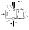
- FIG. 8 shows a small section of a heat exchanger consisting of only two flat tube ends and a tube plate Rb with openings 10, in which the flat tube ends are to be used. It can be seen that an external chamfer 13 has been formed by separating the bent projections 4 , which somewhat facilitates the insertion of the flat tube ends into the openings 10 . Necessary pretreatments with respect to soldering, such as degreasing, etc. are not described, because to the knowledge of the skilled person can be assumed. A housing can now be arranged around the soldered cooling network. This can be welded at the edges of the tube sheets. Furthermore, collection boxes can be attached to the tube sheets and also welded.
- Plastic collection boxes which are mechanically connected to the edges of the tubesheet, are also possible depending on the prevailing temperatures. Existence of the collecting boxes made of metal, it may also be cheaper to attach the housing and the manifolds before soldering the cooling network to the same and only then to solder the entire heat exchanger in the soldering oven. Since the housing is not in contact with the aggressive exhaust gases, it may for example be made of aluminum or ferritic steel. A feasible but not shown because not preferred variant of Flachrohrher ein is to punch out the board P without the mentioned projections 4 . After welding the flat tube described above, the two narrow sides 12 are then cut approximately 4 mm deep or wide at one end of the flat tube 1 . Subsequently, the broad sides 11 are bent approximately 45 ° to the outside. It seems clear that the cutting and the turning off can also be performed by a common tool in one operation. In a currently regarded as not so cheap alternative cuts out the broadsides and turns the narrow sides to the outside. The subsequent operations coincide with those already described above.
Landscapes
- Engineering & Computer Science (AREA)
- Mechanical Engineering (AREA)
- Physics & Mathematics (AREA)
- Thermal Sciences (AREA)
- General Engineering & Computer Science (AREA)
- Heat-Exchange Devices With Radiators And Conduit Assemblies (AREA)
- Rigid Pipes And Flexible Pipes (AREA)
- Bending Of Plates, Rods, And Pipes (AREA)
Claims (7)
- Procédé de fabrication de tubes plats (1) comprenant des inserts internes (2) pour échangeur de chaleur, la paroi de chaque tube plat étant fabriquée sous forme de platine (P) à partir d'un ruban de tôle, étant façonnée pour donner un tube plat présentant des côtés étroits et larges (11, 12), et étant connectée au niveau d'un joint (15), caractérisé en ce que des sections (40) sont produites, lesquelles conduisent à au moins deux saillies (4) à l'extrémité du tube plat et en ce que les saillies (4) sont recourbées vers l'extérieur, de sorte que des biseaux d'insertion (3) soient fournis pour l'insertion de l'insert interne (2) dans chaque tube plat (1), les saillies recourbées (4) étant séparées après l'insertion de l'insert interne (2).
- Procédé selon la revendication 1, caractérisé en ce que la production des saillies (4) a lieu par le fait que la platine (P) est estampée avec au moins trois sections (40) et en ce que la platine (P) est façonnée pour donner un tube plat de telle sorte que les saillies (4) forment au moins des parties des côtés larges (11) ou des côtés étroits (12).
- Procédé selon la revendication 1, caractérisé en ce que la production des saillies (4) a lieu par le fait que les côtés étroits de chaque tube plat (1) sont pourvus d'une section respective (40).
- Procédé selon l'une quelconque des revendications 1 à 3, caractérisé en ce qu'un support de soudage est introduit dans le tube plat (1) et le cordon de soudure (15) est réalisé depuis l'extérieur dans l'un des côtés étroits (12).
- Procédé selon l'une quelconque des revendications 1 à 4, caractérisé en ce que la courbure des saillies (4) a lieu au moyen d'un outil (V) après la fabrication de la forme de tube plat.
- Procédé selon l'une quelconque des revendications 1 à 5, caractérisé en ce qu'un film de brasure (30) est placé autour de l'insert interne (2) et l'insert interne (2) est introduit avec le film de brasure (30) dans le tube plat.
- Procédé selon l'une quelconque des revendications 1 à 6, caractérisé en ce que pour éliminer les saillies (4), un outil inférieur (Wz) est introduit dans l'extrémité du tube plat et un couteau de découpage (S) agissant depuis l'extérieur coupe les saillies (4).
Applications Claiming Priority (2)
| Application Number | Priority Date | Filing Date | Title |
|---|---|---|---|
| DE102008010187A DE102008010187A1 (de) | 2008-02-20 | 2008-02-20 | Flachrohr und Herstellungsverfahren |
| PCT/EP2009/000233 WO2009103385A1 (fr) | 2008-02-20 | 2009-01-16 | Tube plat et procédé de fabrication |
Publications (2)
| Publication Number | Publication Date |
|---|---|
| EP2173501A1 EP2173501A1 (fr) | 2010-04-14 |
| EP2173501B1 true EP2173501B1 (fr) | 2011-08-31 |
Family
ID=40535586
Family Applications (1)
| Application Number | Title | Priority Date | Filing Date |
|---|---|---|---|
| EP09713106A Not-in-force EP2173501B1 (fr) | 2008-02-20 | 2009-01-16 | Procédé de fabrication d'un tube plat |
Country Status (7)
| Country | Link |
|---|---|
| US (1) | US8713796B2 (fr) |
| EP (1) | EP2173501B1 (fr) |
| CN (1) | CN102015139A (fr) |
| AT (1) | ATE522291T1 (fr) |
| BR (1) | BRPI0908783A2 (fr) |
| DE (1) | DE102008010187A1 (fr) |
| WO (1) | WO2009103385A1 (fr) |
Families Citing this family (1)
| Publication number | Priority date | Publication date | Assignee | Title |
|---|---|---|---|---|
| DE102011100637A1 (de) * | 2011-05-05 | 2012-11-08 | Striko Verfahrenstechnik W. Strikfeldt & Koch Gmbh | Verwirbelungskörper |
Family Cites Families (25)
| Publication number | Priority date | Publication date | Assignee | Title |
|---|---|---|---|---|
| GB581038A (en) * | 1944-07-28 | 1946-09-27 | Bristol Aeroplane Co Ltd | Improvements in or relating to tubular heat-exchangers |
| US2930405A (en) | 1955-05-31 | 1960-03-29 | Brown Fintube Co | Tube with internal fins and method of making same |
| US4595135A (en) * | 1984-08-09 | 1986-06-17 | Wallis Bernard J | Method and apparatus for forming heat exchanger tubes |
| CN2034260U (zh) * | 1988-06-24 | 1989-03-15 | 张士威 | 一种增强换热效果的串片 |
| US4971240A (en) * | 1989-11-21 | 1990-11-20 | Wallis Bernard J | Method and apparatus for forming heat exchanger tubes |
| JPH05115934A (ja) | 1991-10-28 | 1993-05-14 | Furukawa Alum Co Ltd | 熱交換器用偏平管の製造方法 |
| US5295302A (en) * | 1991-10-29 | 1994-03-22 | Calsonic Corporation | Method of manufacturing an aluminum heat exchanger |
| EP0697090B1 (fr) * | 1994-03-03 | 1998-06-10 | GEA LUFTKÜHLER GmbH | Echangeur de chaleur a tubes a ailettes |
| DE4417524C2 (de) * | 1994-05-19 | 2001-04-26 | Behr Gmbh & Co | Verfahren zur Herstellung und Montage von aus Draht gewendelten Turbulatoren in Wärmetauscherrohren und Vorrichtung zur Durchführung des Verfahrens |
| US5456006A (en) * | 1994-09-02 | 1995-10-10 | Ford Motor Company | Method for making a heat exchanger tube |
| DE19645928A1 (de) | 1996-11-07 | 1998-05-14 | Benteler Werke Ag | Verfahren zur Herstellung eines Rohrs |
| JPH11320245A (ja) * | 1998-05-06 | 1999-11-24 | Calsonic Corp | ロール成形ユニットの成形品切断装置 |
| JP3913897B2 (ja) * | 1998-05-06 | 2007-05-09 | カルソニックカンセイ株式会社 | コンデンサ用冷媒チューブの製造装置 |
| US6423423B2 (en) * | 1998-05-06 | 2002-07-23 | Calsonic Kansei Corporation | Formed strip and roll forming |
| US6276513B1 (en) * | 1999-10-08 | 2001-08-21 | Calsonic-Kansei Corporation | Workpiece handling device |
| TW415867B (en) * | 1998-07-29 | 2000-12-21 | Calsonic Corp | Method for applying flux for use in brazing aluminum material, flux coating apparatus, and method for manufacturing a heat exchanger |
| EP0982095B1 (fr) * | 1998-08-25 | 2003-10-01 | Calsonic Kansei Corporation | Méthode de fabrication de tubes d'un échangeur de chaleur |
| US6286201B1 (en) * | 1998-12-17 | 2001-09-11 | Livernois Research & Development Co. | Apparatus for fin replacement in a heat exchanger tube |
| DE19927607A1 (de) | 1999-06-17 | 2000-12-21 | Behr Gmbh & Co | Ladeluftkühler mit einem Kühlmitteleintritt sowie einem Kühlmittelaustritt |
| US6213158B1 (en) * | 1999-07-01 | 2001-04-10 | Visteon Global Technologies, Inc. | Flat turbulator for a tube and method of making same |
| EP1300644A3 (fr) * | 2001-10-02 | 2003-05-14 | Behr GmbH & Co. KG | Echangeur de chaleur et procédé de fabrication associé |
| DE102004053892A1 (de) * | 2004-11-09 | 2006-05-11 | Modine Manufacturing Co., Racine | Wärmeübertrager |
| JP4622681B2 (ja) * | 2005-05-30 | 2011-02-02 | 株式会社デンソー | インナーフィンチューブの製造方法および製造装置 |
| US8002022B2 (en) | 2005-09-16 | 2011-08-23 | Behr Gmbh & Co. Kg | Heat exchanger, in particular exhaust gas heat exchanger for motor vehicles |
| JP2007120888A (ja) * | 2005-10-28 | 2007-05-17 | Denso Corp | 熱交換器用チューブおよびその製造方法 |
-
2008
- 2008-02-20 DE DE102008010187A patent/DE102008010187A1/de not_active Withdrawn
-
2009
- 2009-01-16 CN CN2009801138745A patent/CN102015139A/zh active Pending
- 2009-01-16 WO PCT/EP2009/000233 patent/WO2009103385A1/fr not_active Ceased
- 2009-01-16 AT AT09713106T patent/ATE522291T1/de active
- 2009-01-16 EP EP09713106A patent/EP2173501B1/fr not_active Not-in-force
- 2009-01-16 BR BRPI0908783-4A patent/BRPI0908783A2/pt not_active IP Right Cessation
- 2009-01-16 US US12/867,893 patent/US8713796B2/en active Active
Also Published As
| Publication number | Publication date |
|---|---|
| US20110000656A1 (en) | 2011-01-06 |
| WO2009103385A1 (fr) | 2009-08-27 |
| CN102015139A (zh) | 2011-04-13 |
| US8713796B2 (en) | 2014-05-06 |
| DE102008010187A1 (de) | 2009-08-27 |
| EP2173501A1 (fr) | 2010-04-14 |
| ATE522291T1 (de) | 2011-09-15 |
| BRPI0908783A2 (pt) | 2015-07-28 |
Similar Documents
| Publication | Publication Date | Title |
|---|---|---|
| EP2322297B1 (fr) | Tuyau plat doté d'un dépôt de turbulence pour un échangeur thermique, échangeur thermique doté de tels tuyaux plats, ainsi que procédé et dispositif de fabrication d'un tel tuyau plat | |
| EP3359902B1 (fr) | Procédé de fabrication d'une lamelle et un échangeur de chaleur à plaque avec une lamelle fabriquée à l'aide d'un tel procédé | |
| EP2825343B1 (fr) | Pièce comportant une microstructure et procédé de fabrication | |
| DE112007000143B4 (de) | Verfahren zur herstellung eines gelöteten rohrs | |
| DE69303331T2 (de) | Verfahren zur Herstellung eines lötbaren Metallrohrs mit mit Führungslappen versehenen Öffnungen zur Einfügung von Rohren | |
| EP0851200B1 (fr) | Procédé pour la réalisation de languettes et/ou de saillies sur une tôle mince, tôle mince avec languettes et/ou saillies et tube en tôle mince à section rectangulaire | |
| WO2012119660A2 (fr) | Élément rapporté générateur de turbulences pour tubes plats d'échange de chaleur, tube plat pour un échangeur de chaleur pourvu d'un élément rapporté de ce type, échangeur de chaleur pourvu de tubes plats de ce type, et procédé et dispositif de fabrication d'un tube plat de ce type | |
| DE102011009825A1 (de) | Flachrohr mit Turbolenzeinlage für einen Wärmetauscher, Wärmetauscher mit derartigen Flachrohren, sowie Verfahren und Vorrichtung zur Herstellung eines derartigen Flachrohres | |
| DE102006002932B4 (de) | Wärmetauscher und Herstellungsverfahren für Wärmetauscher | |
| EP2173501B1 (fr) | Procédé de fabrication d'un tube plat | |
| WO2003098142A1 (fr) | Echangeur thermique et son procede de production | |
| EP2205374B1 (fr) | Procédé de fabrication d'un dispositif de formation de turbulences et dispositif en vue de l'exécution du procédé | |
| EP2196750B1 (fr) | Collecteur d'un caloporteur, notamment pour une climatisation d'un véhicule automobile, ainsi que caloporteur, notamment évaporateur pour une climatisation de véhicule automobile | |
| EP1912035B1 (fr) | Refroidisseur de véhicule automobile | |
| DE10114078A1 (de) | Wärmetauscher und Herstellungsverfahren | |
| DE102007008536A1 (de) | Wärmetauscher | |
| EP1793190B1 (fr) | Ailette pour échangeur de chaleur, procédé de fabrication et échangeur de chaleur | |
| DE102008013018A1 (de) | Flaches Wärmetauscherrohr | |
| EP2017021B1 (fr) | Procédé de fabrication d'ouvertures dans un élément de sol et élément de sol pouvant être fabriqué selon ce procédé | |
| DE102010053478B4 (de) | Wärmeübertrager und Herstellungsverfahren für Wärmeübertrager | |
| DE102016209591A1 (de) | Wärmetauscher | |
| DE69508158T2 (de) | Einrichtung und Verfahren um einen Endverschluss zu erzeugen | |
| DE102006031675A1 (de) | Verfahren zur Herstellung eines Turbulenzbleches und Flachrohr mit Turbulenzblech | |
| DE102017210797A1 (de) | Verfahren zur Montage eines Wärmeübertragers | |
| DE202015005696U1 (de) | Wärmetauscher-Flachrohr und Wärmetauscher |
Legal Events
| Date | Code | Title | Description |
|---|---|---|---|
| PUAI | Public reference made under article 153(3) epc to a published international application that has entered the european phase |
Free format text: ORIGINAL CODE: 0009012 |
|
| 17P | Request for examination filed |
Effective date: 20100219 |
|
| AK | Designated contracting states |
Kind code of ref document: A1 Designated state(s): AT BE BG CH CY CZ DE DK EE ES FI FR GB GR HR HU IE IS IT LI LT LU LV MC MK MT NL NO PL PT RO SE SI SK TR |
|
| AX | Request for extension of the european patent |
Extension state: AL BA RS |
|
| 17Q | First examination report despatched |
Effective date: 20100526 |
|
| RTI1 | Title (correction) |
Free format text: METHOD FOR THE PRODUCTION OF A FLAT TUBE |
|
| GRAP | Despatch of communication of intention to grant a patent |
Free format text: ORIGINAL CODE: EPIDOSNIGR1 |
|
| DAX | Request for extension of the european patent (deleted) | ||
| GRAS | Grant fee paid |
Free format text: ORIGINAL CODE: EPIDOSNIGR3 |
|
| GRAA | (expected) grant |
Free format text: ORIGINAL CODE: 0009210 |
|
| AK | Designated contracting states |
Kind code of ref document: B1 Designated state(s): AT BE BG CH CY CZ DE DK EE ES FI FR GB GR HR HU IE IS IT LI LT LU LV MC MK MT NL NO PL PT RO SE SI SK TR |
|
| REG | Reference to a national code |
Ref country code: CH Ref legal event code: EP Ref country code: GB Ref legal event code: FG4D Free format text: NOT ENGLISH |
|
| REG | Reference to a national code |
Ref country code: IE Ref legal event code: FG4D Free format text: LANGUAGE OF EP DOCUMENT: GERMAN |
|
| REG | Reference to a national code |
Ref country code: DE Ref legal event code: R096 Ref document number: 502009001258 Country of ref document: DE Effective date: 20111103 |
|
| REG | Reference to a national code |
Ref country code: NL Ref legal event code: VDEP Effective date: 20110831 |
|
| LTIE | Lt: invalidation of european patent or patent extension |
Effective date: 20110831 |
|
| PG25 | Lapsed in a contracting state [announced via postgrant information from national office to epo] |
Ref country code: HR Free format text: LAPSE BECAUSE OF FAILURE TO SUBMIT A TRANSLATION OF THE DESCRIPTION OR TO PAY THE FEE WITHIN THE PRESCRIBED TIME-LIMIT Effective date: 20110831 Ref country code: SE Free format text: LAPSE BECAUSE OF FAILURE TO SUBMIT A TRANSLATION OF THE DESCRIPTION OR TO PAY THE FEE WITHIN THE PRESCRIBED TIME-LIMIT Effective date: 20110831 Ref country code: FI Free format text: LAPSE BECAUSE OF FAILURE TO SUBMIT A TRANSLATION OF THE DESCRIPTION OR TO PAY THE FEE WITHIN THE PRESCRIBED TIME-LIMIT Effective date: 20110831 Ref country code: LT Free format text: LAPSE BECAUSE OF FAILURE TO SUBMIT A TRANSLATION OF THE DESCRIPTION OR TO PAY THE FEE WITHIN THE PRESCRIBED TIME-LIMIT Effective date: 20110831 Ref country code: IS Free format text: LAPSE BECAUSE OF FAILURE TO SUBMIT A TRANSLATION OF THE DESCRIPTION OR TO PAY THE FEE WITHIN THE PRESCRIBED TIME-LIMIT Effective date: 20111231 Ref country code: NO Free format text: LAPSE BECAUSE OF FAILURE TO SUBMIT A TRANSLATION OF THE DESCRIPTION OR TO PAY THE FEE WITHIN THE PRESCRIBED TIME-LIMIT Effective date: 20111130 Ref country code: NL Free format text: LAPSE BECAUSE OF FAILURE TO SUBMIT A TRANSLATION OF THE DESCRIPTION OR TO PAY THE FEE WITHIN THE PRESCRIBED TIME-LIMIT Effective date: 20110831 |
|
| PG25 | Lapsed in a contracting state [announced via postgrant information from national office to epo] |
Ref country code: LV Free format text: LAPSE BECAUSE OF FAILURE TO SUBMIT A TRANSLATION OF THE DESCRIPTION OR TO PAY THE FEE WITHIN THE PRESCRIBED TIME-LIMIT Effective date: 20110831 Ref country code: SI Free format text: LAPSE BECAUSE OF FAILURE TO SUBMIT A TRANSLATION OF THE DESCRIPTION OR TO PAY THE FEE WITHIN THE PRESCRIBED TIME-LIMIT Effective date: 20110831 Ref country code: CY Free format text: LAPSE BECAUSE OF FAILURE TO SUBMIT A TRANSLATION OF THE DESCRIPTION OR TO PAY THE FEE WITHIN THE PRESCRIBED TIME-LIMIT Effective date: 20110831 Ref country code: GR Free format text: LAPSE BECAUSE OF FAILURE TO SUBMIT A TRANSLATION OF THE DESCRIPTION OR TO PAY THE FEE WITHIN THE PRESCRIBED TIME-LIMIT Effective date: 20111201 |
|
| REG | Reference to a national code |
Ref country code: IE Ref legal event code: FD4D |
|
| PG25 | Lapsed in a contracting state [announced via postgrant information from national office to epo] |
Ref country code: CZ Free format text: LAPSE BECAUSE OF FAILURE TO SUBMIT A TRANSLATION OF THE DESCRIPTION OR TO PAY THE FEE WITHIN THE PRESCRIBED TIME-LIMIT Effective date: 20110831 Ref country code: IE Free format text: LAPSE BECAUSE OF FAILURE TO SUBMIT A TRANSLATION OF THE DESCRIPTION OR TO PAY THE FEE WITHIN THE PRESCRIBED TIME-LIMIT Effective date: 20110831 Ref country code: SK Free format text: LAPSE BECAUSE OF FAILURE TO SUBMIT A TRANSLATION OF THE DESCRIPTION OR TO PAY THE FEE WITHIN THE PRESCRIBED TIME-LIMIT Effective date: 20110831 |
|
| PG25 | Lapsed in a contracting state [announced via postgrant information from national office to epo] |
Ref country code: PT Free format text: LAPSE BECAUSE OF FAILURE TO SUBMIT A TRANSLATION OF THE DESCRIPTION OR TO PAY THE FEE WITHIN THE PRESCRIBED TIME-LIMIT Effective date: 20120102 Ref country code: RO Free format text: LAPSE BECAUSE OF FAILURE TO SUBMIT A TRANSLATION OF THE DESCRIPTION OR TO PAY THE FEE WITHIN THE PRESCRIBED TIME-LIMIT Effective date: 20110831 Ref country code: IT Free format text: LAPSE BECAUSE OF FAILURE TO SUBMIT A TRANSLATION OF THE DESCRIPTION OR TO PAY THE FEE WITHIN THE PRESCRIBED TIME-LIMIT Effective date: 20110831 Ref country code: PL Free format text: LAPSE BECAUSE OF FAILURE TO SUBMIT A TRANSLATION OF THE DESCRIPTION OR TO PAY THE FEE WITHIN THE PRESCRIBED TIME-LIMIT Effective date: 20110831 Ref country code: EE Free format text: LAPSE BECAUSE OF FAILURE TO SUBMIT A TRANSLATION OF THE DESCRIPTION OR TO PAY THE FEE WITHIN THE PRESCRIBED TIME-LIMIT Effective date: 20110831 |
|
| PG25 | Lapsed in a contracting state [announced via postgrant information from national office to epo] |
Ref country code: DK Free format text: LAPSE BECAUSE OF FAILURE TO SUBMIT A TRANSLATION OF THE DESCRIPTION OR TO PAY THE FEE WITHIN THE PRESCRIBED TIME-LIMIT Effective date: 20110831 |
|
| PLBE | No opposition filed within time limit |
Free format text: ORIGINAL CODE: 0009261 |
|
| STAA | Information on the status of an ep patent application or granted ep patent |
Free format text: STATUS: NO OPPOSITION FILED WITHIN TIME LIMIT |
|
| BERE | Be: lapsed |
Owner name: MODINE MANUFACTURING CY Effective date: 20120131 |
|
| 26N | No opposition filed |
Effective date: 20120601 |
|
| PG25 | Lapsed in a contracting state [announced via postgrant information from national office to epo] |
Ref country code: MC Free format text: LAPSE BECAUSE OF NON-PAYMENT OF DUE FEES Effective date: 20120131 |
|
| REG | Reference to a national code |
Ref country code: DE Ref legal event code: R097 Ref document number: 502009001258 Country of ref document: DE Effective date: 20120601 |
|
| PG25 | Lapsed in a contracting state [announced via postgrant information from national office to epo] |
Ref country code: BE Free format text: LAPSE BECAUSE OF NON-PAYMENT OF DUE FEES Effective date: 20120131 |
|
| PG25 | Lapsed in a contracting state [announced via postgrant information from national office to epo] |
Ref country code: MK Free format text: LAPSE BECAUSE OF FAILURE TO SUBMIT A TRANSLATION OF THE DESCRIPTION OR TO PAY THE FEE WITHIN THE PRESCRIBED TIME-LIMIT Effective date: 20110831 |
|
| PG25 | Lapsed in a contracting state [announced via postgrant information from national office to epo] |
Ref country code: ES Free format text: LAPSE BECAUSE OF FAILURE TO SUBMIT A TRANSLATION OF THE DESCRIPTION OR TO PAY THE FEE WITHIN THE PRESCRIBED TIME-LIMIT Effective date: 20111211 |
|
| PG25 | Lapsed in a contracting state [announced via postgrant information from national office to epo] |
Ref country code: BG Free format text: LAPSE BECAUSE OF FAILURE TO SUBMIT A TRANSLATION OF THE DESCRIPTION OR TO PAY THE FEE WITHIN THE PRESCRIBED TIME-LIMIT Effective date: 20111130 |
|
| PG25 | Lapsed in a contracting state [announced via postgrant information from national office to epo] |
Ref country code: MT Free format text: LAPSE BECAUSE OF FAILURE TO SUBMIT A TRANSLATION OF THE DESCRIPTION OR TO PAY THE FEE WITHIN THE PRESCRIBED TIME-LIMIT Effective date: 20110831 |
|
| REG | Reference to a national code |
Ref country code: CH Ref legal event code: PL |
|
| PG25 | Lapsed in a contracting state [announced via postgrant information from national office to epo] |
Ref country code: LI Free format text: LAPSE BECAUSE OF NON-PAYMENT OF DUE FEES Effective date: 20130131 Ref country code: CH Free format text: LAPSE BECAUSE OF NON-PAYMENT OF DUE FEES Effective date: 20130131 |
|
| PG25 | Lapsed in a contracting state [announced via postgrant information from national office to epo] |
Ref country code: TR Free format text: LAPSE BECAUSE OF FAILURE TO SUBMIT A TRANSLATION OF THE DESCRIPTION OR TO PAY THE FEE WITHIN THE PRESCRIBED TIME-LIMIT Effective date: 20110831 |
|
| PG25 | Lapsed in a contracting state [announced via postgrant information from national office to epo] |
Ref country code: LU Free format text: LAPSE BECAUSE OF NON-PAYMENT OF DUE FEES Effective date: 20120116 |
|
| PG25 | Lapsed in a contracting state [announced via postgrant information from national office to epo] |
Ref country code: HU Free format text: LAPSE BECAUSE OF FAILURE TO SUBMIT A TRANSLATION OF THE DESCRIPTION OR TO PAY THE FEE WITHIN THE PRESCRIBED TIME-LIMIT Effective date: 20090116 |
|
| REG | Reference to a national code |
Ref country code: FR Ref legal event code: PLFP Year of fee payment: 7 |
|
| REG | Reference to a national code |
Ref country code: AT Ref legal event code: MM01 Ref document number: 522291 Country of ref document: AT Kind code of ref document: T Effective date: 20140116 |
|
| PGFP | Annual fee paid to national office [announced via postgrant information from national office to epo] |
Ref country code: DE Payment date: 20150126 Year of fee payment: 7 |
|
| PG25 | Lapsed in a contracting state [announced via postgrant information from national office to epo] |
Ref country code: AT Free format text: LAPSE BECAUSE OF NON-PAYMENT OF DUE FEES Effective date: 20140116 |
|
| PGFP | Annual fee paid to national office [announced via postgrant information from national office to epo] |
Ref country code: FR Payment date: 20150119 Year of fee payment: 7 Ref country code: GB Payment date: 20150122 Year of fee payment: 7 |
|
| REG | Reference to a national code |
Ref country code: DE Ref legal event code: R119 Ref document number: 502009001258 Country of ref document: DE |
|
| GBPC | Gb: european patent ceased through non-payment of renewal fee |
Effective date: 20160116 |
|
| REG | Reference to a national code |
Ref country code: FR Ref legal event code: ST Effective date: 20160930 |
|
| PG25 | Lapsed in a contracting state [announced via postgrant information from national office to epo] |
Ref country code: GB Free format text: LAPSE BECAUSE OF NON-PAYMENT OF DUE FEES Effective date: 20160116 Ref country code: DE Free format text: LAPSE BECAUSE OF NON-PAYMENT OF DUE FEES Effective date: 20160802 |
|
| PG25 | Lapsed in a contracting state [announced via postgrant information from national office to epo] |
Ref country code: FR Free format text: LAPSE BECAUSE OF NON-PAYMENT OF DUE FEES Effective date: 20160201 |