EP2174682B1 - Dispositif d'injection - Google Patents
Dispositif d'injection Download PDFInfo
- Publication number
- EP2174682B1 EP2174682B1 EP10000953A EP10000953A EP2174682B1 EP 2174682 B1 EP2174682 B1 EP 2174682B1 EP 10000953 A EP10000953 A EP 10000953A EP 10000953 A EP10000953 A EP 10000953A EP 2174682 B1 EP2174682 B1 EP 2174682B1
- Authority
- EP
- European Patent Office
- Prior art keywords
- injection
- housing
- injection device
- sleeve
- dose
- Prior art date
- Legal status (The legal status is an assumption and is not a legal conclusion. Google has not performed a legal analysis and makes no representation as to the accuracy of the status listed.)
- Active
Links
Images










Classifications
-
- A—HUMAN NECESSITIES
- A61—MEDICAL OR VETERINARY SCIENCE; HYGIENE
- A61M—DEVICES FOR INTRODUCING MEDIA INTO, OR ONTO, THE BODY; DEVICES FOR TRANSDUCING BODY MEDIA OR FOR TAKING MEDIA FROM THE BODY; DEVICES FOR PRODUCING OR ENDING SLEEP OR STUPOR
- A61M5/00—Devices for bringing media into the body in a subcutaneous, intra-vascular or intramuscular way; Accessories therefor, e.g. filling or cleaning devices, arm-rests
- A61M5/178—Syringes
- A61M5/31—Details
- A61M5/315—Pistons; Piston-rods; Guiding, blocking or restricting the movement of the rod or piston; Appliances on the rod for facilitating dosing ; Dosing mechanisms
- A61M5/31533—Dosing mechanisms, i.e. setting a dose
- A61M5/31545—Setting modes for dosing
- A61M5/31548—Mechanically operated dose setting member
- A61M5/3155—Mechanically operated dose setting member by rotational movement of dose setting member, e.g. during setting or filling of a syringe
- A61M5/31551—Mechanically operated dose setting member by rotational movement of dose setting member, e.g. during setting or filling of a syringe including axial movement of dose setting member
-
- A—HUMAN NECESSITIES
- A61—MEDICAL OR VETERINARY SCIENCE; HYGIENE
- A61M—DEVICES FOR INTRODUCING MEDIA INTO, OR ONTO, THE BODY; DEVICES FOR TRANSDUCING BODY MEDIA OR FOR TAKING MEDIA FROM THE BODY; DEVICES FOR PRODUCING OR ENDING SLEEP OR STUPOR
- A61M5/00—Devices for bringing media into the body in a subcutaneous, intra-vascular or intramuscular way; Accessories therefor, e.g. filling or cleaning devices, arm-rests
- A61M5/178—Syringes
- A61M5/31—Details
- A61M5/315—Pistons; Piston-rods; Guiding, blocking or restricting the movement of the rod or piston; Appliances on the rod for facilitating dosing ; Dosing mechanisms
- A61M5/31565—Administration mechanisms, i.e. constructional features, modes of administering a dose
- A61M5/31576—Constructional features or modes of drive mechanisms for piston rods
- A61M5/31583—Constructional features or modes of drive mechanisms for piston rods based on rotational translation, i.e. movement of piston rod is caused by relative rotation between the user activated actuator and the piston rod
- A61M5/31585—Constructional features or modes of drive mechanisms for piston rods based on rotational translation, i.e. movement of piston rod is caused by relative rotation between the user activated actuator and the piston rod performed by axially moving actuator, e.g. an injection button
-
- A—HUMAN NECESSITIES
- A61—MEDICAL OR VETERINARY SCIENCE; HYGIENE
- A61M—DEVICES FOR INTRODUCING MEDIA INTO, OR ONTO, THE BODY; DEVICES FOR TRANSDUCING BODY MEDIA OR FOR TAKING MEDIA FROM THE BODY; DEVICES FOR PRODUCING OR ENDING SLEEP OR STUPOR
- A61M5/00—Devices for bringing media into the body in a subcutaneous, intra-vascular or intramuscular way; Accessories therefor, e.g. filling or cleaning devices, arm-rests
- A61M5/178—Syringes
- A61M5/24—Ampoule syringes, i.e. syringes with needle for use in combination with replaceable ampoules or carpules, e.g. automatic
- A61M2005/2403—Ampoule inserted into the ampoule holder
- A61M2005/2407—Ampoule inserted into the ampoule holder from the rear
-
- A—HUMAN NECESSITIES
- A61—MEDICAL OR VETERINARY SCIENCE; HYGIENE
- A61M—DEVICES FOR INTRODUCING MEDIA INTO, OR ONTO, THE BODY; DEVICES FOR TRANSDUCING BODY MEDIA OR FOR TAKING MEDIA FROM THE BODY; DEVICES FOR PRODUCING OR ENDING SLEEP OR STUPOR
- A61M5/00—Devices for bringing media into the body in a subcutaneous, intra-vascular or intramuscular way; Accessories therefor, e.g. filling or cleaning devices, arm-rests
- A61M5/178—Syringes
- A61M5/24—Ampoule syringes, i.e. syringes with needle for use in combination with replaceable ampoules or carpules, e.g. automatic
- A61M2005/2485—Ampoule holder connected to rest of syringe
- A61M2005/2488—Ampoule holder connected to rest of syringe via rotation, e.g. threads or bayonet
-
- A—HUMAN NECESSITIES
- A61—MEDICAL OR VETERINARY SCIENCE; HYGIENE
- A61M—DEVICES FOR INTRODUCING MEDIA INTO, OR ONTO, THE BODY; DEVICES FOR TRANSDUCING BODY MEDIA OR FOR TAKING MEDIA FROM THE BODY; DEVICES FOR PRODUCING OR ENDING SLEEP OR STUPOR
- A61M2205/00—General characteristics of the apparatus
- A61M2205/58—Means for facilitating use, e.g. by people with impaired vision
- A61M2205/581—Means for facilitating use, e.g. by people with impaired vision by audible feedback
-
- A—HUMAN NECESSITIES
- A61—MEDICAL OR VETERINARY SCIENCE; HYGIENE
- A61M—DEVICES FOR INTRODUCING MEDIA INTO, OR ONTO, THE BODY; DEVICES FOR TRANSDUCING BODY MEDIA OR FOR TAKING MEDIA FROM THE BODY; DEVICES FOR PRODUCING OR ENDING SLEEP OR STUPOR
- A61M2205/00—General characteristics of the apparatus
- A61M2205/58—Means for facilitating use, e.g. by people with impaired vision
- A61M2205/583—Means for facilitating use, e.g. by people with impaired vision by visual feedback
-
- A—HUMAN NECESSITIES
- A61—MEDICAL OR VETERINARY SCIENCE; HYGIENE
- A61M—DEVICES FOR INTRODUCING MEDIA INTO, OR ONTO, THE BODY; DEVICES FOR TRANSDUCING BODY MEDIA OR FOR TAKING MEDIA FROM THE BODY; DEVICES FOR PRODUCING OR ENDING SLEEP OR STUPOR
- A61M5/00—Devices for bringing media into the body in a subcutaneous, intra-vascular or intramuscular way; Accessories therefor, e.g. filling or cleaning devices, arm-rests
- A61M5/178—Syringes
- A61M5/24—Ampoule syringes, i.e. syringes with needle for use in combination with replaceable ampoules or carpules, e.g. automatic
-
- A—HUMAN NECESSITIES
- A61—MEDICAL OR VETERINARY SCIENCE; HYGIENE
- A61M—DEVICES FOR INTRODUCING MEDIA INTO, OR ONTO, THE BODY; DEVICES FOR TRANSDUCING BODY MEDIA OR FOR TAKING MEDIA FROM THE BODY; DEVICES FOR PRODUCING OR ENDING SLEEP OR STUPOR
- A61M5/00—Devices for bringing media into the body in a subcutaneous, intra-vascular or intramuscular way; Accessories therefor, e.g. filling or cleaning devices, arm-rests
- A61M5/178—Syringes
- A61M5/31—Details
- A61M5/315—Pistons; Piston-rods; Guiding, blocking or restricting the movement of the rod or piston; Appliances on the rod for facilitating dosing ; Dosing mechanisms
- A61M5/31511—Piston or piston-rod constructions, e.g. connection of piston with piston-rod
- A61M5/31515—Connection of piston with piston rod
-
- A—HUMAN NECESSITIES
- A61—MEDICAL OR VETERINARY SCIENCE; HYGIENE
- A61M—DEVICES FOR INTRODUCING MEDIA INTO, OR ONTO, THE BODY; DEVICES FOR TRANSDUCING BODY MEDIA OR FOR TAKING MEDIA FROM THE BODY; DEVICES FOR PRODUCING OR ENDING SLEEP OR STUPOR
- A61M5/00—Devices for bringing media into the body in a subcutaneous, intra-vascular or intramuscular way; Accessories therefor, e.g. filling or cleaning devices, arm-rests
- A61M5/178—Syringes
- A61M5/31—Details
- A61M5/315—Pistons; Piston-rods; Guiding, blocking or restricting the movement of the rod or piston; Appliances on the rod for facilitating dosing ; Dosing mechanisms
- A61M5/31533—Dosing mechanisms, i.e. setting a dose
- A61M5/31535—Means improving security or handling thereof, e.g. blocking means, means preventing insufficient dosing, means allowing correction of overset dose
- A61M5/31543—Means improving security or handling thereof, e.g. blocking means, means preventing insufficient dosing, means allowing correction of overset dose piston rod reset means, i.e. means for causing or facilitating retraction of piston rod to its starting position during cartridge change
-
- A—HUMAN NECESSITIES
- A61—MEDICAL OR VETERINARY SCIENCE; HYGIENE
- A61M—DEVICES FOR INTRODUCING MEDIA INTO, OR ONTO, THE BODY; DEVICES FOR TRANSDUCING BODY MEDIA OR FOR TAKING MEDIA FROM THE BODY; DEVICES FOR PRODUCING OR ENDING SLEEP OR STUPOR
- A61M5/00—Devices for bringing media into the body in a subcutaneous, intra-vascular or intramuscular way; Accessories therefor, e.g. filling or cleaning devices, arm-rests
- A61M5/178—Syringes
- A61M5/31—Details
- A61M5/315—Pistons; Piston-rods; Guiding, blocking or restricting the movement of the rod or piston; Appliances on the rod for facilitating dosing ; Dosing mechanisms
- A61M5/31565—Administration mechanisms, i.e. constructional features, modes of administering a dose
- A61M5/31566—Means improving security or handling thereof
- A61M5/31573—Accuracy improving means
- A61M5/31575—Accuracy improving means using scaling up or down transmissions, e.g. gearbox
-
- A—HUMAN NECESSITIES
- A61—MEDICAL OR VETERINARY SCIENCE; HYGIENE
- A61M—DEVICES FOR INTRODUCING MEDIA INTO, OR ONTO, THE BODY; DEVICES FOR TRANSDUCING BODY MEDIA OR FOR TAKING MEDIA FROM THE BODY; DEVICES FOR PRODUCING OR ENDING SLEEP OR STUPOR
- A61M5/00—Devices for bringing media into the body in a subcutaneous, intra-vascular or intramuscular way; Accessories therefor, e.g. filling or cleaning devices, arm-rests
- A61M5/178—Syringes
- A61M5/31—Details
- A61M5/315—Pistons; Piston-rods; Guiding, blocking or restricting the movement of the rod or piston; Appliances on the rod for facilitating dosing ; Dosing mechanisms
- A61M5/31565—Administration mechanisms, i.e. constructional features, modes of administering a dose
- A61M5/3159—Dose expelling manners
- A61M5/31593—Multi-dose, i.e. individually set dose repeatedly administered from the same medicament reservoir
Definitions
- the invention relates to an injection device with an adjustable injection dose by the patient.
- Such injection devices must be easy and obvious to use.
- the WO 97/10865 A shows an injection device with a housing, an ampoule with a drug, a piston rod with an external thread, which is in engagement with a thread of a Zustellhülse.
- An axial forward movement of the piston rod causes an injection by a needle.
- a claw prevents the rotation of an anti-rotation ring and thus also the piston rod when a cap is removed from the injection device.
- the cap is plugged in, the connection between the piston rod and the infeed sleeve is released.
- the piston rod is moved axially forward.
- the WO 03/011373 A shows an injection device with a rear housing portion and a front housing portion which is formed by a cartridge container and a metering.
- a piston rod and a Dosiermit counseling and with this also a metering and actuating element are not rotatable relative to each other about the common longitudinal axis L, but relative to each other along the longitudinal axis L movable.
- the piston rod has an external thread.
- the dose setting is designed as a threaded nut and is in threaded engagement with the external thread of the piston rod.
- the piston rod and dose setting member form a spindle drive to select the product dose to be delivered.
- Fig. 1 shows in a greatly enlarged scale a peninjektor 30, seen in the direction of arrow I the Fig. 2 ,
- This uses a reservoir for injection liquid 32, which is commonly referred to as carpule 34.
- carpule 34 is a rubber piston 36, and if this in Fig. 2 is displaced from top to bottom, he presses injection liquid 32 through an injection needle 38 to the outside.
- the carpule 34 is a commercial part and is therefore not described in detail.
- proximal and distal are sometimes used in reverse by medical laymen, and then these terms refer to the hand of the physician.
- the in 3 and 4 is shown and which is also called a carpule container. It has two longitudinal windows 44, 46, through which the level in the carpule 34 and the axial position of the piston 36 can be observed so that the patient can estimate the units of the still possible injections by means of a printed on the receiving part 42 scale.
- the windows 44, 46 are in the Fig. 1 and 2 not shown.
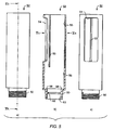
- the receiving part 42 has at the bottom an external thread 47 for screwing on the injection needle 38, and above an internal thread 48, which is for connection to the external thread 50 of an in Fig. 1 and 2 upper, distal housing part 52, which is in Fig. 5 is shown. It has a window 54 which serves to read the set injection dose, and has a cylindrical inner recess 56 which is in Fig. 5b) below via a shoulder 58, which serves as an axial bearing in an injection, merges into a recess 60 of smaller diameter, in which a shoulder 62 is located, which for the axial locking of the dosing (scale) 66 ( 6 and 7 ) in the housing part 52 serves.
- the shoulder 58 could be used as a thrust bearing, for example.
- a corresponding rolling bearing can be used.
- the metering 66 has a plurality of functions and therefore could also be referred to as dosing sleeve 66.
- the metering member (graduated tube, metering sleeve) 66 is provided on its cylindrical outer side 68 with numbers 70 for the display of the set injection dose and can therefore also be referred to as a scale tube. Also located on this outer side 68 is an external thread 72, the function of which will be explained below.
- the metering (scale) 66 goes on its proximal side via a shoulder 74, the bottom 76 as a counterpart to the thrust bearing 58 of the Fig. 5b) serves, in a cylindrical portion 78 of smaller diameter, in which in the mounted state of the radial projection 62 (FIG. Fig. 5b) of the housing 52 ( Fig. 5b) engages as the z. B. the Fig. 2 and 11 demonstrate.
- the portion 78 is bounded below by a radially projecting collar 80, which is followed by a downwardly section 82 with a slightly smaller outer diameter.
- the inside of the portion 78 is provided with an axial internal toothing 84, which serves for coupling with a complementary external axial toothing 86, which is located on a nut 88 which in the 8 to 11 is shown.
- This nut 88 has a rectangular internal thread 90 which is in engagement with the external thread 92 of a piston rod 94 whose shape is best from the Fig. 11 to 14 comes out. It serves according to Fig. 2 to do so, in one injection, the rubber piston 36 in the proximal To shift direction, so in Fig. 2 down to inject injection fluid 32 through the needle 38 into a patient. For this purpose, their external thread 92 is in engagement with a in FIGS.
- the piston rod 94 has at its distal part 98, the in Fig. 13 is shown above, a cross section ( Fig. 12 ), which deviates from the circular shape, and this part is in positive engagement with a complementary recess 99 (FIG. Fig. 18 ) of the rotary knob 40 ( Fig. 2 ), so that blocking the knob 40 against rotation also causes the piston rod 94 to lock against rotation, but allows axial displacement between the knob 40 and the piston rod 94. This will be described in detail below.
- the nut 88 has upstanding barbs 100, which engage with corresponding barbs 102 at the lower end of the metering 66.
- a pressure spring 104 is located between the section with the axial external toothing 86 and the section 82. This is compressed when, after the insertion of a new carpule 34, the internal thread 48 (FIG. Fig. 4 ) on the external thread 50 ( Fig. 5 ), whereby the axial outer toothing 86 (FIG. Fig. 8 ) of the nut 88 with the axial internal toothing 84 of the dosing (scale tube) 66 rotatably coupled, see. Fig. 11 ,
- the spring 104 When changing a carpule 34, the spring 104 ( Fig. 11 ) the axial gears 84, 86 apart, so that the nut 88 can rotate freely. This allows the physician or patient to rotate the nut 88 by hand so that the piston rod 94 is displaced all the way against the nut 88 in the distal direction and space for the insertion of a new carpule 34 is created.
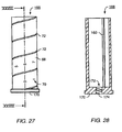
- FIGS. 27 and 28 demonstrate a simplified solution for this case, in which in a metering (scale) 166 also a thread 174 is provided, which cooperates with the external thread (92) of the piston rod 94.
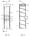
- a sleeve-shaped member for engagement in the external thread 72 of the metering (scale) 66 is a sleeve-shaped member in the form of an injection sleeve 116 is provided, which in the 15 to 17 is shown.
- Fig. 2 it is arranged between the metering member (graduated tube) 66 and the housing 52 and has an internal thread 118 (FIG. Fig. 17 ), which engages with the external thread 72 of the metering (scale) 66 ( Fig. 6 ) or 166 ( Fig.
- the axial movement of the injection sleeve 116 at the dose setting and at an injection also has an axial displacement of the window 130 (FIG. 15 to 17 ) result, which is provided in the shell portion 132 of the injection sleeve 116 and which is bounded above by a thickened shell portion 134 and down through a thickened shell portion 136.
- These thickened shell parts 134, 136 are in the window 54 ( Fig. 1 . 2 and 5 ) of the upper housing part 52.
- This dose indication thus decreases during an injection and thereby indicates to the patient how much he still has to inject.
- the patient has a constant control over the course of the injection and therefore knows exactly when the injection is completed when the display "0" appears in the viewing window and he can thus extract the injection needle from its fatty tissue without loss of injection liquid ,
- an external toothing 146 is provided on the tube 41, which is connected to the rotary knob 40, which - as well as the external toothing 125th Part of clutches K1 and K2 ( Fig. 25, 26th ), which is actuated by an axial displacement of the tube 41 (by means of the knob 40 and the compression spring 167 associated therewith).
- the outer toothing 146 is closed at the bottom by a plate-like flange 147 and works together with a complementary to their internal teeth 148 of a driver 150 which in the Fig. 21 to 24 is shown.
- the driver 150 has approximately the shape of a cylindrical tube 154, which is closed at the top by a kind of flange 156 which projects radially beyond the tube 154 with an edge 158.
- the axial internal toothing 148 is located in the center of the flange 156.
- the tube 154 is provided with a guide groove 157 provided with a corresponding projection 160 (FIG. Fig. 7 ) on the inside of the metering member (scale tube) 66 and 166 ( Fig. 28 ) cooperates so that rotation of the driver 150 (for dose setting) causes a corresponding rotation of the metering member (scale tube) 66.
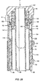
- the compression spring 167 acts on the knob 40 and the pipe connected to it 41 in the upward direction, cf. Fig. 25 in that the upper coupling K1 (11) formed by the outer axial toothing 125 (of the rotary knob 40) and the inner axial toothing 122 (of the injection sleeve 116) Fig. 25, 26th ) is opened, because the external axial teeth 125 does not engage in the axial internal teeth 122 of the injection sleeve 116.
- This makes it possible to set a desired injection dose because in this position the lower coupling K2 (FIG. Fig. 25 ) is closed because the axial external toothing 146 ( Fig. 19 .
- the knob 40 when the knob 40 is rotated in this position, it rotates over the tube 41 and the external axial toothing 146 (FIG. Fig. 20 ) and the internal toothing 148 (FIG. Fig. 21 ) the driver 150, and this rotates about its groove 158 the scale tube 166.
- the injection sleeve 116 in the distal direction ie axially upwards, moved, and with it the window 130.
- the nut 88th twisted, but this has no effect on the position of the rubber piston 36, because together with the nut 88 and the piston rod 94 rotates so that the latter can not change their axial position.
- Fig. 26 shows the situation with an injection.
- the patient first pricks the needle 38 (FIG. Fig. 1 . 2 . 30 ) and then presses with a force F ( Fig. 26 It thereby opens the clutch K2 and closes the clutch K1, whereby it causes the tube 41 and the piston rod 94 (see FIG. Fig. 2 ) rotatably connects with the injection sleeve 116 and consequently with the housing 52, so that now the piston rod 94 can not rotate relative to the housing 52.
- the injection sleeve 116 Due to the force F (of the patient), the injection sleeve 116 is moved around the previously ( Fig. 25 ) preselected way down to the zero position and rotated by the threaded connection between the internal thread 118 of the injection sleeve 116 and the external thread 72 of the metering (scale) 66 of this scale tube and with it the nut 88 ( Fig. 8 to 10 ), so that the piston rod 94, which can not rotate, is moved in the proximal direction by the rotation of the nut 88 and the internal thread 90 provided in it, and causes an injection because it displaces the rubber piston 36 in the proximal direction by the set dose ,
- a mechanical translation can be provided, d. H. that a displacement of the injection sleeve 116 by a set path D causes a movement of the piston rod 94 by a distance D / f, where f depending on the design of the thread pitches can assume values between about 0.5 and 2. This allows for a smaller dose of doses a more accurate indication of the dose and has proven to be particularly beneficial in low-vision patients.
- FIGS. 27 and 28 show a scale tube 166 for a so-called, here only in part illustrated disposable injection device, that is for an injection device, in which the (in FIGS. 27 and 28 not shown) carpule 34 can not be replaced. Therefore, the injection device must be disposed of when the carpule is empty.
- the structure of the metering (scale) 166 largely corresponds to the metering (scale) 66 after 6 and 7 That is, on its outer side 68 and the scale tube 166 has an external thread 72 and scale values 70, and inside it has a projection 160 for the longitudinal guide in a longitudinal groove 157 of the driver 150, see. the Fig. 21 to 24 , Also has the metering (scale) 166 of the FIGS.
- Fig. 29 shows the process of dose adjustment, wherein the carpule 34 and the carpule container 42 are not shown to make the representation more vivid.
- the rubber piston 36 of the carpule 34 is indicated by dash-dotted lines.
- the dose is adjusted here by an axial displacement of the injection sleeve 116 in the distal direction, while the position of the plate 96 relative to the rubber piston 36 does not change when setting the dose.
- the piston rod 94 rotates relative to the rubber piston 36
- the proximal end 95 of the piston rod 94 tapers downwards, so that there, the friction between the end 95 and the rubber piston 36 is low.
- Fig. 31 shows a longitudinal section analog Fig. 2 in which four different horizontal sections CC, DD. EE and FF are registered.
- the reference numerals are the same as in the previous figures, and it is not a disposable syringe.
- Fig. 32 shows outside the carpule container 42, therein the barbs 100, then the barbs 82 and the spring 104, as well as the external teeth 86 of the part 88, as well as completely inside the piston rod 94 with its external thread 92nd
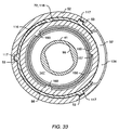
- Fig. 33 shows that the tube 41 has an axial recess 99 in which the part 98 (FIG. FIGS. 12 and 13 ) of the piston rod 94 is non-rotatably, but longitudinally displaceable, guided. This makes it possible, by pressing the knob 40 (see. Fig. 26 ) to connect the piston rod 94 with the housing 52 so that the tube 41 can not rotate relative to the housing 52.
- the metering (scale) 66 has three Longitudinal ribs 160, which are guided in corresponding longitudinal grooves 157 of the driver 150.
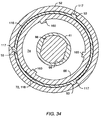
- Fig. 34 shows outside the housing 52 with its three longitudinal grooves 53, in which the injection sleeve 116 is guided with its three longitudinal ribs 117.
- the injection sleeve 116 is connected via the thread 72, 118 with the metering (scale) 66, which in turn is provided on its inside with three longitudinal ribs 160.
- Fig. 35 shows the section FF the Fig. 31 , Outside is the housing 52, in which according to Fig. 5 the longitudinal grooves 53 are provided, in which three corresponding ribs 117 of the injection sleeve 116 engage.
- the inside of the injection sleeve 116 is connected via the thread 72, 118 with the outside of the metering (scale) tube 66.
- the inside of the metering (scale) 66 has three longitudinal ribs 160 which are guided in longitudinal grooves 154 of the driver 150. This has an internal toothing 148 which is in engagement with the external toothing 146 of the tube 41.
- Fig. 36 shows an exploded view of the injection device 30, which is for ease of understanding.
- the knob 40 with its teeth 125, according to Fig. 20 is firmly connected to the tube 41.
- the latter is provided with the outer toothing 146, which as part of the coupling K2 (FIG. Fig. 25 and 26 ) serves.
- the driver tube 150 ( Fig. 21 to 24 ), which has three longitudinal grooves 157 on its outside 154, cf. Fig. 35 of which in Fig. 36 only one is visible.
- the driving tube 150 with the metering (scale) 66 rotatably, but axially displaceable, coupled.
- the metering (scale) 66 is provided on its inside with corresponding longitudinal projections 160 for engagement in the longitudinal grooves 157, see. the Fig. 33 and 35 ,
- the piston rod 94 is axially slidably guided, but non-rotatably connected by a non-circular part 98 with the tube 41, so that rotation of the knob 40 also causes rotation of the piston rod 94, while a locking of the knob 40 and the piston rod 94 against rotation locked, but their axial displacement in the tube 40 is not hindered.
- the housing part 52 On the metering (scale) 66, which is provided with an external thread 72, that is Internal thread 118 (see the Fig. 15 and 17 ) of the injection sleeve 116 ( Fig. 35 ), which is provided on its outside with three longitudinal projections 117, with which the injection sleeve 116 is guided in the housing part 52 in the longitudinal direction.
- the housing part 52 has three longitudinal grooves 53 in the Fig. 5 . 33 and 35 are shown.
- the housing part 52 is provided at its proximal end with the external thread 50, which serves for connection to the housing part 42, which in 3 and 4 represented, but in Fig. 36 has been omitted for the sake of clarity.
- the metering (scale) 66 is locked in the housing part 52 in the longitudinal direction, see. Fig. 11 .
- the spring 104 cooperates with the nut 88, see. Fig. 11 .
- At the bottom of Fig. 36 is the Anpressophil 96 shown, which is mounted after assembly at the lower end 95 of the piston rod 94, see. Fig. 30 ,
- injection device 30 consists of only a few simple parts which are very easy to assemble and which are well suited for automated production.
- many modifications and modifications are possible within the scope of the present invention.
- z. B. the parts of the injection device made of plastic injection molding, but highly stressed parts can also be made of metal or a special plastic, such as a plastic with glass fiber reinforcement. Such and other modifications are within the scope of the skilled art.
- the metering element 66, 88; 166 and an external thread 92 having first member 94 is not rotatable relative to each other.
- the metering element 66, 88; 166 and the external thread 92 having first member 94 together rotatable relative to the housing 52.
- a coupling arrangement K2 is to transmit a dose setting movement to the metering member 66 for preselecting a desired injection dose.
- the metering member in the manner of a sleeve 66, 88; 166 trained.
- the injection device has a coupling device K2, 146, 148, 150, which is disengaged during an injection process.
- the first provided with an external thread 92 organ as a plunger 94 is formed, which is provided with an external thread 92.
- the proximal end 95 of the first member 94 is rotatably mounted in a pressing member 96 which is formed for expressing injection liquid 32 from a container 34 for such a liquid 32, said proximal end 95 of the first member 94 is recessed in the pressing member 96 ( Fig. 30 ).
Landscapes
- Health & Medical Sciences (AREA)
- Public Health (AREA)
- Veterinary Medicine (AREA)
- Anesthesiology (AREA)
- Vascular Medicine (AREA)
- Heart & Thoracic Surgery (AREA)
- Hematology (AREA)
- Life Sciences & Earth Sciences (AREA)
- Animal Behavior & Ethology (AREA)
- Engineering & Computer Science (AREA)
- General Health & Medical Sciences (AREA)
- Biomedical Technology (AREA)
- Infusion, Injection, And Reservoir Apparatuses (AREA)
- Injection Moulding Of Plastics Or The Like (AREA)
- Chemical Or Physical Treatment Of Fibers (AREA)
- Polarising Elements (AREA)
- Eye Examination Apparatus (AREA)
- Noodles (AREA)
- Diaphragms For Electromechanical Transducers (AREA)
- Measuring And Recording Apparatus For Diagnosis (AREA)
Claims (8)
- Dispositif d'injection, qui présente :un boîtier (52) ;un récipient (34) pour recevoir du liquide à injecter (32), le récipient (34) pouvant être relié au boîtier (52) ;un organe de dosage (66, 88 ; 166), qui est conçu rotatif par rapport au boîtier (42, 52),mais sans possibilité de translation axiale ;un filetage extérieur (72) associé à l'organe de dosage (66, 88 ; 166) ;un organe en forme de manchon (116), qui est conçu à déplacement axial dans le boîtier (52), mais sans possibilité de rotation par rapport au boîtier (52), et qui présente un filetage intérieur (118) qui est en prise avec le filetage extérieur (72) de l'organe de dosage (66, 88 ; 166) ;afin, par la rotation de l'organe de dosage (66, 88 ; 166) par rapport au boîtier (52), de permettre une translation axiale de l'organe en forme de manchon (116) dans le boîtier (52) et ainsi le réglage d'une dose d'injection ;et un dispositif de couplage (K1), qui est en prise avec l'organe en forme de manchon (116) pendant le processus d'injection et qui peut être désaccouplé de l'organe en forme de manchon (116) afin de présélectionner une dose d'injection souhaitée.
- Dispositif d'injection selon la revendication 1, dans lequel des valeurs d'affichage (figure 6 : 70) pour la dose d'injection sont prévues sur l'organe de dosage (66, 88 ; 166).
- Dispositif d'injection selon la revendication 2, dans lequel les valeurs d'affichage (70) sont disposées sensiblement en spirale sur l'organe de dosage (66 ; 166).
- Dispositif d'injection selon l'une des revendications précédentes, qui présente :un premier regard (54) prévu dans le boîtier (52) du dispositif d'injection ;et un deuxième regard (130), qui est prévu dans l'organe en forme de manchon (116) etqui est à translation axiale par rapport au premier regard (54) ;afin de rendre visible, à travers le premier regard (54) et le deuxième regard (130), une valeur d'affichage (70) pour la dose d'injection sur le côté extérieur (68) de l'organe de dosage (66 ; 166).
- Dispositif d'injection selon la revendication 4, dans lequel le deuxième regard (130) prévu dans l'organe en forme de manchon (116) est dimensionné de telle sorte qu'il correspond sensiblement à la surface occupée par une valeur d'affichage (70) pour la dose d'injection et qu'il recouvre par sa périphérie (134, 136) les valeurs d'affichage voisines.
- Dispositif d'injection selon la revendication 4 ou 5, dans lequel le premier regard (54) prévu dans le boîtier (52) présente la forme d'un évidement oblong dont l'axe longitudinal s'étend au moins quasiment dans la direction longitudinale du boîtier (52).
- Dispositif d'injection selon l'une des revendications 4 à 6, dans lequel l'évidement oblong du premier regard (54) prévu dans le boîtier (52) est dimensionné de telle sorte qu'on peut voir à travers les regards concernés (54, 130) la valeur de dosage minimale dans la position finale proximale du deuxième regard (130) et la valeur de dosage maximale dans la position finale distale du deuxième regard (130).
- Dispositif d'injection selon l'une des revendications précédentes, dans lequel l'organe de dosage est réalisé à la manière d'un manchon (66 ; 166).
Priority Applications (1)
| Application Number | Priority Date | Filing Date | Title |
|---|---|---|---|
| PL10000953T PL2174682T3 (pl) | 2007-05-25 | 2007-11-05 | Urządzenie do iniekcji |
Applications Claiming Priority (2)
| Application Number | Priority Date | Filing Date | Title |
|---|---|---|---|
| DE102007026083A DE102007026083A1 (de) | 2007-05-25 | 2007-05-25 | Injektionsgerät |
| EP07819575.7A EP2150299B2 (fr) | 2007-05-25 | 2007-11-05 | Dispositif d'injection |
Related Parent Applications (2)
| Application Number | Title | Priority Date | Filing Date |
|---|---|---|---|
| EP07819575.7A Division-Into EP2150299B2 (fr) | 2007-05-25 | 2007-11-05 | Dispositif d'injection |
| EP07819575.7 Division | 2007-11-05 |
Publications (2)
| Publication Number | Publication Date |
|---|---|
| EP2174682A1 EP2174682A1 (fr) | 2010-04-14 |
| EP2174682B1 true EP2174682B1 (fr) | 2012-11-14 |
Family
ID=39047584
Family Applications (2)
| Application Number | Title | Priority Date | Filing Date |
|---|---|---|---|
| EP10000953A Active EP2174682B1 (fr) | 2007-05-25 | 2007-11-05 | Dispositif d'injection |
| EP07819575.7A Active EP2150299B2 (fr) | 2007-05-25 | 2007-11-05 | Dispositif d'injection |
Family Applications After (1)
| Application Number | Title | Priority Date | Filing Date |
|---|---|---|---|
| EP07819575.7A Active EP2150299B2 (fr) | 2007-05-25 | 2007-11-05 | Dispositif d'injection |
Country Status (10)
| Country | Link |
|---|---|
| US (1) | US8512296B2 (fr) |
| EP (2) | EP2174682B1 (fr) |
| JP (2) | JP5156092B2 (fr) |
| AT (1) | ATE530215T1 (fr) |
| CA (1) | CA2687041C (fr) |
| DE (1) | DE102007026083A1 (fr) |
| DK (2) | DK2150299T4 (fr) |
| ES (2) | ES2399500T3 (fr) |
| PL (2) | PL2174682T3 (fr) |
| WO (1) | WO2008145171A1 (fr) |
Cited By (15)
| Publication number | Priority date | Publication date | Assignee | Title |
|---|---|---|---|---|
| US8945063B2 (en) | 2009-03-20 | 2015-02-03 | Antares Pharma, Inc. | Hazardous agent injection system |
| US9144648B2 (en) | 2006-05-03 | 2015-09-29 | Antares Pharma, Inc. | Injector with adjustable dosing |
| US9180259B2 (en) | 2005-01-24 | 2015-11-10 | Antares Pharma, Inc. | Prefilled syringe jet injector |
| US9220660B2 (en) | 2011-07-15 | 2015-12-29 | Antares Pharma, Inc. | Liquid-transfer adapter beveled spike |
| US9333309B2 (en) | 2002-02-11 | 2016-05-10 | Antares Pharma, Inc. | Intradermal injector |
| US9364610B2 (en) | 2012-05-07 | 2016-06-14 | Antares Pharma, Inc. | Injection device with cammed ram assembly |
| US9393367B2 (en) | 2013-03-12 | 2016-07-19 | Antares Pharma, Inc. | Prefilled syringes and kits thereof |
| US9446195B2 (en) | 2011-07-15 | 2016-09-20 | Antares Pharma, Inc. | Injection device with cammed ram assembly |
| US9486583B2 (en) | 2012-03-06 | 2016-11-08 | Antares Pharma, Inc. | Prefilled syringe with breakaway force feature |
| US9561333B2 (en) | 2008-08-05 | 2017-02-07 | Antares Pharma, Inc. | Multiple dosage injector |
| US9744302B2 (en) | 2013-02-11 | 2017-08-29 | Antares Pharma, Inc. | Needle assisted jet injection device having reduced trigger force |
| US9808582B2 (en) | 2006-05-03 | 2017-11-07 | Antares Pharma, Inc. | Two-stage reconstituting injector |
| US9867949B2 (en) | 2008-03-10 | 2018-01-16 | Antares Pharma, Inc. | Injector safety device |
| US9950125B2 (en) | 2012-04-06 | 2018-04-24 | Antares Pharma, Inc. | Needle assisted jet injection administration of testosterone compositions |
| US10610649B2 (en) | 2013-03-11 | 2020-04-07 | Antares Pharma, Inc. | Multiple dosage injector with rack and pinion dosage system |
Families Citing this family (118)
| Publication number | Priority date | Publication date | Assignee | Title |
|---|---|---|---|---|
| US7381184B2 (en) | 2002-11-05 | 2008-06-03 | Abbott Diabetes Care Inc. | Sensor inserter assembly |
| USD914881S1 (en) | 2003-11-05 | 2021-03-30 | Abbott Diabetes Care Inc. | Analyte sensor electronic mount |
| US7883464B2 (en) | 2005-09-30 | 2011-02-08 | Abbott Diabetes Care Inc. | Integrated transmitter unit and sensor introducer mechanism and methods of use |
| US9572534B2 (en) | 2010-06-29 | 2017-02-21 | Abbott Diabetes Care Inc. | Devices, systems and methods for on-skin or on-body mounting of medical devices |
| US8029441B2 (en) | 2006-02-28 | 2011-10-04 | Abbott Diabetes Care Inc. | Analyte sensor transmitter unit configuration for a data monitoring and management system |
| US9788771B2 (en) | 2006-10-23 | 2017-10-17 | Abbott Diabetes Care Inc. | Variable speed sensor insertion devices and methods of use |
| US9398882B2 (en) | 2005-09-30 | 2016-07-26 | Abbott Diabetes Care Inc. | Method and apparatus for providing analyte sensor and data processing device |
| US10226207B2 (en) | 2004-12-29 | 2019-03-12 | Abbott Diabetes Care Inc. | Sensor inserter having introducer |
| US8512243B2 (en) | 2005-09-30 | 2013-08-20 | Abbott Diabetes Care Inc. | Integrated introducer and transmitter assembly and methods of use |
| US8333714B2 (en) | 2006-09-10 | 2012-12-18 | Abbott Diabetes Care Inc. | Method and system for providing an integrated analyte sensor insertion device and data processing unit |
| US9259175B2 (en) | 2006-10-23 | 2016-02-16 | Abbott Diabetes Care, Inc. | Flexible patch for fluid delivery and monitoring body analytes |
| US7697967B2 (en) * | 2005-12-28 | 2010-04-13 | Abbott Diabetes Care Inc. | Method and apparatus for providing analyte sensor insertion |
| US20090105569A1 (en) | 2006-04-28 | 2009-04-23 | Abbott Diabetes Care, Inc. | Introducer Assembly and Methods of Use |
| US9521968B2 (en) | 2005-09-30 | 2016-12-20 | Abbott Diabetes Care Inc. | Analyte sensor retention mechanism and methods of use |
| US11298058B2 (en) | 2005-12-28 | 2022-04-12 | Abbott Diabetes Care Inc. | Method and apparatus for providing analyte sensor insertion |
| DE202008011175U1 (de) * | 2008-08-18 | 2010-01-07 | Haselmeier Gmbh | Injektionsgerät |
| DK2355870T3 (en) | 2008-12-12 | 2016-06-06 | Shl Group Ab | Drug delivery devices |
| US9402544B2 (en) | 2009-02-03 | 2016-08-02 | Abbott Diabetes Care Inc. | Analyte sensor and apparatus for insertion of the sensor |
| US8672896B2 (en) | 2009-06-01 | 2014-03-18 | Sanofi-Aventis Deutschland Gmbh | Inner housing for a drug delivery device |
| US9345840B2 (en) | 2009-06-01 | 2016-05-24 | Sanofi-Aventis Deutschland Gmbh | Drug delivery dose setting mechanism with variable maximum dose |
| US9238106B2 (en) | 2009-06-01 | 2016-01-19 | Sanofi-Aventis Deutschland Gmbh | Dose setting mechanism for priming a drug delivery device |
| US9463283B2 (en) | 2009-06-01 | 2016-10-11 | Sanofi-Aventis Deutschland Gmbh | Dosing mechanism for a drug deliver device |
| US9125994B2 (en) | 2009-06-01 | 2015-09-08 | Sanofi—Aventis Deutschland GmbH | Drug delivery device with dose dial sleeve rotational stop |
| US9108007B2 (en) * | 2009-06-01 | 2015-08-18 | Sanofi-Aventis Deutschland Gmbh | Spindle and bearing combination and drug delivery device |
| US9457150B2 (en) | 2009-06-01 | 2016-10-04 | Sanofi-Aventis Deutschland Gmbh | Biasing mechanism for a drug delivery device |
| US8728043B2 (en) | 2009-06-01 | 2014-05-20 | Sanofi-Aventis Deutschland Gmbh | Drive mechanism for a drug delivery device |
| US9623187B2 (en) | 2009-06-01 | 2017-04-18 | Sanofi-Aventis Deutschland Gmbh | Resettable drug delivery device |
| US8257319B2 (en) | 2009-06-01 | 2012-09-04 | Sanofi-Aventis Deutschland Gmbh | Drug delivery device inner housing having helical spline |
| US8974423B2 (en) | 2009-06-01 | 2015-03-10 | Sanofi-Aventis Deutschland Gmbh | Resettable drug delivery device |
| US9950116B2 (en) | 2009-06-01 | 2018-04-24 | Sanofi-Aventis Deutschland Gmbh | Dose setting mechanism for priming a drug delivery device |
| US9199040B2 (en) | 2009-06-01 | 2015-12-01 | Sanofi-Aventis Deutschland Gmbh | Drug delivery device last dose lock-out mechanism |
| US10034982B2 (en) | 2009-06-01 | 2018-07-31 | Sanofi-Aventis Deutschland Gmbh | Spindle for a drug delivery device |
| US8585656B2 (en) | 2009-06-01 | 2013-11-19 | Sanofi-Aventis Deutschland Gmbh | Dose setting mechanism for priming a drug delivery device |
| US9089646B2 (en) | 2009-08-27 | 2015-07-28 | Sanofi-Aventis Deutshcland GmbH | Housing component for a drug delivery device |
| WO2011025549A1 (fr) | 2009-08-31 | 2011-03-03 | Abbott Diabetes Care Inc. | Dispositifs et procédés médicaux |
| JP5703299B2 (ja) * | 2009-09-07 | 2015-04-15 | サノフィ−アベンティス・ドイチュラント・ゲゼルシャフト・ミット・ベシュレンクテル・ハフツング | 薬物送達デバイスのための駆動機構 |
| DE102009048497A1 (de) * | 2009-09-26 | 2011-03-31 | Haselmeier Gmbh | Injektionsgerät |
| US8939945B2 (en) | 2009-09-30 | 2015-01-27 | Sanofi-Aventis Deutschland Gmbh | Drive mechanism for a drug delivery device |
| EP2311513A1 (fr) * | 2009-10-16 | 2011-04-20 | Sanofi-Aventis Deutschland GmbH | Ensemble support de cartouche pour dispositif d'administration de médicaments |
| GB0918145D0 (en) | 2009-10-16 | 2009-12-02 | Owen Mumford Ltd | Injector apparatus |
| CA2766685A1 (fr) | 2010-03-24 | 2011-12-29 | Abbott Diabetes Care Inc. | Appareils d'insertion de dispositifs medicaux et procedes d'insertion et d'utilisation de dispositifs medicaux |
| US9623185B2 (en) | 2010-06-11 | 2017-04-18 | Sanofi-Aventis Deutschland Gmbh | Assembly for a drug delivery device and drug delivery device |
| US11064921B2 (en) | 2010-06-29 | 2021-07-20 | Abbott Diabetes Care Inc. | Devices, systems and methods for on-skin or on-body mounting of medical devices |
| US9248239B2 (en) | 2010-11-29 | 2016-02-02 | Sanofi-Aventis Deutschland Gmbh | Drug delivery device having linked dose dial components |
| JP5984831B2 (ja) * | 2010-11-29 | 2016-09-06 | サノフィ−アベンティス・ドイチュラント・ゲゼルシャフト・ミット・ベシュレンクテル・ハフツング | 連結用量ダイヤル部材を有する薬物送達デバイス |
| AU2012253905B2 (en) | 2011-05-06 | 2016-04-14 | Merit Medical Systems, Inc. | Mechanically assisted inflation device handle and method of use |
| ES2871477T3 (es) * | 2011-05-19 | 2021-10-29 | Becton Dickinson Co | Dispositivo de inyección con varias ventanas de ajuste de dosis |
| WO2013053781A1 (fr) * | 2011-10-14 | 2013-04-18 | Sanofi-Aventis Deutschland Gmbh | Assemblage pour un dispositif d'administration de médicament |
| WO2013090215A2 (fr) | 2011-12-11 | 2013-06-20 | Abbot Diabetes Care Inc. | Dispositifs détecteurs d'analytes, connexions, et procédés |
| EP2806924A1 (fr) * | 2012-01-27 | 2014-12-03 | Michael A. Creaturo | Kit combinant seringue de sécurité et dose de sécurité |
| EP2806925B1 (fr) | 2012-01-27 | 2016-01-13 | Novo Nordisk A/S | Dispositif d'injection avec une échelle mobile |
| CH703993A2 (de) | 2012-02-09 | 2012-03-15 | Tecpharma Licensing Ag | Injektionsgerät zur Verabreichung oder Förderung von fluidem Produkt. |
| DE202012001411U1 (de) * | 2012-02-10 | 2013-05-13 | Haselmeier Gmbh | Injektionsgerät |
| WO2013144020A1 (fr) * | 2012-03-30 | 2013-10-03 | Tecpharma Licensing Ag | Dispositif d'injection comprenant un élément indicateur de dose qui peut se déplacer par rapport à un boîtier |
| EP2644218B2 (fr) | 2012-03-30 | 2022-11-02 | Tecpharma Licensing AG | Dispositif d'injection avec affichage de dose et entraînement par ressort |
| EP2644217A1 (fr) | 2012-03-30 | 2013-10-02 | TecPharma Licensing AG | Dispositif d'injection avec affichage de dose et entraînement par ressort |
| CN104321095B (zh) * | 2012-04-13 | 2018-07-24 | 贝克顿·迪金森公司 | 具有用于指示部件适当连接的指示器的自注射装置 |
| JP6011913B2 (ja) * | 2012-06-29 | 2016-10-25 | 株式会社吉野工業所 | 可変計量容器 |
| WO2014055456A1 (fr) * | 2012-10-07 | 2014-04-10 | Abbott Diabetes Care Inc. | Indicateurs d'introduction de dispositif médical |
| WO2014166915A1 (fr) * | 2013-04-10 | 2014-10-16 | Sanofi | Ensemble d'affichage pour dispositif d'administration de médicament |
| TW201509471A (zh) * | 2013-04-10 | 2015-03-16 | Sanofi Sa | 注射裝置(十一) |
| MX2015014291A (es) | 2013-04-10 | 2016-01-20 | Sanofi Sa | Dispositivo de inyeccion. |
| JP6515085B2 (ja) | 2013-04-10 | 2019-05-15 | サノフイSanofi | 注射デバイス |
| CN105073167A (zh) | 2013-04-10 | 2015-11-18 | 赛诺菲 | 注射装置 |
| MX2015014297A (es) | 2013-04-10 | 2015-12-08 | Sanofi Sa | Dispositivo de inyeccion. |
| RU2015147868A (ru) * | 2013-04-10 | 2017-05-22 | Санофи | Инъекционное устройство |
| US10688248B2 (en) | 2013-04-10 | 2020-06-23 | Sanofi | Injection device |
| WO2014166912A1 (fr) * | 2013-04-10 | 2014-10-16 | Sanofi | Dispositif d'injection |
| EP2801335B1 (fr) * | 2013-05-07 | 2018-03-14 | Ivoclar Vivadent AG | Seringue |
| DK2996743T3 (en) * | 2013-05-16 | 2019-04-01 | Sanofi Aventis Deutschland | DEVICE FOR A PHARMACEUTICAL ADMINISTRATION DEVICE AND PHARMACEUTICAL ADMINISTRATION DEVICE |
| TW201511785A (zh) * | 2013-07-17 | 2015-04-01 | Sanofi Sa | 顯示器總成及施配裝置 |
| ES2909901T3 (es) | 2013-08-02 | 2022-05-10 | Becton Dickinson Co | Pluma de inyección |
| US20150051543A1 (en) * | 2013-08-16 | 2015-02-19 | Merit Medical Systems, Inc. | High-pressure inflation devices and methods of use |
| HK1222143A1 (zh) * | 2013-09-03 | 2017-06-23 | Sanofi | 用於药物传送装置的机构和包括该机构的药物传送装置 |
| CN105792867A (zh) * | 2013-09-03 | 2016-07-20 | 赛诺菲 | 用于药物传送装置的机构和包括该机构的药物传送装置 |
| AR097610A1 (es) * | 2013-09-03 | 2016-04-06 | Sanofi Sa | Mecanismo para un dispositivo de administración de medicamento, y dispositivo de administración de medicamento que comprende el mecanismo |
| EP2881131B1 (fr) * | 2013-12-05 | 2019-04-24 | TecPharma Licensing AG | Dispositif d'entraînement et de dosage pour un dispositif d'injection doté d'un ressort d'entraînement précontraint |
| DE202014001136U1 (de) * | 2014-02-05 | 2015-05-06 | Haselmeier Gmbh | Injektionsgerät |
| DE202014001135U1 (de) * | 2014-02-05 | 2015-05-06 | Haselmeier Gmbh | Injektionsgerät |
| DK3155378T3 (da) | 2014-06-10 | 2019-08-19 | Sanofi Aventis Deutschland | Sensoranordning, der kan fastgøres aftageligt til en lægemiddeladministrationsanordning |
| CN105233373B (zh) * | 2014-06-26 | 2018-05-18 | 群康生技股份有限公司 | 注射器的循环开关机构 |
| CN105311714B (zh) * | 2014-06-26 | 2018-08-17 | 群康生技股份有限公司 | 注射器的螺旋导引机构 |
| EP3180054B1 (fr) | 2014-08-15 | 2019-12-18 | Eli Lilly and Company | Dispositif médicament d'injection automatique à indication visible de progrès d'injection |
| TW201625324A (zh) * | 2014-10-09 | 2016-07-16 | 賽諾菲公司 | 殼體及具有該殼體的藥物輸送裝置 |
| TW201632214A (zh) | 2014-10-09 | 2016-09-16 | 賽諾菲公司 | 組裝驅動彈簧之方法及具有彈簧之藥物輸送裝置 |
| AR102190A1 (es) * | 2014-10-09 | 2017-02-08 | Sanofi Sa | Dispositivo de administración de fármacos |
| JP2017530822A (ja) * | 2014-10-16 | 2017-10-19 | サノフィ−アベンティス・ドイチュラント・ゲゼルシャフト・ミット・ベシュレンクテル・ハフツング | 窓要素、および薬物送達デバイス |
| US10576214B2 (en) | 2014-11-24 | 2020-03-03 | Sanofi | Display and drug delivery device |
| US9474864B2 (en) * | 2014-12-15 | 2016-10-25 | Brell Medical Innovations, LLC | Safety syringe and methods for administration of a medicament dose by subject weight |
| CN106139322A (zh) * | 2015-04-01 | 2016-11-23 | 群康生技股份有限公司 | 注射笔的锁定构造 |
| US10213139B2 (en) | 2015-05-14 | 2019-02-26 | Abbott Diabetes Care Inc. | Systems, devices, and methods for assembling an applicator and sensor control device |
| AU2016260547B2 (en) | 2015-05-14 | 2020-09-03 | Abbott Diabetes Care Inc. | Compact medical device inserters and related systems and methods |
| JP7005484B2 (ja) * | 2015-07-29 | 2022-01-21 | サノフィ-アベンティス・ドイチュラント・ゲゼルシャフト・ミット・ベシュレンクテル・ハフツング | 薬物送達デバイス用のセンサデバイス |
| DE202015006841U1 (de) * | 2015-09-30 | 2016-01-15 | Haselmeier Ag | Injektionsgerät |
| DE202015006845U1 (de) * | 2015-09-30 | 2016-01-15 | Haselmeier Ag | Injektionsgerät |
| EP3386569B1 (fr) | 2015-12-10 | 2025-08-13 | Sanofi-Aventis Deutschland GmbH | Dispositif d'administration de médicament avec dispositif de détection pouvant être fixé de manière amovible |
| TW201731543A (zh) | 2015-12-10 | 2017-09-16 | 賽諾菲阿凡提斯德意志有限公司 | 可移除地附接於藥物輸送裝置之感測裝置 |
| USD876622S1 (en) | 2016-09-19 | 2020-02-25 | Merit Medical Systems, Inc. | High pressure mechanically assisted device handle |
| CN115444410B (zh) | 2017-01-23 | 2025-08-15 | 雅培糖尿病护理公司 | 用于插入体内分析物传感器的施加器及组件 |
| WO2019162222A1 (fr) | 2018-02-26 | 2019-08-29 | Haselmeier Ag | Détermination de dosage à l'aide de la conductivité électrique dans un dispositif d'injection |
| WO2020035217A1 (fr) | 2018-08-16 | 2020-02-20 | Haselmeier Ag | Dispositifs médicaux adaptés aux microfils |
| WO2020131159A1 (fr) | 2018-12-21 | 2020-06-25 | Abbott Diabetes Care Inc. | Systèmes, dispositifs et procédés d'insertion de capteur d'analyte |
| USD1002852S1 (en) | 2019-06-06 | 2023-10-24 | Abbott Diabetes Care Inc. | Analyte sensor device |
| KR102235971B1 (ko) * | 2019-06-17 | 2021-04-05 | 노욱래 | 전후 이동이 가능한 플런저 및 이를 포함하는 약물 주입 장치 |
| EP3999150A1 (fr) | 2019-10-08 | 2022-05-25 | medmix Switzerland AG | Raccords à clavette pour dispositifs d'administration de médicaments |
| CN115175716A (zh) * | 2019-11-18 | 2022-10-11 | 迈德米斯瑞士股份公司 | 药物输送设备 |
| CN115942909A (zh) | 2020-08-31 | 2023-04-07 | 雅培糖尿病护理公司 | 用于分析物传感器插入的系统、装置和方法 |
| ES3000715T3 (en) | 2020-09-15 | 2025-03-03 | Abbott Diabetes Care Inc | Device for analyte monitoring |
| USD999913S1 (en) | 2020-12-21 | 2023-09-26 | Abbott Diabetes Care Inc | Analyte sensor inserter |
| KR102579563B1 (ko) * | 2021-03-24 | 2023-09-18 | 주식회사 바로메디 | 양방향 플런저가 포함된 약제 주입장치 및 이의 사용방법 |
| EP4070832A1 (fr) * | 2021-04-07 | 2022-10-12 | medmix Switzerland AG | Connecteurs clavetés |
| WO2022214624A1 (fr) * | 2021-04-07 | 2022-10-13 | Medmix Switzerland Ag | Dispositif d'administration de médicament comprenant un poids d'équilibrage |
| CN117425510A (zh) * | 2021-04-07 | 2024-01-19 | 迈德米斯瑞士股份公司 | 药物输送设备 |
| IT202100012020A1 (it) | 2021-05-11 | 2022-11-11 | Stevanato Group Spa | Dispositivo di iniezione di un farmaco |
| MY202051A (en) | 2021-07-16 | 2024-03-30 | Abbott Diabetes Care Inc | Systems, devices, and methods for analyte monitoring |
| IT202100032357A1 (it) | 2021-12-23 | 2023-06-23 | Stevanato Group Spa | Dispositivo di iniezione di un farmaco |
| USD1109322S1 (en) | 2023-10-02 | 2026-01-13 | Regeneron Pharmaceuticals, Inc. | Drug-delivery device |
| USD1108627S1 (en) | 2023-10-02 | 2026-01-06 | Regeneron Pharmaceuticals, Inc. | Drug-delivery device |
Family Cites Families (20)
| Publication number | Priority date | Publication date | Assignee | Title |
|---|---|---|---|---|
| AT74777B (de) | 1915-06-23 | 1918-10-10 | Reiniger Gebbert & Schall Ag | Schaltungsanordnung zum Schutz von Röntgenröhren vor schädlicher Aufladung. |
| DK166948B1 (da) * | 1988-02-10 | 1993-08-09 | Dcp Af 1988 As | Doseringsenhed til dosering af et antal afmaalte maengder af en vaeske, saasom insulin, fra en glastubule |
| US5674204A (en) | 1995-09-19 | 1997-10-07 | Becton Dickinson And Company | Medication delivery pen cap actuated dose delivery clutch |
| JP3739406B2 (ja) * | 1995-11-09 | 2006-01-25 | テクファーマ・ライセンシング・アクチェンゲゼルシャフト | 液体薬剤を収容する注射装置 |
| PT828527E (pt) * | 1996-04-02 | 2002-12-31 | Disetronic Licensing Ag | Dispositivo para injeccao |
| CZ297361B6 (cs) * | 1998-01-30 | 2006-11-15 | Novo Nordisk A/S | Injekcní stríkacka |
| US6221053B1 (en) * | 1998-02-20 | 2001-04-24 | Becton, Dickinson And Company | Multi-featured medication delivery pen |
| US6899699B2 (en) * | 2001-01-05 | 2005-05-31 | Novo Nordisk A/S | Automatic injection device with reset feature |
| DE10163328B4 (de) * | 2001-07-30 | 2005-08-11 | Tecpharma Licensing Ag | Verabreichungsgerät mit Verdrehsicherung |
| DE10163325B4 (de) * | 2001-07-30 | 2005-07-28 | Tecpharma Licensing Ag | Verriegelungssperre für eine Verbindung von Gehäuseabschnitten eines Verabreichungsgeräts |
| GB0304822D0 (en) * | 2003-03-03 | 2003-04-09 | Dca Internat Ltd | Improvements in and relating to a pen-type injector |
| TR201903984T4 (tr) * | 2003-08-12 | 2019-04-22 | Lilly Co Eli | Mekanik avantaja yönelik üçlü vida dişine sahip ilaç dağıtım aparatı. |
| DE10343548B4 (de) * | 2003-09-19 | 2008-03-27 | Tecpharma Licensing Ag | Vorrichtung für eine dosierte Abgabe eines injizierbaren Produkts |
| DE20317377U1 (de) * | 2003-11-03 | 2005-03-17 | B D Medico S A R L | Injektionsgerät |
| MX2007003682A (es) * | 2004-10-04 | 2007-08-07 | Sanofi Aventis Deutschland | Mecanismo accionador para un dispositivo de descarga de farmacos. |
| DE102004057795B4 (de) | 2004-11-30 | 2006-12-28 | Siemens Ag | Kontaktierung von Vielschicht-Piezoaktoren bzw. -sensoren |
| JP5178202B2 (ja) * | 2004-12-01 | 2013-04-10 | ノボ・ノルデイスク・エー/エス | 注入装置 |
| JP4903160B2 (ja) * | 2005-01-18 | 2012-03-28 | ウォックハート アメリカズ インコーポレイテッド | ペン型薬物注入デバイス |
| CN101115520B (zh) | 2005-02-11 | 2010-04-21 | 诺和诺德公司 | 注射装置 |
| EP1877121B1 (fr) * | 2005-04-24 | 2015-09-23 | Novo Nordisk A/S | Dispositif d'injection |
-
2007
- 2007-05-25 DE DE102007026083A patent/DE102007026083A1/de active Pending
- 2007-11-05 WO PCT/EP2007/009552 patent/WO2008145171A1/fr not_active Ceased
- 2007-11-05 DK DK07819575.7T patent/DK2150299T4/en active
- 2007-11-05 US US12/601,743 patent/US8512296B2/en active Active
- 2007-11-05 JP JP2010508709A patent/JP5156092B2/ja active Active
- 2007-11-05 PL PL10000953T patent/PL2174682T3/pl unknown
- 2007-11-05 DK DK10000953.9T patent/DK2174682T3/da active
- 2007-11-05 ES ES10000953T patent/ES2399500T3/es active Active
- 2007-11-05 EP EP10000953A patent/EP2174682B1/fr active Active
- 2007-11-05 ES ES07819575.7T patent/ES2375171T5/es active Active
- 2007-11-05 PL PL07819575.7T patent/PL2150299T5/pl unknown
- 2007-11-05 EP EP07819575.7A patent/EP2150299B2/fr active Active
- 2007-11-05 CA CA2687041A patent/CA2687041C/fr active Active
- 2007-11-05 AT AT07819575T patent/ATE530215T1/de active
-
2012
- 2012-07-24 JP JP2012164107A patent/JP5567073B2/ja active Active
Cited By (44)
| Publication number | Priority date | Publication date | Assignee | Title |
|---|---|---|---|---|
| US9333309B2 (en) | 2002-02-11 | 2016-05-10 | Antares Pharma, Inc. | Intradermal injector |
| US9737670B2 (en) | 2002-02-11 | 2017-08-22 | Antares Pharma, Inc. | Intradermal injector |
| US11446441B2 (en) | 2005-01-24 | 2022-09-20 | Antares Pharma, Inc. | Prefilled syringe injector |
| US10478560B2 (en) | 2005-01-24 | 2019-11-19 | Antares Pharma, Inc. | Prefilled syringe injector |
| US9180259B2 (en) | 2005-01-24 | 2015-11-10 | Antares Pharma, Inc. | Prefilled syringe jet injector |
| US12576210B2 (en) | 2005-01-24 | 2026-03-17 | Antares Pharma, Inc. | Prefilled syringe injector |
| US11471600B2 (en) | 2006-05-03 | 2022-10-18 | Antares Pharma, Inc. | Injector with adjustable dosing |
| US11547808B2 (en) | 2006-05-03 | 2023-01-10 | Antares Pharma, Inc. | Two-stage reconstituting injector |
| US10543316B2 (en) | 2006-05-03 | 2020-01-28 | Antares Pharma, Inc. | Injector with adjustable dosing |
| US9144648B2 (en) | 2006-05-03 | 2015-09-29 | Antares Pharma, Inc. | Injector with adjustable dosing |
| US10688250B2 (en) | 2006-05-03 | 2020-06-23 | Antares Pharma, Inc. | Two-stage reconstituting injector |
| US9808582B2 (en) | 2006-05-03 | 2017-11-07 | Antares Pharma, Inc. | Two-stage reconstituting injector |
| US12121704B2 (en) | 2006-05-03 | 2024-10-22 | Antares Pharma, Inc. | Injector with adjustable dosing |
| US11684723B2 (en) | 2008-03-10 | 2023-06-27 | Antares Pharma, Inc. | Injector safety device |
| US12623027B2 (en) | 2008-03-10 | 2026-05-12 | Antares Pharma, Inc. | Injector safety device |
| US9867949B2 (en) | 2008-03-10 | 2018-01-16 | Antares Pharma, Inc. | Injector safety device |
| US10709844B2 (en) | 2008-03-10 | 2020-07-14 | Antares Pharma, Inc. | Injector safety device |
| US9561333B2 (en) | 2008-08-05 | 2017-02-07 | Antares Pharma, Inc. | Multiple dosage injector |
| US10300212B2 (en) | 2008-08-05 | 2019-05-28 | Antares Pharma, Inc. | Multiple dosage injector |
| US11058824B2 (en) | 2008-08-05 | 2021-07-13 | Antares Pharma, Inc. | Multiple dosage injector |
| US8945063B2 (en) | 2009-03-20 | 2015-02-03 | Antares Pharma, Inc. | Hazardous agent injection system |
| US10568809B2 (en) | 2011-07-15 | 2020-02-25 | Ferring B.V. | Liquid-transfer adapter beveled spike |
| US9446195B2 (en) | 2011-07-15 | 2016-09-20 | Antares Pharma, Inc. | Injection device with cammed ram assembly |
| US9220660B2 (en) | 2011-07-15 | 2015-12-29 | Antares Pharma, Inc. | Liquid-transfer adapter beveled spike |
| US10279131B2 (en) | 2011-07-15 | 2019-05-07 | Antares Pharma, Inc. | Injection device with cammed RAM assembly |
| US12179007B2 (en) | 2011-07-15 | 2024-12-31 | Antares Pharma, Inc. | Injection device with cammed ram assembly |
| US12409272B2 (en) | 2012-03-06 | 2025-09-09 | Antares Pharma, Inc. | Prefilled syringe with breakaway force feature |
| US10478559B2 (en) | 2012-03-06 | 2019-11-19 | Antares Pharma, Inc. | Prefilled syringe with breakaway force feature |
| US11602597B2 (en) | 2012-03-06 | 2023-03-14 | Antares Pharma, Inc. | Prefilled syringe with breakaway force feature |
| US9486583B2 (en) | 2012-03-06 | 2016-11-08 | Antares Pharma, Inc. | Prefilled syringe with breakaway force feature |
| US9950125B2 (en) | 2012-04-06 | 2018-04-24 | Antares Pharma, Inc. | Needle assisted jet injection administration of testosterone compositions |
| US10905827B2 (en) | 2012-05-07 | 2021-02-02 | Antares Pharma, Inc. | Injection device with cammed ram assembly |
| US9364611B2 (en) | 2012-05-07 | 2016-06-14 | Antares Pharma, Inc. | Needle assisted jet injection device having reduced trigger force |
| US12171986B2 (en) | 2012-05-07 | 2024-12-24 | Antares Pharma, Inc. | Injection device with cammed ram assembly |
| US10357609B2 (en) | 2012-05-07 | 2019-07-23 | Antares Pharma, Inc. | Needle assisted jet injection device having reduced trigger force |
| US9364610B2 (en) | 2012-05-07 | 2016-06-14 | Antares Pharma, Inc. | Injection device with cammed ram assembly |
| US9744302B2 (en) | 2013-02-11 | 2017-08-29 | Antares Pharma, Inc. | Needle assisted jet injection device having reduced trigger force |
| US11813435B2 (en) | 2013-02-11 | 2023-11-14 | Antares Pharma, Inc. | Needle assisted injection device having reduced trigger force |
| US10881798B2 (en) | 2013-02-11 | 2021-01-05 | Antares Pharma, Inc. | Needle assisted injection device having reduced trigger force |
| US12318581B2 (en) | 2013-02-11 | 2025-06-03 | Antares Pharma, Inc. | Needle assisted injection device having reduced trigger force |
| US11628260B2 (en) | 2013-03-11 | 2023-04-18 | Antares Pharma, Inc. | Multiple dosage injector with rack and pinion dosage system |
| US12576213B2 (en) | 2013-03-11 | 2026-03-17 | Antares Pharma, Inc. | Multiple dosage injector with rack and pinion dosage system having ram that includes a lockout protrusion |
| US10610649B2 (en) | 2013-03-11 | 2020-04-07 | Antares Pharma, Inc. | Multiple dosage injector with rack and pinion dosage system |
| US9393367B2 (en) | 2013-03-12 | 2016-07-19 | Antares Pharma, Inc. | Prefilled syringes and kits thereof |
Also Published As
| Publication number | Publication date |
|---|---|
| DK2150299T4 (en) | 2015-10-19 |
| EP2174682A1 (fr) | 2010-04-14 |
| PL2150299T5 (pl) | 2016-09-30 |
| US20100168677A1 (en) | 2010-07-01 |
| DK2150299T3 (da) | 2012-01-30 |
| ES2375171T3 (es) | 2012-02-27 |
| CA2687041A1 (fr) | 2008-12-04 |
| DK2174682T3 (da) | 2013-02-11 |
| JP5567073B2 (ja) | 2014-08-06 |
| JP5156092B2 (ja) | 2013-03-06 |
| PL2150299T3 (pl) | 2012-03-30 |
| ATE530215T1 (de) | 2011-11-15 |
| ES2375171T5 (es) | 2015-11-03 |
| CA2687041C (fr) | 2013-11-26 |
| PL2174682T3 (pl) | 2013-04-30 |
| ES2399500T3 (es) | 2013-04-01 |
| WO2008145171A1 (fr) | 2008-12-04 |
| US8512296B2 (en) | 2013-08-20 |
| JP2010527665A (ja) | 2010-08-19 |
| EP2150299A1 (fr) | 2010-02-10 |
| DE102007026083A1 (de) | 2008-11-27 |
| JP2012232151A (ja) | 2012-11-29 |
| EP2150299B2 (fr) | 2015-08-12 |
| EP2150299B1 (fr) | 2011-10-26 |
Similar Documents
| Publication | Publication Date | Title |
|---|---|---|
| EP2150299B1 (fr) | Dispositif d'injection | |
| EP1610848B1 (fr) | Appareil d'injection | |
| EP0581788B1 (fr) | Dispositif d'injection | |
| EP0525525B1 (fr) | Injecteur | |
| EP0762904B1 (fr) | Dispositif d'injection | |
| EP3590569B1 (fr) | Dispositif d'administration dosée d'un produit fluide pouvant être séparé pour le changement de récipient | |
| DE60113250T2 (de) | Eine injektionsvorrichtung | |
| EP2829292B1 (fr) | Dispositif d'entraînement et de dosage comprenant un élément de limitation pour empêcher le réglage d'une dose plus grande que disponible | |
| DE202008014334U1 (de) | Injektionsgerät | |
| DE102009048497A1 (de) | Injektionsgerät | |
| EP1965845A1 (fr) | Dispositif d'injection doté d'un organe de dosage ou d'affichage a superposition axiale | |
| EP1562660A1 (fr) | Appareil d'administration a butee de dosage reglable | |
| EP1926514A1 (fr) | Dispositif d'injection à accouplement à glissement à deux voies | |
| DE29907881U1 (de) | Injektionsgerät | |
| WO2009062686A1 (fr) | Système d'injection à accouplement activé par actionnement | |
| EP2692376B1 (fr) | Dispositif d'injection avec échelle de dosage en forme d'hélice ou de spirale | |
| EP0848623B1 (fr) | Dispositif d'injection de liquide | |
| EP2773400B1 (fr) | Seringue à usage unique | |
| EP2219713A1 (fr) | Système d'injection à accouplement activé par actionnement | |
| EP1584261A1 (fr) | Applicateur |
Legal Events
| Date | Code | Title | Description |
|---|---|---|---|
| PUAI | Public reference made under article 153(3) epc to a published international application that has entered the european phase |
Free format text: ORIGINAL CODE: 0009012 |
|
| AC | Divisional application: reference to earlier application |
Ref document number: 2150299 Country of ref document: EP Kind code of ref document: P |
|
| AK | Designated contracting states |
Kind code of ref document: A1 Designated state(s): AT BE BG CH CY CZ DE DK EE ES FI FR GB GR HU IE IS IT LI LT LU LV MC MT NL PL PT RO SE SI SK TR |
|
| AX | Request for extension of the european patent |
Extension state: AL BA HR MK RS |
|
| RIN1 | Information on inventor provided before grant (corrected) |
Inventor name: KEITEL, JOACHIM Inventor name: GABRIEL, JOCHEN |
|
| 17P | Request for examination filed |
Effective date: 20101013 |
|
| 17Q | First examination report despatched |
Effective date: 20101104 |
|
| GRAP | Despatch of communication of intention to grant a patent |
Free format text: ORIGINAL CODE: EPIDOSNIGR1 |
|
| RIC1 | Information provided on ipc code assigned before grant |
Ipc: A61M 5/315 20060101AFI20120502BHEP |
|
| RAP1 | Party data changed (applicant data changed or rights of an application transferred) |
Owner name: HASELMEIER GMBH |
|
| GRAS | Grant fee paid |
Free format text: ORIGINAL CODE: EPIDOSNIGR3 |
|
| GRAA | (expected) grant |
Free format text: ORIGINAL CODE: 0009210 |
|
| AC | Divisional application: reference to earlier application |
Ref document number: 2150299 Country of ref document: EP Kind code of ref document: P |
|
| AK | Designated contracting states |
Kind code of ref document: B1 Designated state(s): AT BE BG CH CY CZ DE DK EE ES FI FR GB GR HU IE IS IT LI LT LU LV MC MT NL PL PT RO SE SI SK TR |
|
| REG | Reference to a national code |
Ref country code: GB Ref legal event code: FG4D Free format text: NOT ENGLISH |
|
| REG | Reference to a national code |
Ref country code: CH Ref legal event code: EP Ref country code: AT Ref legal event code: REF Ref document number: 583613 Country of ref document: AT Kind code of ref document: T Effective date: 20121115 |
|
| REG | Reference to a national code |
Ref country code: CH Ref legal event code: NV Representative=s name: LUCHS AND PARTNER AG PATENTANWAELTE, CH |
|
| REG | Reference to a national code |
Ref country code: IE Ref legal event code: FG4D Free format text: LANGUAGE OF EP DOCUMENT: GERMAN |
|
| REG | Reference to a national code |
Ref country code: DE Ref legal event code: R096 Ref document number: 502007010887 Country of ref document: DE Effective date: 20130110 |
|
| REG | Reference to a national code |
Ref country code: DK Ref legal event code: T3 |
|
| REG | Reference to a national code |
Ref country code: SE Ref legal event code: TRGR |
|
| REG | Reference to a national code |
Ref country code: NL Ref legal event code: T3 |
|
| REG | Reference to a national code |
Ref country code: ES Ref legal event code: FG2A Ref document number: 2399500 Country of ref document: ES Kind code of ref document: T3 Effective date: 20130401 |
|
| REG | Reference to a national code |
Ref country code: LT Ref legal event code: MG4D |
|
| PG25 | Lapsed in a contracting state [announced via postgrant information from national office to epo] |
Ref country code: FI Free format text: LAPSE BECAUSE OF FAILURE TO SUBMIT A TRANSLATION OF THE DESCRIPTION OR TO PAY THE FEE WITHIN THE PRESCRIBED TIME-LIMIT Effective date: 20121114 Ref country code: LT Free format text: LAPSE BECAUSE OF FAILURE TO SUBMIT A TRANSLATION OF THE DESCRIPTION OR TO PAY THE FEE WITHIN THE PRESCRIBED TIME-LIMIT Effective date: 20121114 |
|
| REG | Reference to a national code |
Ref country code: PL Ref legal event code: T3 |
|
| PG25 | Lapsed in a contracting state [announced via postgrant information from national office to epo] |
Ref country code: SI Free format text: LAPSE BECAUSE OF FAILURE TO SUBMIT A TRANSLATION OF THE DESCRIPTION OR TO PAY THE FEE WITHIN THE PRESCRIBED TIME-LIMIT Effective date: 20121114 Ref country code: LV Free format text: LAPSE BECAUSE OF FAILURE TO SUBMIT A TRANSLATION OF THE DESCRIPTION OR TO PAY THE FEE WITHIN THE PRESCRIBED TIME-LIMIT Effective date: 20121114 Ref country code: PT Free format text: LAPSE BECAUSE OF FAILURE TO SUBMIT A TRANSLATION OF THE DESCRIPTION OR TO PAY THE FEE WITHIN THE PRESCRIBED TIME-LIMIT Effective date: 20130314 Ref country code: GR Free format text: LAPSE BECAUSE OF FAILURE TO SUBMIT A TRANSLATION OF THE DESCRIPTION OR TO PAY THE FEE WITHIN THE PRESCRIBED TIME-LIMIT Effective date: 20130215 |
|
| PG25 | Lapsed in a contracting state [announced via postgrant information from national office to epo] |
Ref country code: EE Free format text: LAPSE BECAUSE OF FAILURE TO SUBMIT A TRANSLATION OF THE DESCRIPTION OR TO PAY THE FEE WITHIN THE PRESCRIBED TIME-LIMIT Effective date: 20121114 Ref country code: SK Free format text: LAPSE BECAUSE OF FAILURE TO SUBMIT A TRANSLATION OF THE DESCRIPTION OR TO PAY THE FEE WITHIN THE PRESCRIBED TIME-LIMIT Effective date: 20121114 Ref country code: BG Free format text: LAPSE BECAUSE OF FAILURE TO SUBMIT A TRANSLATION OF THE DESCRIPTION OR TO PAY THE FEE WITHIN THE PRESCRIBED TIME-LIMIT Effective date: 20130214 |
|
| PG25 | Lapsed in a contracting state [announced via postgrant information from national office to epo] |
Ref country code: RO Free format text: LAPSE BECAUSE OF FAILURE TO SUBMIT A TRANSLATION OF THE DESCRIPTION OR TO PAY THE FEE WITHIN THE PRESCRIBED TIME-LIMIT Effective date: 20121114 |
|
| PLBE | No opposition filed within time limit |
Free format text: ORIGINAL CODE: 0009261 |
|
| STAA | Information on the status of an ep patent application or granted ep patent |
Free format text: STATUS: NO OPPOSITION FILED WITHIN TIME LIMIT |
|
| 26N | No opposition filed |
Effective date: 20130815 |
|
| PG25 | Lapsed in a contracting state [announced via postgrant information from national office to epo] |
Ref country code: CY Free format text: LAPSE BECAUSE OF FAILURE TO SUBMIT A TRANSLATION OF THE DESCRIPTION OR TO PAY THE FEE WITHIN THE PRESCRIBED TIME-LIMIT Effective date: 20121114 |
|
| REG | Reference to a national code |
Ref country code: DE Ref legal event code: R097 Ref document number: 502007010887 Country of ref document: DE Effective date: 20130815 |
|
| PG25 | Lapsed in a contracting state [announced via postgrant information from national office to epo] |
Ref country code: MC Free format text: LAPSE BECAUSE OF FAILURE TO SUBMIT A TRANSLATION OF THE DESCRIPTION OR TO PAY THE FEE WITHIN THE PRESCRIBED TIME-LIMIT Effective date: 20121114 |
|
| REG | Reference to a national code |
Ref country code: DE Ref legal event code: R082 Ref document number: 502007010887 Country of ref document: DE Representative=s name: RAIBLE & RAIBLE, DE Ref country code: DE Ref legal event code: R081 Ref document number: 502007010887 Country of ref document: DE Owner name: HASELMEIER AG, CH Free format text: FORMER OWNER: HASELMEIER GMBH, ST. GALLEN, CH Ref country code: DE Ref legal event code: R082 Ref document number: 502007010887 Country of ref document: DE Representative=s name: RAIBLE, DEISSLER, LEHMANN PATENTANWAELTE PARTN, DE Ref country code: DE Ref legal event code: R082 Ref document number: 502007010887 Country of ref document: DE Representative=s name: RAIBLE, DEISSLER, LEHMANN PATENTANWAELTE PARTG, DE |
|
| PG25 | Lapsed in a contracting state [announced via postgrant information from national office to epo] |
Ref country code: TR Free format text: LAPSE BECAUSE OF FAILURE TO SUBMIT A TRANSLATION OF THE DESCRIPTION OR TO PAY THE FEE WITHIN THE PRESCRIBED TIME-LIMIT Effective date: 20121114 |
|
| PG25 | Lapsed in a contracting state [announced via postgrant information from national office to epo] |
Ref country code: HU Free format text: LAPSE BECAUSE OF FAILURE TO SUBMIT A TRANSLATION OF THE DESCRIPTION OR TO PAY THE FEE WITHIN THE PRESCRIBED TIME-LIMIT; INVALID AB INITIO Effective date: 20071105 Ref country code: LU Free format text: LAPSE BECAUSE OF NON-PAYMENT OF DUE FEES Effective date: 20131105 |
|
| REG | Reference to a national code |
Ref country code: ES Ref legal event code: PC2A Owner name: HASELMEIER AG Effective date: 20150806 |
|
| REG | Reference to a national code |
Ref country code: AT Ref legal event code: HC Ref document number: 583613 Country of ref document: AT Kind code of ref document: T Owner name: HASELMEIER AG, CH Effective date: 20150626 |
|
| PG25 | Lapsed in a contracting state [announced via postgrant information from national office to epo] |
Ref country code: MT Free format text: LAPSE BECAUSE OF FAILURE TO SUBMIT A TRANSLATION OF THE DESCRIPTION OR TO PAY THE FEE WITHIN THE PRESCRIBED TIME-LIMIT Effective date: 20121114 |
|
| REG | Reference to a national code |
Ref country code: CH Ref legal event code: PFA Owner name: HASELMEIER AG, CH Free format text: FORMER OWNER: HASELMEIER GMBH, CH |
|
| REG | Reference to a national code |
Ref country code: FR Ref legal event code: PLFP Year of fee payment: 9 |
|
| PG25 | Lapsed in a contracting state [announced via postgrant information from national office to epo] |
Ref country code: IS Free format text: LAPSE BECAUSE OF FAILURE TO SUBMIT A TRANSLATION OF THE DESCRIPTION OR TO PAY THE FEE WITHIN THE PRESCRIBED TIME-LIMIT Effective date: 20121114 |
|
| REG | Reference to a national code |
Ref country code: FR Ref legal event code: PLFP Year of fee payment: 10 |
|
| REG | Reference to a national code |
Ref country code: FR Ref legal event code: PLFP Year of fee payment: 11 |
|
| PGFP | Annual fee paid to national office [announced via postgrant information from national office to epo] |
Ref country code: IE Payment date: 20180831 Year of fee payment: 12 |
|
| PGFP | Annual fee paid to national office [announced via postgrant information from national office to epo] |
Ref country code: SK Payment date: 20181029 Year of fee payment: 15 |
|
| REG | Reference to a national code |
Ref country code: SE Ref legal event code: EUG |
|
| REG | Reference to a national code |
Ref country code: AT Ref legal event code: MM01 Ref document number: 583613 Country of ref document: AT Kind code of ref document: T Effective date: 20191105 |
|
| REG | Reference to a national code |
Ref country code: BE Ref legal event code: MM Effective date: 20191130 |
|
| PG25 | Lapsed in a contracting state [announced via postgrant information from national office to epo] |
Ref country code: SE Free format text: LAPSE BECAUSE OF NON-PAYMENT OF DUE FEES Effective date: 20191106 |
|
| PG25 | Lapsed in a contracting state [announced via postgrant information from national office to epo] |
Ref country code: IE Free format text: LAPSE BECAUSE OF NON-PAYMENT OF DUE FEES Effective date: 20191105 |
|
| PG25 | Lapsed in a contracting state [announced via postgrant information from national office to epo] |
Ref country code: AT Free format text: LAPSE BECAUSE OF NON-PAYMENT OF DUE FEES Effective date: 20191105 Ref country code: BE Free format text: LAPSE BECAUSE OF NON-PAYMENT OF DUE FEES Effective date: 20191130 |
|
| REG | Reference to a national code |
Ref country code: DE Ref legal event code: R082 Ref document number: 502007010887 Country of ref document: DE Representative=s name: MANITZ FINSTERWALD PATENT- UND RECHTSANWALTSPA, DE |
|
| REG | Reference to a national code |
Ref country code: GB Ref legal event code: 732E Free format text: REGISTERED BETWEEN 20211216 AND 20211222 |
|
| REG | Reference to a national code |
Ref country code: DE Ref legal event code: R081 Ref document number: 502007010887 Country of ref document: DE Owner name: MEDMIX SWITZERLAND AG, CH Free format text: FORMER OWNER: HASELMEIER AG, ST. GALLEN, CH Ref country code: DE Ref legal event code: R081 Ref document number: 502007010887 Country of ref document: DE Owner name: SULZER MIXPAC AG, CH Free format text: FORMER OWNER: HASELMEIER AG, ST. GALLEN, CH |
|
| REG | Reference to a national code |
Ref country code: NL Ref legal event code: PD Owner name: SULZER MIXPAC AG; CH Free format text: DETAILS ASSIGNMENT: CHANGE OF OWNER(S), MERGE; FORMER OWNER NAME: HASELMEIER AG Effective date: 20220215 |
|
| REG | Reference to a national code |
Ref country code: NL Ref legal event code: HC Owner name: MEDMIX SWITZERLAND AG; CH Free format text: DETAILS ASSIGNMENT: CHANGE OF OWNER(S), CHANGE OF OWNER(S) NAME; FORMER OWNER NAME: SULZER MIXPAC AG Effective date: 20220413 |
|
| REG | Reference to a national code |
Ref country code: ES Ref legal event code: PC2A Owner name: SULZER MIXPAC AG Effective date: 20220525 |
|
| REG | Reference to a national code |
Ref country code: ES Ref legal event code: PC2A Owner name: MEDMIX SWITZERLAND AG Effective date: 20220630 |
|
| REG | Reference to a national code |
Ref country code: DE Ref legal event code: R081 Ref document number: 502007010887 Country of ref document: DE Owner name: MEDMIX SWITZERLAND AG, CH Free format text: FORMER OWNER: SULZER MIXPAC AG, SENNWALD, CH |
|
| P01 | Opt-out of the competence of the unified patent court (upc) registered |
Effective date: 20230504 |
|
| REG | Reference to a national code |
Ref country code: CH Ref legal event code: U11 Free format text: ST27 STATUS EVENT CODE: U-0-0-U10-U11 (AS PROVIDED BY THE NATIONAL OFFICE) Effective date: 20251201 |
|
| PGFP | Annual fee paid to national office [announced via postgrant information from national office to epo] |
Ref country code: NL Payment date: 20251119 Year of fee payment: 19 |
|
| PGFP | Annual fee paid to national office [announced via postgrant information from national office to epo] |
Ref country code: DE Payment date: 20251119 Year of fee payment: 19 |
|
| PGFP | Annual fee paid to national office [announced via postgrant information from national office to epo] |
Ref country code: GB Payment date: 20251121 Year of fee payment: 19 |
|
| PGFP | Annual fee paid to national office [announced via postgrant information from national office to epo] |
Ref country code: DK Payment date: 20251125 Year of fee payment: 19 Ref country code: IT Payment date: 20251125 Year of fee payment: 19 |
|
| PGFP | Annual fee paid to national office [announced via postgrant information from national office to epo] |
Ref country code: FR Payment date: 20251121 Year of fee payment: 19 |
|
| PGFP | Annual fee paid to national office [announced via postgrant information from national office to epo] |
Ref country code: CH Payment date: 20251201 Year of fee payment: 19 |
|
| PGFP | Annual fee paid to national office [announced via postgrant information from national office to epo] |
Ref country code: CZ Payment date: 20251029 Year of fee payment: 19 |
|
| PGFP | Annual fee paid to national office [announced via postgrant information from national office to epo] |
Ref country code: PL Payment date: 20251023 Year of fee payment: 19 |
|
| PGFP | Annual fee paid to national office [announced via postgrant information from national office to epo] |
Ref country code: ES Payment date: 20251229 Year of fee payment: 19 |