EP2175161A2 - Dispositif de soupape doté d'une force d'amortissement dépendant de l'amplitude - Google Patents
Dispositif de soupape doté d'une force d'amortissement dépendant de l'amplitude Download PDFInfo
- Publication number
- EP2175161A2 EP2175161A2 EP09171929A EP09171929A EP2175161A2 EP 2175161 A2 EP2175161 A2 EP 2175161A2 EP 09171929 A EP09171929 A EP 09171929A EP 09171929 A EP09171929 A EP 09171929A EP 2175161 A2 EP2175161 A2 EP 2175161A2
- Authority
- EP
- European Patent Office
- Prior art keywords
- valve
- control chamber
- valve device
- valve body
- damping
- Prior art date
- Legal status (The legal status is an assumption and is not a legal conclusion. Google has not performed a legal analysis and makes no representation as to the accuracy of the status listed.)
- Withdrawn
Links
- 238000013016 damping Methods 0.000 title claims abstract description 59
- 230000001419 dependent effect Effects 0.000 title description 9
- 230000006835 compression Effects 0.000 description 5
- 238000007906 compression Methods 0.000 description 5
- 125000006850 spacer group Chemical group 0.000 description 5
- 238000006073 displacement reaction Methods 0.000 description 2
- 244000186140 Asperula odorata Species 0.000 description 1
- 235000008526 Galium odoratum Nutrition 0.000 description 1
- 229910000639 Spring steel Inorganic materials 0.000 description 1
- 238000010276 construction Methods 0.000 description 1
- 230000003111 delayed effect Effects 0.000 description 1
- 210000003746 feather Anatomy 0.000 description 1
- 238000007789 sealing Methods 0.000 description 1
- 238000000926 separation method Methods 0.000 description 1
- 239000007787 solid Substances 0.000 description 1
Images


Classifications
-
- F—MECHANICAL ENGINEERING; LIGHTING; HEATING; WEAPONS; BLASTING
- F16—ENGINEERING ELEMENTS AND UNITS; GENERAL MEASURES FOR PRODUCING AND MAINTAINING EFFECTIVE FUNCTIONING OF MACHINES OR INSTALLATIONS; THERMAL INSULATION IN GENERAL
- F16F—SPRINGS; SHOCK-ABSORBERS; MEANS FOR DAMPING VIBRATION
- F16F9/00—Springs, vibration-dampers, shock-absorbers, or similarly-constructed movement-dampers using a fluid or the equivalent as damping medium
- F16F9/32—Details
- F16F9/50—Special means providing automatic damping adjustment, i.e. self-adjustment of damping by particular sliding movements of a valve element, other than flexions or displacement of valve discs; Special means providing self-adjustment of spring characteristics
- F16F9/512—Means responsive to load action, i.e. static load on the damper or dynamic fluid pressure changes in the damper, e.g. due to changes in velocity
Definitions
- the invention relates to a valve device for a vibration damper with amplitude-dependent damping force according to the preamble of patent claim 1.
- the damping valve comprises a Dämpfventil ecology with passageways for two flow directions.
- the passageways are at least partially covered at their outlet openings of at least one valve body.
- an axially movable valve disc is arranged, which has a so-called pre-opening cross-section through a radially extending slot, which always connects two working spaces within the vibration damper independently of the axial position of the valve disc.
- the size of the Vorö Stammsqueritess determines the smallest possible damping force relative to a flow through the passageways.
- the valve body at the bottom is formed by a solid valve ring, which is biased by a compression spring in the direction of the Dämpfventil stresses.
- the Dämpfkraftkennline is among other things determined by the combination of the size of the Vorö Stammsqueritess and the opening behavior of the valve ring.
- the opening behavior of the valve ring is z. B. depending on the bias and the spring force characteristic of the compression spring or on the size of the pressurized surface on the outlet side of the passageways in the direction of the valve ring.
- the dimensioning of the parameters on the damping valve is usually a compromise between comfort through a large pre-opening and a low opening force on the valve ring and high driving stability with a small pre-opening and a larger opening force.
- a vibration damper whose damping force characteristic is frequency-dependent controlled.
- a conventional damping valve according to the DE 31 00 910 C2 is a frequency-dependent damping valve available via a bypass channel in the piston rod.
- the damping medium can act on the valve ring pretensioned by a compression spring. Hydraulically connected in parallel, a volume flow flows through the bypass channel and passes through a central opening in an axially floating valve body, which biases at least one valve disc against a valve seat of a housing.
- the valve body forms a control pressure chamber with a housing bottom.
- the pressure in the control pressure chamber acts on the valve disc facing away from the back of the valve body and biases the valve body and thus the valve disc more or less.
- the total flow to the Frequency-dependent damping valve must pass the bypass to the said central opening. Thereafter, the damping medium flow is divided into a control volume flow through the central opening and into a main medium flow along the valve seat.
- a constructive disadvantage of the valve device according to the WO2003040586 A1 is that the main medium flow to the frequency-dependent damping valve through the bypass, formed by a bore in the piston rod, must flow. In a given space, a relatively thin wall thickness can adjust the piston rod pin.
- the object of the present invention is to provide an alternative valve device which also has a large ratio between maximum and minimum damping force.
- the object is achieved in that the valve body of the damping valve is connected to the control chamber and a rear side of the valve body is acted upon by the pressure level in the control chamber, wherein the bypass to the control chamber extends through the valve body.
- the main flow of the damping medium flows past the front of the valve body, which is part of a poppet valve, and only one control flow has to pass through the bypass.
- the cross section of the bypass can be made small, so that a total of a small space for the valve is needed.
- valve device has a cup-shaped control chamber housing, in which the valve body slides.
- valve body closing spring In the control chamber housing acting on the valve body closing spring is arranged, which can be designed significantly weaker compared to the prior art, since the pressure in the damping medium generates a significant proportion of the required closing force.
- a weaker spring can be dimensioned for durability with respect to the stresses that occur.
- the valve body comprises a valve body disc and a guide sleeve, wherein the guide sleeve slides in the control chamber.
- a guide pin holding the valve means together with the control chamber housing and the valve body disc limits the control chamber.
- the guide pin can z. B. are formed by a piston rod pin.
- control chamber has a flow connection to a pressure chamber.
- This pressure chamber is under a pressure bias.
- the pressure chamber is separated to a rear space by a displaceable separating piston.
- the size-variable pressure chamber causes a delayed pressure build-up in the control room.
- the separating piston must first have reached its end position until the pressure in the control chamber rises to such an extent that an increasingly greater closing force acts on the valve body.
- a larger closing force leads to a greater damping force on the damping valve, since a correspondingly larger lifting force is necessary.
- the filling of the pressure chamber via the volume fraction of the control volume flow means that the pressure chamber can be dimensioned comparatively small. With the damping valve open, the main flow flows from one working space to another of the vibration damper and only a small control flow is used to adjust the damping force. Due to this behavior, the damping force is dependent on the Kolbenstangenhubweg.
- the separating piston is arranged in a pressure chamber housing which is fixed to the guide pin, wherein the separating piston is designed as an annular piston.
- the separating piston is guided axially displaceably on the guide pin. With a guide pin on a piston rod, there is no additional effort for the sealing surface to the separating piston.
- a separated by the separating piston from the pressure chamber rear space is filled with damping medium, wherein a pressure equalization opening to the pressure chamber is controlled by a check valve which opens in the direction of discharge of the damping medium from the rear space.
- the check valve is easily formed by at least one elastic disc which is clamped between the pressure chamber housing and the control chamber housing.
- the check valve is easily formed by at least one elastic disc which is clamped between the pressure chamber housing and the control chamber housing.
- For generating the bias in the pressure chamber various possibilities are conceivable.
- the separating piston is biased by at least one spring in the direction of the control chamber.
- a gas cushion it can be arranged in the pressure chamber, a gas cushion.
- control chamber housing has at least one connection channel to a passage for a flow direction opposite to the control chamber.
- connection channel can practically extend as an extension of the passage channel.
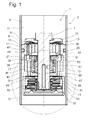
- the FIG. 1 shows a valve device 1 in a vibration damper 3 of any design.
- the vibration damper 3 comprises a filled with damping medium cylinder 5, in which a piston rod 7 is guided axially movable.
- a piston 9 On the piston rod 7, a piston 9 is fixed, the cylinder 5 in a piston rod side and a piston rod remote working space 11; 13 divided.
- the piston 9 has passageways 15; 17 for the passage of damping medium from one working space to the other.
- the passageways 15 are provided for the flow direction starting from the piston rod-side working space 11 to the piston rod remote working space 13.
- the passage channels 17 are available.
- Both passage channel groups 15; 17 are at their outlet openings of at least one valve body 19; 21 at least partially covered.
- a star-shaped disc spring 23 biases the valve disk 19 on an upper-side valve seat surface 25 of the piston 9.
- valve body 21 is pressed by a closing spring 27 against a lower-side valve seat surface 29.
- the passageways 17 with the valve disc 19 and the disc spring 23 form a first damping valve 31.
- a second damping valve 33 form the passageways 15 together with the valve body 21 and the closing spring 27, wherein the piston 9 for both damping valve 31; 33 forms the Dämpfventil emotions.
- the valve body 21 comprises a rigid valve disc 35, which is sealed at its inner diameter to a guide pin 37, formed by a piston rod pin, via a ring seal 39.
- the valve disc 35 connects to a guide sleeve 41.
- the valve body 21 slides over its guide sleeve 41 in a control chamber 43 which is formed by a cup-shaped control chamber housing 45 in which the closing spring 27 is arranged.
- the control chamber 43 is consequently bounded by the guide pin 37 holding the valve device 1, the control chamber housing 45 and the valve body 21.
- the pre-opening disk 47 has an opening 49 in an annular groove 51 of the valve body 21. At least one outflow opening 53 connects the annular groove 51 with the control chamber 43.
- the control chamber 43 has a flow connection 55 to a pressure chamber 57.
- the flow connection 55 is designed with a stepped profile.
- the longitudinal bore in the guide pin 37 is made significantly larger in terms of the lowest possible temperature influence.
- the pressure chamber 57 is separated by an axially displaceable separating piston 59 to a rear space 61, wherein both spaces 57; 61 and the separating piston 59 are arranged in a pressure chamber housing 63, which is also attached to the guide pin 37.
- the separating piston 59 is designed as an annular piston and slides axially displaceably on the guide pin 37.
- About the axially movable separating piston 59 of the pressure chamber 57 is volume variable, wherein the volumes of the pressure chamber 57 and the back space 61 change in opposite directions.
- the filled with damping medium rear space 61 is connected via at least one pressure equalization opening 65 with the piston rod remote working chamber 13, wherein the pressure compensation opening 65 is controlled by a check valve 67, the in Outflow direction from the rear space 61 opens.
- the check valve 67 is formed by at least one elastic disc 69, which is braced between the pressure chamber housing 63 and the control chamber housing 45.
- At least one spring 71 is disposed within the rear space 61, which biases the separating piston 59 in the direction of the control chamber 43.
- damping medium is displaced through the passageways 15 in the direction of the inlet throttle disk 47.
- a portion of the volume flow regardless of the position of the valve body 21 to the valve seat surface 29 by a Vorö Stammsquerites not shown, for. B. in the form of a notch in the valve seat surface 29, in the piston rod remote working space 13.
- the damping medium enters the pressure chamber 57, the volume of which increases against the spring force of the at least one spring 71.
- the pressure in the pressure chamber 57 With the axial displacement of the separating piston 59, the pressure in the pressure chamber 57 and thus also increases in the control chamber 43.
- the increased pressure level in the control chamber 43 causes an increasingly greater closing force on the valve body 21.
- the pressure in the control chamber 43 tends to close the valve body 21, but is the pressurized surface at the top of the inlet throttle disk 47 is larger than the annular pressurized surface of the valve body 21 with its guide sleeve 41 within the control chamber 43, so that the damping valve 33 assumes a limited opening position at a peak load.
- a piston rod retraction movement in the direction of the piston rod remote working chamber 13 generates via the passageways 17 on the first damping valve 31 a damping force.
- the damping medium via at least one connection channel 73 within a wall of the control chamber housing 45 to reach the passageways 17, so for the opposite flow direction to the control room 43. Die Damping force is not influenced by a control room.
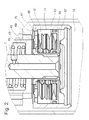
- the rear space 61 in the pressure chamber housing 63 is closed by at least one throttle cross section 75 (see FIG. Fig. 2 ) filled again. Due to the decrease in pressure in the pressure chamber 57 and the control chamber 43 in the direction of movement reversal of the piston rod 7, the valve body 21 has taken its closed position.
- FIGS. 3 and 4 show a functionally identical valve device 1 as for Fig. 1 ,
- the difference consists in the spring set 71 in the rear space 61.
- Deviating no wave spring or disc springs are used, but simple flat discs of spring steel, like the Fig. 4 shows are systematically stratified.
- an internally centered spacer 77 with a comparatively small width is combined with a disk 79 which has at least one recess 81 on the outside.
- This disc 81 is followed by an externally centered spacer 83, on which a disc 85 rests with a recess 87 on the inner diameter.
- This basic pattern can be followed by several disk packages until the back space 61 is filled.
- the entire stack of disks can be compressed axially.
- a big advantage of this variant is the part price for the used discs.
- the damping medium in the rear space 61 can via the recesses 81; 87 reach the pressure equalization holes 65.
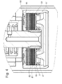
- FIG. 5 a further possibility for a force acting on the pressure chamber 57 biasing force is shown.
- no separating piston is used, but a gas cushion 89, the z. B. is chambered in a flexible sheath 91.
- This valve device 1 follows the operating principle of the Fig. 1 and 2 , Instead of the separating piston movement, the gas cushion 89 is compressed in a piston rod movement in the direction of the piston rod-side working space 11.
- the advantage is, inter alia, that you do not need filling the back space via a check valve 67. There are no friction losses, since the flexible sheath 91 is not exposed to frictional contact.
- the valve device according to the invention is not limited to the arrangement on a piston rod 7, but can also be used as a cylinder 5 of the vibration damper 3 stationary assembly, for. B. as a so-called bottom valve or as mounted outside of the cylinder 5 element.
Landscapes
- Engineering & Computer Science (AREA)
- General Engineering & Computer Science (AREA)
- Physics & Mathematics (AREA)
- Fluid Mechanics (AREA)
- Mechanical Engineering (AREA)
- Fluid-Damping Devices (AREA)
- Axle Suspensions And Sidecars For Cycles (AREA)
Applications Claiming Priority (1)
| Application Number | Priority Date | Filing Date | Title |
|---|---|---|---|
| DE200810042637 DE102008042637B4 (de) | 2008-10-07 | 2008-10-07 | Ventileinrichtung mit amplitudenabhängiger Dämpfkraft |
Publications (2)
| Publication Number | Publication Date |
|---|---|
| EP2175161A2 true EP2175161A2 (fr) | 2010-04-14 |
| EP2175161A3 EP2175161A3 (fr) | 2014-08-06 |
Family
ID=41509087
Family Applications (1)
| Application Number | Title | Priority Date | Filing Date |
|---|---|---|---|
| EP09171929.4A Withdrawn EP2175161A3 (fr) | 2008-10-07 | 2009-10-01 | Dispositif de soupape doté d'une force d'amortissement dépendant de l'amplitude |
Country Status (2)
| Country | Link |
|---|---|
| EP (1) | EP2175161A3 (fr) |
| DE (1) | DE102008042637B4 (fr) |
Cited By (2)
| Publication number | Priority date | Publication date | Assignee | Title |
|---|---|---|---|---|
| WO2017220252A1 (fr) * | 2016-06-20 | 2017-12-28 | Zf Friedrichshafen Ag | Ensemble soupape de fond sélectif en fréquence |
| CN109154352A (zh) * | 2016-05-23 | 2019-01-04 | 蒂森克虏伯比尔斯坦有限公司 | 用于机动车辆的、具有旁通控制阀的频率选择性减震器 |
Families Citing this family (2)
| Publication number | Priority date | Publication date | Assignee | Title |
|---|---|---|---|---|
| DE102014214654B4 (de) * | 2014-07-25 | 2023-07-20 | Volkswagen Aktiengesellschaft | Ventil-Kolben-Anordnung für einen Schwingungsdämpfer |
| DE102020210282A1 (de) * | 2020-08-13 | 2022-02-17 | Zf Friedrichshafen Ag | Dämpfventileinrichtung mit einem Vorstufen- und einem Hauptstufenventil |
Citations (2)
| Publication number | Priority date | Publication date | Assignee | Title |
|---|---|---|---|---|
| DE3100910C2 (fr) | 1981-01-14 | 1989-09-07 | Fichtel & Sachs Ag, 8720 Schweinfurt, De | |
| WO2003040586A1 (fr) | 2001-11-06 | 2003-05-15 | Koni B.V. | Amortisseur de chocs avec amortissement en fonction de frequence |
Family Cites Families (4)
| Publication number | Priority date | Publication date | Assignee | Title |
|---|---|---|---|---|
| DE3348176C2 (en) * | 1983-09-24 | 1988-02-04 | August Bilstein Gmbh & Co Kg, 5828 Ennepetal, De | Adjustable shock absorber, in particular for motor vehicles |
| JP2694465B2 (ja) * | 1989-05-19 | 1997-12-24 | トキコ株式会社 | 油圧緩衝器 |
| FR2651553B1 (fr) * | 1989-09-06 | 1991-12-13 | Sirven Jacques | Valve pour fluide hydraulique et amortisseur comportant une telle valve. |
| JP5090034B2 (ja) * | 2006-09-07 | 2012-12-05 | カヤバ工業株式会社 | 緩衝器のバルブ構造 |
-
2008
- 2008-10-07 DE DE200810042637 patent/DE102008042637B4/de not_active Expired - Fee Related
-
2009
- 2009-10-01 EP EP09171929.4A patent/EP2175161A3/fr not_active Withdrawn
Patent Citations (2)
| Publication number | Priority date | Publication date | Assignee | Title |
|---|---|---|---|---|
| DE3100910C2 (fr) | 1981-01-14 | 1989-09-07 | Fichtel & Sachs Ag, 8720 Schweinfurt, De | |
| WO2003040586A1 (fr) | 2001-11-06 | 2003-05-15 | Koni B.V. | Amortisseur de chocs avec amortissement en fonction de frequence |
Cited By (4)
| Publication number | Priority date | Publication date | Assignee | Title |
|---|---|---|---|---|
| CN109154352A (zh) * | 2016-05-23 | 2019-01-04 | 蒂森克虏伯比尔斯坦有限公司 | 用于机动车辆的、具有旁通控制阀的频率选择性减震器 |
| CN109154352B (zh) * | 2016-05-23 | 2020-12-04 | 蒂森克虏伯比尔斯坦有限公司 | 用于机动车辆的、具有旁通控制阀的频率选择性减震器 |
| US11002333B2 (en) | 2016-05-23 | 2021-05-11 | Thyssenkrupp Bilstein Gmbh | Frequency-selective vibration damper for motor vehicles with a bypass control valve |
| WO2017220252A1 (fr) * | 2016-06-20 | 2017-12-28 | Zf Friedrichshafen Ag | Ensemble soupape de fond sélectif en fréquence |
Also Published As
| Publication number | Publication date |
|---|---|
| EP2175161A3 (fr) | 2014-08-06 |
| DE102008042637A1 (de) | 2010-04-08 |
| DE102008042637B4 (de) | 2010-06-10 |
Similar Documents
| Publication | Publication Date | Title |
|---|---|---|
| DE10101177C1 (de) | Teleskop-Schwingungsdämpfer | |
| EP1767810B1 (fr) | Dispositf de valve d'amortisseur ayant une évolution progressive de la force d'amortissement | |
| EP1775495A2 (fr) | Amortisseur de vibrations avec force d'amortissement réglable | |
| WO2016066314A1 (fr) | Procédé pour faire fonctionner un amortisseur de vibrations réglable destiné à des véhicules automobiles | |
| DE19901639B4 (de) | Druckabhängig reagierendes Ventil, insbesondere für einen Schwingungsdämpfer | |
| DE1505478A1 (de) | Stufenlos verstellbarer Stossdaempfer,insbesondere fuer Kraftfahrzeuge | |
| DE102011075909A1 (de) | Verstellbare Dämpfventileinrichtung für einen Schwingungsdämpfer | |
| DE112019000908T5 (de) | Dämpfungs-ventil und stoss-dämpfer | |
| EP2366915A2 (fr) | Amortisseur d'oscillations doté d'une force d'amortissement en fonction de la levée | |
| DE102016218375A1 (de) | Dämpfventil für einen Schwingungsdämpfer | |
| EP1923595B1 (fr) | Amortisseur d'oscillations doté d'une force d'amortissement dépendant de l'amplitude | |
| EP2108858A2 (fr) | Amortisseur d'oscillations doté d'une force d'amortissement dépendant de l'amplitude | |
| EP2628974A2 (fr) | Dispositif de robinet de vapeur réglable pour un amortisseur dýoscillations | |
| DE1936858B2 (de) | Selbstpumpendes hydraulisches Federbein mit innerer Niveauregelung für Fahrzeuge | |
| DE102008042637B4 (de) | Ventileinrichtung mit amplitudenabhängiger Dämpfkraft | |
| WO2018103982A1 (fr) | Butée de fin de course pour amortisseur de vibrations | |
| DE102008043564A1 (de) | Schwingungsdämpfer mit einstellbarer Dämpfkraft | |
| DE102007027813B4 (de) | Schwingungsdämpfer mit verstellbarem Dämpfventil | |
| DE10343875B4 (de) | Schwingungsdämpfer mit hubabhängiger Dämpfkraft | |
| DE19961963B4 (de) | Dämpfkrafteinrichtung mit veränderbarer Dämpfkraft | |
| EP2103836A2 (fr) | Amortisseur d'oscillations doté d'une force d'amortissement à amplitude sélective | |
| DE102008044081A1 (de) | Schwingungsdämpfer mit hubabhängiger Dämpfkraft | |
| EP1908984A2 (fr) | Amortisseur d'oscillations doté d'une force d'amortissement à amplitude sélective | |
| DE102010031144B4 (de) | Schwingungsdämpfer mit amplitudenabhängiger Dämpfkraft | |
| DE102007008621A1 (de) | Ventilbaugruppe |
Legal Events
| Date | Code | Title | Description |
|---|---|---|---|
| PUAI | Public reference made under article 153(3) epc to a published international application that has entered the european phase |
Free format text: ORIGINAL CODE: 0009012 |
|
| AK | Designated contracting states |
Kind code of ref document: A2 Designated state(s): AT BE BG CH CY CZ DE DK EE ES FI FR GB GR HR HU IE IS IT LI LT LU LV MC MK MT NL NO PL PT RO SE SI SK SM TR |
|
| PUAL | Search report despatched |
Free format text: ORIGINAL CODE: 0009013 |
|
| AK | Designated contracting states |
Kind code of ref document: A3 Designated state(s): AT BE BG CH CY CZ DE DK EE ES FI FR GB GR HR HU IE IS IT LI LT LU LV MC MK MT NL NO PL PT RO SE SI SK SM TR |
|
| RIC1 | Information provided on ipc code assigned before grant |
Ipc: F16F 9/512 20060101AFI20140630BHEP |
|
| 17P | Request for examination filed |
Effective date: 20150127 |
|
| RBV | Designated contracting states (corrected) |
Designated state(s): AT BE BG CH CY CZ DE DK EE ES FI FR GB GR HR HU IE IS IT LI LT LU LV MC MK MT NL NO PL PT RO SE SI SK SM TR |
|
| STAA | Information on the status of an ep patent application or granted ep patent |
Free format text: STATUS: THE APPLICATION IS DEEMED TO BE WITHDRAWN |
|
| 18D | Application deemed to be withdrawn |
Effective date: 20160503 |