EP2175263B1 - Capteur de marchandises à vapeur et procédé de détermination de marchandises à vapeur - Google Patents
Capteur de marchandises à vapeur et procédé de détermination de marchandises à vapeur Download PDFInfo
- Publication number
- EP2175263B1 EP2175263B1 EP20090172523 EP09172523A EP2175263B1 EP 2175263 B1 EP2175263 B1 EP 2175263B1 EP 20090172523 EP20090172523 EP 20090172523 EP 09172523 A EP09172523 A EP 09172523A EP 2175263 B1 EP2175263 B1 EP 2175263B1
- Authority
- EP
- European Patent Office
- Prior art keywords
- vapour
- droplets
- sensor element
- quality sensor
- temperature
- Prior art date
- Legal status (The legal status is an assumption and is not a legal conclusion. Google has not performed a legal analysis and makes no representation as to the accuracy of the status listed.)
- Not-in-force
Links
- 238000000034 method Methods 0.000 title claims description 7
- 238000010438 heat treatment Methods 0.000 claims description 27
- 239000000919 ceramic Substances 0.000 claims description 21
- 239000000463 material Substances 0.000 claims description 17
- PNEYBMLMFCGWSK-UHFFFAOYSA-N Alumina Chemical compound [O-2].[O-2].[O-2].[Al+3].[Al+3] PNEYBMLMFCGWSK-UHFFFAOYSA-N 0.000 claims description 7
- 238000009529 body temperature measurement Methods 0.000 claims description 6
- PXHVJJICTQNCMI-UHFFFAOYSA-N Nickel Chemical compound [Ni] PXHVJJICTQNCMI-UHFFFAOYSA-N 0.000 claims description 4
- KDLHZDBZIXYQEI-UHFFFAOYSA-N Palladium Chemical compound [Pd] KDLHZDBZIXYQEI-UHFFFAOYSA-N 0.000 claims description 4
- RVTZCBVAJQQJTK-UHFFFAOYSA-N oxygen(2-);zirconium(4+) Chemical compound [O-2].[O-2].[Zr+4] RVTZCBVAJQQJTK-UHFFFAOYSA-N 0.000 claims description 4
- BASFCYQUMIYNBI-UHFFFAOYSA-N platinum Chemical compound [Pt] BASFCYQUMIYNBI-UHFFFAOYSA-N 0.000 claims description 4
- 229910001928 zirconium oxide Inorganic materials 0.000 claims description 4
- 238000010292 electrical insulation Methods 0.000 claims description 3
- 229910052581 Si3N4 Inorganic materials 0.000 claims description 2
- VYPSYNLAJGMNEJ-UHFFFAOYSA-N Silicium dioxide Chemical compound O=[Si]=O VYPSYNLAJGMNEJ-UHFFFAOYSA-N 0.000 claims description 2
- 229910052759 nickel Inorganic materials 0.000 claims description 2
- 229910052763 palladium Inorganic materials 0.000 claims description 2
- 229910052697 platinum Inorganic materials 0.000 claims description 2
- 150000004760 silicates Chemical class 0.000 claims description 2
- HBMJWWWQQXIZIP-UHFFFAOYSA-N silicon carbide Chemical compound [Si+]#[C-] HBMJWWWQQXIZIP-UHFFFAOYSA-N 0.000 claims description 2
- 229910010271 silicon carbide Inorganic materials 0.000 claims description 2
- HQVNEWCFYHHQES-UHFFFAOYSA-N silicon nitride Chemical compound N12[Si]34N5[Si]62N3[Si]51N64 HQVNEWCFYHHQES-UHFFFAOYSA-N 0.000 claims description 2
- WFKWXMTUELFFGS-UHFFFAOYSA-N tungsten Chemical compound [W] WFKWXMTUELFFGS-UHFFFAOYSA-N 0.000 claims description 2
- 229910052721 tungsten Inorganic materials 0.000 claims description 2
- 239000010937 tungsten Substances 0.000 claims description 2
- 230000008016 vaporization Effects 0.000 claims 2
- 229910017083 AlN Inorganic materials 0.000 claims 1
- PIGFYZPCRLYGLF-UHFFFAOYSA-N Aluminum nitride Chemical compound [Al]#N PIGFYZPCRLYGLF-UHFFFAOYSA-N 0.000 claims 1
- 238000009834 vaporization Methods 0.000 claims 1
- 239000010410 layer Substances 0.000 description 50
- XLYOFNOQVPJJNP-UHFFFAOYSA-N water Substances O XLYOFNOQVPJJNP-UHFFFAOYSA-N 0.000 description 10
- 238000005259 measurement Methods 0.000 description 9
- 238000001704 evaporation Methods 0.000 description 8
- 230000001681 protective effect Effects 0.000 description 8
- 238000001514 detection method Methods 0.000 description 7
- 230000008020 evaporation Effects 0.000 description 6
- 238000009413 insulation Methods 0.000 description 6
- 238000010276 construction Methods 0.000 description 5
- MCMNRKCIXSYSNV-UHFFFAOYSA-N Zirconium dioxide Chemical compound O=[Zr]=O MCMNRKCIXSYSNV-UHFFFAOYSA-N 0.000 description 4
- 238000001816 cooling Methods 0.000 description 4
- 239000007789 gas Substances 0.000 description 4
- 239000012071 phase Substances 0.000 description 4
- 238000005516 engineering process Methods 0.000 description 3
- 239000004020 conductor Substances 0.000 description 2
- 239000012530 fluid Substances 0.000 description 2
- 239000012808 vapor phase Substances 0.000 description 2
- BPQQTUXANYXVAA-UHFFFAOYSA-N Orthosilicate Chemical compound [O-][Si]([O-])([O-])[O-] BPQQTUXANYXVAA-UHFFFAOYSA-N 0.000 description 1
- 229910010293 ceramic material Inorganic materials 0.000 description 1
- 238000006243 chemical reaction Methods 0.000 description 1
- 238000002485 combustion reaction Methods 0.000 description 1
- PMHQVHHXPFUNSP-UHFFFAOYSA-M copper(1+);methylsulfanylmethane;bromide Chemical compound Br[Cu].CSC PMHQVHHXPFUNSP-UHFFFAOYSA-M 0.000 description 1
- 230000001419 dependent effect Effects 0.000 description 1
- 238000013461 design Methods 0.000 description 1
- KZHJGOXRZJKJNY-UHFFFAOYSA-N dioxosilane;oxo(oxoalumanyloxy)alumane Chemical compound O=[Si]=O.O=[Si]=O.O=[Al]O[Al]=O.O=[Al]O[Al]=O.O=[Al]O[Al]=O KZHJGOXRZJKJNY-UHFFFAOYSA-N 0.000 description 1
- 230000000694 effects Effects 0.000 description 1
- 238000003197 gene knockdown Methods 0.000 description 1
- 239000010416 ion conductor Substances 0.000 description 1
- 235000000396 iron Nutrition 0.000 description 1
- 239000002346 layers by function Substances 0.000 description 1
- 238000004519 manufacturing process Methods 0.000 description 1
- 238000012544 monitoring process Methods 0.000 description 1
- 229910052863 mullite Inorganic materials 0.000 description 1
- 238000013021 overheating Methods 0.000 description 1
- TWNQGVIAIRXVLR-UHFFFAOYSA-N oxo(oxoalumanyloxy)alumane Chemical compound O=[Al]O[Al]=O TWNQGVIAIRXVLR-UHFFFAOYSA-N 0.000 description 1
- 239000002245 particle Substances 0.000 description 1
- 230000001012 protector Effects 0.000 description 1
- 238000012372 quality testing Methods 0.000 description 1
- 230000035945 sensitivity Effects 0.000 description 1
- 229910002076 stabilized zirconia Inorganic materials 0.000 description 1
- 230000000930 thermomechanical effect Effects 0.000 description 1
- 239000002918 waste heat Substances 0.000 description 1
Images



Classifications
-
- G—PHYSICS
- G01—MEASURING; TESTING
- G01N—INVESTIGATING OR ANALYSING MATERIALS BY DETERMINING THEIR CHEMICAL OR PHYSICAL PROPERTIES
- G01N25/00—Investigating or analyzing materials by the use of thermal means
- G01N25/56—Investigating or analyzing materials by the use of thermal means by investigating moisture content
- G01N25/58—Investigating or analyzing materials by the use of thermal means by investigating moisture content by measuring changes of properties of the material due to heat, cold or expansion
- G01N25/60—Investigating or analyzing materials by the use of thermal means by investigating moisture content by measuring changes of properties of the material due to heat, cold or expansion for determining the wetness of steam
Definitions
- the present invention relates to a steam quality sensor according to the manner defined in more detail in claim 1.
- a method for determining the vapor quality according to claim 9 is the subject of the present invention.
- the senor must withstand the operational requirements of 40 bar and 400 ° C.
- Hiding water droplets in front of the turbine via impactors is not desirable because such an impactor stage would create additional back pressure in the system.
- the DE 10 2006 015 384 A1 describes a device for temperature sensing in a fluid, in particular a particulate exhaust fluid of a combustion process in an automotive engine, and thus a vehicle-mounted temperature sensor.
- the DE 10 2006 032 549 A1 describes a gas or particle sensor in which the sensitive area is arranged within an opening. A heating element may also be provided. However, detection of droplets in the vapor is not described.
- the EP 1 422 137 A1 discloses an aircraft icing sensor.
- the EP 0 285 918 A2 discloses a steam meter for power plants.
- the steam quality sensor according to the invention according to claim 1, with which the method according to claim 9 also according to the invention can be carried out has the advantage over the prior art that it detects droplets present in the steam.
- it is suitable by its construction, even under the extreme conditions in automotive technology, for example, in relation to the high temperatures and pressures in the supercritical steam of steam turbochargers, to be used reliably.
- the steam quality sensor ensures both a very good detection of droplets in a vapor and in particular has a simple structure and at the same time can be used as a temperature sensor.
- the steam quality sensor of the present invention can be used both for example in the start phase of the steam turbine for steam quality testing and in later continuous operation as a temperature sensor
- Heating the ceramic sensor element to a temperature slightly above the steam temperature has been found to provide excellent detection of droplets possibly contained in the vapor.
- the subject of the present invention is therefore a steam quality sensor for the detection of droplets in a vapor phase containing a ceramic sensor element with at least one temperature measuring device and at least one heating device, which is characterized in that the ceramic sensor element can be heated by the heating device above the steam temperature of the droplets to be detected .
- the ceramic sensor element may have a layer structure.
- the sensor element may preferably be formed rod-shaped with a round or rectangular cross section, wherein a base layer of an insulating or conductive ceramic base material, another layer with Heating device and at least one layer with temperature measuring device are provided. If an insulating ceramic is used as the base material, then a layer sequence with insulation layer, heating layer, base layer, temperature measuring device and upper insulation layer can be used for the vapor quality sensor according to the present invention.
- the lower and upper insulation layers serve to protect against falsification of the measurement signal by water vapor. Under certain circumstances can be dispensed with these insulation layers.
- a protective tube can also be provided for mechanical protection.
- the temperature measuring device may be located on the surface of the sensor element.
- the ceramic sensor element may consist of a high-temperature-stable and hydrothermally resistant material.
- the material is preferably selected from the group of silicates, aluminum oxide, silicon carbide, quartz glass, silicon nitride, aluminum nitride, zirconium oxide and LTCC.
- Mullite or codierite can be used as examples of suitable silicate materials.
- the heating device can be electrically insulated from the ceramic sensor element.
- the electrical insulation can be achieved for example by enclosing the heater with alumina.
- yttrium-stabilized zirconium oxide is an ionic conductor at temperatures above about 300 ° C.
- the material of the heater may be selected from the group tungsten, platinum, palladium, nickel, stabilized zirconia and ceramics.
- the material of the heating device can thus preferably be adapted to the production process.
- the steam quality sensor according to the invention comprises at least two temperature measuring devices, one of which is exposed to the vapor with droplets and at least one other is exposed to the vapor without droplets.
- the spatially different arrangement of the temperature measuring devices can be done either on the front and back of the sensor element or on the same side of the sensor element.
- the droplets can be masked out by suitable thermowell arrangements for at least one temperature measuring device.
- the temperature measuring device can be designed as a resistance thermometer or as a thermocouple.
- a zirconia sensor material can be used as a temperature sensor by suitably attached near-surface electrodes.
- an instantaneous evaporation of impinging droplets from the steam is advantageously achieved.
- the evaporation of the impinging droplets result in a decrease in temperature, which can be determined with the temperature measuring device. If in a start-up phase of a steam turbine or a steam turbocharger, for example, to obtain energy from the exhaust gas of a motor vehicle, the steam is still mixed with a plurality of droplets, the temperature measuring device will not record a constant temperature signal but the signal will knock down by the respective cooling and show a so-called "fidgeting".
- the temperature signal of the temperature measuring device will always be made more constant and, upon reaching the operating situation, will be converted into a relatively constant signal.
- a detection of the number of droplets in the vapor and an end of the droplet loading of the vapor can be achieved.
- the information depth of the signal can be further increased, since this time-varying signal includes a statement about the coupled thermal mass and thus also on the coupled water on the sensor.
- Another object of the present invention is the use of a steam quality sensor according to at least one of claims 1 to 8 or a method according to claim 9 in a motor vehicle.
- a steam quality sensor according to the invention can be used, for example, directly in front of a steam turbine, where it is of interest at this point mainly for the start-up phase of the system, that is to say when droplets are still entrained with the steam. He acts as a sensor for "droplet end detection". In the operating condition reached, no more water droplets are expected in the superheated steam.
- the sensor can also be used advantageously in or after the evaporator before overheating. Here, it can provide usable measurement data throughout the operating period, which with the characteristic curve and the operating parameters of superheating are helpful for the system control / monitoring of the overall system steam turbocharger.
- FIG. 1 schematically four different possible layer sequences for the construction of a steam quality sensor according to the invention are shown.
- a layer structure is shown, in which a base layer of a conductive material 2 separated by a respective insulating layer 5, an overlying layer 3 is provided with a temperature measuring device and an underlying layer 4 is provided with a heating device.
- upper and lower insulation layers 5 are used as the outer protector in front of the water vapor environment.
- the sensor element can be protected from a falsification of the measurement result by the water vapor.
- FIG. 1b a construction of a vapor quality sensor according to the invention is shown, which comprises two base layers of conductive material, such as yttrium-doped zirconia.
- a layer provided with a heating device On the upper base layer 2 , also separated by an insulating layer 5 from the base layer 2 , a layer with a temperature measuring device 3 is applied. The upper layer with the temperature measuring device 3 is again separated by a covering insulating layer 5 from the gas space.
- Figure 1c a possible construction of a sensor according to the invention with two ceramic, conductive base layers 2 and two layers with temperature measuring devices 3a and 3b is shown.
- the layer with the heating device 4 for heating the sensor element to a temperature above the steam temperature is in this construction in the middle between the two base layers 2 and is separated therefrom by an insulating layer 5 in each case.
- an upper and a lower insulating layer 5 are arranged on the respective layer with the temperature measuring device 3a and 3b .
- Figure 1d becomes a similar structure as in the previous one Figure 1c ).
- the base layers of insulating base material 6, whereby a simplified structure without insulating layers for the functional layers 4 , 3a and 3b is made possible.
- the shown final insulating layers 5 can be dispensed with a suitable protective tube geometry on these outer insulating layers 5 , which also for the other structures shown FIGS. 1a) to 1c ) applies. In all the structures shown, it is envisaged that droplets only hit the sensor from above.
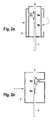
- FIG. 2 schematically two examples of protective tube geometries are shown with a functional character in an embodiment of a Dampfgütesensors invention with two temperature measuring devices.
- the rod-shaped sensors 1 each have two measuring points 8 .
- the upper measuring point for the temperature measurement 8a stands by the placement of the recesses in the protective tubes 7 directly under the influence of the droplets in the water vapor.
- the thermal mass can be reduced in the region of the measuring points.
- the reduced thermal mass of the measuring points 8a and 8b is indicated by the thin regions of the rod-shaped sensor.
- the embodiments of the steam quality sensor according to the invention shown may be advantageous a difference measurement between the measuring point with impinging droplets and the measuring point are made without impinging droplets, whereby the accuracy of the measurement can be increased.
- this type of flow control through the protective tube 7 large droplets can be hidden to protect the sensor element. If these are to be included, the flow in the case of FIG. 2b ) come directly from the right (direct flow).
- the protective tube 7 in FIG. 2a ) is unsuitable for this last case because large droplets can not follow the flow guide.
- FIG. 3 show two embodiments of the steam quality sensor of the present invention with thermally reduced mass in an exploded view and in a plan view of the measuring point of a temperature measuring device.
- FIG. 3a shows a three-layer structure of a sensor according to the invention with an upper and a lower insulating layer 5 and a ceramic base layer 2.
- a temperature measuring device 3 At the top of the ceramic base layer 2 is a temperature measuring device 3 with a measuring point.
- 8 Recesses and cutouts for redirecting the thermal mass allow a more accurate measurement because an impinging and re-evaporating droplet must cool less mass. As a result, the overall sensitivity of the measuring point is increased.
- a heating device (not shown) which heats the entire sensor element to a temperature above the steam temperature and thus achieves the evaporation of the impinging droplets.
- the two insulation layers 5 have in the region of the measuring point 8 in each case recesses 9 , which allow access for droplets to the measuring point.
- FIG. 3b shows a simplified, two-layer structure in which the upper insulating layer compared to the previous one FIG. 3a ) is omitted.
- Figure 3c shows in a top view the area of the measuring point 8 in the base layer 2.
- the temperature measuring device 3 is provided on a separate area by recesses and material reduction by cutouts in the layer. In this way, the thermal mass is reduced in the measuring point area, so that the cooling can be determined more accurately by the evaporation of the impinging droplets.
- thermocouple 3 is provided in both figures 4a) and 4b).
Landscapes
- Physics & Mathematics (AREA)
- Health & Medical Sciences (AREA)
- Life Sciences & Earth Sciences (AREA)
- Chemical & Material Sciences (AREA)
- Analytical Chemistry (AREA)
- Biochemistry (AREA)
- General Health & Medical Sciences (AREA)
- General Physics & Mathematics (AREA)
- Immunology (AREA)
- Pathology (AREA)
- Investigating Or Analyzing Materials Using Thermal Means (AREA)
- Measuring Temperature Or Quantity Of Heat (AREA)
Claims (10)
- Capteur de qualité de vapeur pour détecter des gouttelettes dans une phase vapeur, et contenant un élément de capteur céramique (1), avec un premier dispositif de mesure de température (3) et au moins un dispositif de chauffage (4), l'élément de capteur céramique pouvant être chauffé par le dispositif de chauffage au-dessus de la température d'évaporation des gouttelettes à détecter, afin d'obtenir une évaporation immédiate hors de la vapeur de gouttelettes formées, une détection du nombre de gouttelettes dans la vapeur et la fin d'une charge en gouttelettes de la vapeur pouvant être obtenues au moyen du signal de température, caractérisé en ce que le capteur de qualité de vapeur comprend au moins deux dispositifs de mesure de température, les dispositifs de mesure de température étant disposés soit sur le côté avant et le côté arrière de l'élément de capteur soit du même côté de l'élément de capteur, de sorte que l'un soit exposé à la vapeur contenant des gouttelettes et au moins un autre soit exposé à la vapeur sans gouttelettes.
- Capteur de qualité de vapeur selon la revendication 1, caractérisé en ce que l'élément de capteur céramique présente une structure stratifiée.
- Capteur de qualité de vapeur selon la revendication 1 ou 2, caractérisé en ce que le dispositif de mesure de température se trouve à la surface de l'élément de capteur.
- Capteur de qualité de vapeur selon au moins l'une quelconque des revendications précédentes, caractérisé en ce que l'élément de capteur céramique se compose d'un matériau stable à haute température et hydrothermiquement résistant.
- Capteur de qualité de vapeur selon la revendication 4, caractérisé en ce que le matériau est choisi parmi le groupe des silicates, de l'oxyde d'aluminium, du carbure de silicium, du verre de quartz, du nitrure de silicium, du nitrure d'aluminium, de l'oxyde de zirconium et du LTCC.
- Capteur de qualité de vapeur selon au moins l'une quelconque des revendications précédentes, caractérisé en ce que le dispositif de chauffage est isolé électriquement par rapport à l'élément de capteur céramique et l'isolation électrique est obtenue en entourant le dispositif de chauffage avec de l'oxyde d'aluminium.
- Capteur de qualité de vapeur selon au moins l'une quelconque des revendications précédentes, caractérisé en ce que le matériau du dispositif de chauffage est choisi parmi le groupe du tungstène, du platine, du palladium, du nickel, de l'oxyde de zirconium stabilisé et de la céramique.
- Capteur de qualité de vapeur selon au moins l'une quelconque des revendications précédentes, caractérisé en ce que le dispositif de mesure de température est réalisé sous forme de thermomètre à résistance ou sous forme de thermoélément.
- Procédé de détection de gouttelettes dans une vapeur, caractérisé par les étapes suivantes :a) fourniture d'un capteur de qualité de vapeur selon l'une quelconque des revendications 1 à 8,b) chauffage de l'élément de capteur par le dispositif de chauffage à une température au-dessus de la température d'évaporation, éventuellementc) modulation de la puissance de chauffage du dispositif de chauffage en fonction du temps etd) détermination de la réduction de température provoquée par l'évaporation des gouttelettes formées.
- Utilisation d'un capteur de qualité de vapeur selon au moins l'une quelconque des revendications 1 à 8, ou d'un procédé selon la revendication 9, dans un véhicule automobile ou une centrale.
Applications Claiming Priority (1)
| Application Number | Priority Date | Filing Date | Title |
|---|---|---|---|
| DE200810042750 DE102008042750A1 (de) | 2008-10-10 | 2008-10-10 | Dampfgütesensor und Verfahren zur Dampfgütebestimmung |
Publications (3)
| Publication Number | Publication Date |
|---|---|
| EP2175263A2 EP2175263A2 (fr) | 2010-04-14 |
| EP2175263A3 EP2175263A3 (fr) | 2012-02-29 |
| EP2175263B1 true EP2175263B1 (fr) | 2015-04-29 |
Family
ID=41506464
Family Applications (1)
| Application Number | Title | Priority Date | Filing Date |
|---|---|---|---|
| EP20090172523 Not-in-force EP2175263B1 (fr) | 2008-10-10 | 2009-10-08 | Capteur de marchandises à vapeur et procédé de détermination de marchandises à vapeur |
Country Status (2)
| Country | Link |
|---|---|
| EP (1) | EP2175263B1 (fr) |
| DE (1) | DE102008042750A1 (fr) |
Families Citing this family (1)
| Publication number | Priority date | Publication date | Assignee | Title |
|---|---|---|---|---|
| CN105628874B (zh) * | 2015-12-28 | 2017-05-31 | 中国电子科技集团公司第四十九研究所 | 共烧结构的气体传感器及获得该传感器的方法 |
Family Cites Families (5)
| Publication number | Priority date | Publication date | Assignee | Title |
|---|---|---|---|---|
| US2970475A (en) * | 1956-10-08 | 1961-02-07 | Rosemount Eng Co Ltd | Gas temperature probe |
| EP0285918A3 (fr) * | 1987-04-06 | 1991-03-20 | Combustion Engineering, Inc. | Appareil pour la mesure de la qualité de la vapeur chauffé électriquement |
| US7014357B2 (en) * | 2002-11-19 | 2006-03-21 | Rosemount Aerospace Inc. | Thermal icing conditions detector |
| DE102006015384A1 (de) | 2006-04-03 | 2007-10-04 | Robert Bosch Gmbh | Vorrichtung zur Temperatursensierung in einem Fluid, insbesondere ein partikelbehaftetes Abgasfluid eines Verbrennungsvorgangs in einem Kraftfahrzeugmotor |
| DE102006032549A1 (de) | 2006-07-13 | 2008-01-17 | Robert Bosch Gmbh | Sensorelement eines Gassensors |
-
2008
- 2008-10-10 DE DE200810042750 patent/DE102008042750A1/de not_active Withdrawn
-
2009
- 2009-10-08 EP EP20090172523 patent/EP2175263B1/fr not_active Not-in-force
Also Published As
| Publication number | Publication date |
|---|---|
| DE102008042750A1 (de) | 2010-04-15 |
| EP2175263A2 (fr) | 2010-04-14 |
| EP2175263A3 (fr) | 2012-02-29 |
Similar Documents
| Publication | Publication Date | Title |
|---|---|---|
| DE102005029841B4 (de) | Mikromechanischer Drucksensor mit beheiztem Passivierungsmittel und Verfahren zu seiner Steuerung | |
| EP2502057B1 (fr) | Système et procédé d'analyse thermique | |
| EP1807842B1 (fr) | Procede et systeme d'echantillonnage pour produire un echantillon de l'atmosphere presente dans un recipient de surete du reacteur d'une installation nucleaire | |
| EP3105571B1 (fr) | Procédé et système de capteur de mesure de la concentration de gaz | |
| DE102015122673A1 (de) | Sensor zur Detektion elektrisch leitfähiger und/oder polarisierbarer Partikel, Sensorsystem, Verfahren zum Betreiben eines Sensors, Verfahren zur Herstellung eines derartigen Sensors und Verwendung eines derartigen Sensors | |
| EP2619539A1 (fr) | Agencement capteur | |
| EP3822624B1 (fr) | Élément capteur capacitif permettant de déterminer au moins une propriété d'un milieu fluide dans au moins une chambre de mesure et procédé pour fabriquer l'élément de capteur | |
| EP2175263B1 (fr) | Capteur de marchandises à vapeur et procédé de détermination de marchandises à vapeur | |
| DE102007031767A1 (de) | Beheizbarer Abgassensor mit verbesserter Erkennung von Wasser an einer Oberfläche des Abgassensors | |
| DE102008041809A1 (de) | Partikelsensor, Verfahren zu dessen Betrieb und Herstellung | |
| WO2009068455A2 (fr) | Mesure de la température environnante au moyen d'un élément de détection de gaz | |
| DE102009046457A1 (de) | Partikelsensor | |
| DE102016221369A1 (de) | Sensorelement zur Bestimmung von Partikeln in einem fluiden Medium | |
| DE102010002979A1 (de) | Verfahren und Vorrichtung zur Erfassung einer Eigenschaft eines fluiden Mediums | |
| EP3963300B1 (fr) | Calorimètre différentiel à haute sensibilité | |
| DE102004060103A1 (de) | Verfahren und Anordnung zur Erfassung brennbarer Gase, insbesondere zur Erfassung von Wasserstoff | |
| DE102020213786A1 (de) | Verfahren zum Bewerten eines Sensors, sowie entsprechendes Sensorsystem und Verfahren zum Betreiben des Sensorsystems | |
| DE102012209390A1 (de) | Sensorelement zur Erfassung mindestens einer Eigenschaft eines Messgases in einem Messgasraum | |
| DE102012217535A1 (de) | Gasturbine mit einem Wärmeflusssensor | |
| DE202008013264U1 (de) | Vergleichendes Messgerät zur Ermittlung der Wärmeleitfähigkeit von Dämmstoffen | |
| EP1459042A1 (fr) | Capteur thermique | |
| EP1801548B1 (fr) | Dispositif de mesure et/ou de monitorage de la température et/ou du débit d'un fluide | |
| DE102016200267A1 (de) | Mikromechanische Vorrichtung und Verfahren zum Detektieren eines Gases | |
| DE102014200170A1 (de) | Verfahren und Vorrichtung zur Erkennung einer Flutung eines Abgastrakts einer Brennkraftmaschine | |
| EP4356086B1 (fr) | Capteur, système de capteur et procédé de mesure de paramètres thermodynamiques d'un échantillon, et utilisation du capteur ou du système de capteur |
Legal Events
| Date | Code | Title | Description |
|---|---|---|---|
| PUAI | Public reference made under article 153(3) epc to a published international application that has entered the european phase |
Free format text: ORIGINAL CODE: 0009012 |
|
| AK | Designated contracting states |
Kind code of ref document: A2 Designated state(s): AT BE BG CH CY CZ DE DK EE ES FI FR GB GR HR HU IE IS IT LI LT LU LV MC MK MT NL NO PL PT RO SE SI SK SM TR |
|
| PUAL | Search report despatched |
Free format text: ORIGINAL CODE: 0009013 |
|
| AK | Designated contracting states |
Kind code of ref document: A3 Designated state(s): AT BE BG CH CY CZ DE DK EE ES FI FR GB GR HR HU IE IS IT LI LT LU LV MC MK MT NL NO PL PT RO SE SI SK SM TR |
|
| RIC1 | Information provided on ipc code assigned before grant |
Ipc: G01N 25/60 20060101AFI20120126BHEP |
|
| 17P | Request for examination filed |
Effective date: 20120829 |
|
| 17Q | First examination report despatched |
Effective date: 20121107 |
|
| GRAP | Despatch of communication of intention to grant a patent |
Free format text: ORIGINAL CODE: EPIDOSNIGR1 |
|
| INTG | Intention to grant announced |
Effective date: 20141209 |
|
| GRAS | Grant fee paid |
Free format text: ORIGINAL CODE: EPIDOSNIGR3 |
|
| GRAA | (expected) grant |
Free format text: ORIGINAL CODE: 0009210 |
|
| AK | Designated contracting states |
Kind code of ref document: B1 Designated state(s): AT BE BG CH CY CZ DE DK EE ES FI FR GB GR HR HU IE IS IT LI LT LU LV MC MK MT NL NO PL PT RO SE SI SK SM TR |
|
| REG | Reference to a national code |
Ref country code: GB Ref legal event code: FG4D Free format text: NOT ENGLISH |
|
| REG | Reference to a national code |
Ref country code: CH Ref legal event code: EP |
|
| REG | Reference to a national code |
Ref country code: AT Ref legal event code: REF Ref document number: 724699 Country of ref document: AT Kind code of ref document: T Effective date: 20150515 |
|
| REG | Reference to a national code |
Ref country code: IE Ref legal event code: FG4D Free format text: LANGUAGE OF EP DOCUMENT: GERMAN |
|
| REG | Reference to a national code |
Ref country code: DE Ref legal event code: R096 Ref document number: 502009010957 Country of ref document: DE Effective date: 20150611 |
|
| REG | Reference to a national code |
Ref country code: NL Ref legal event code: VDEP Effective date: 20150429 |
|
| REG | Reference to a national code |
Ref country code: LT Ref legal event code: MG4D |
|
| PG25 | Lapsed in a contracting state [announced via postgrant information from national office to epo] |
Ref country code: NL Free format text: LAPSE BECAUSE OF FAILURE TO SUBMIT A TRANSLATION OF THE DESCRIPTION OR TO PAY THE FEE WITHIN THE PRESCRIBED TIME-LIMIT Effective date: 20150429 |
|
| REG | Reference to a national code |
Ref country code: FR Ref legal event code: PLFP Year of fee payment: 7 |
|
| PG25 | Lapsed in a contracting state [announced via postgrant information from national office to epo] |
Ref country code: ES Free format text: LAPSE BECAUSE OF FAILURE TO SUBMIT A TRANSLATION OF THE DESCRIPTION OR TO PAY THE FEE WITHIN THE PRESCRIBED TIME-LIMIT Effective date: 20150429 Ref country code: FI Free format text: LAPSE BECAUSE OF FAILURE TO SUBMIT A TRANSLATION OF THE DESCRIPTION OR TO PAY THE FEE WITHIN THE PRESCRIBED TIME-LIMIT Effective date: 20150429 Ref country code: NO Free format text: LAPSE BECAUSE OF FAILURE TO SUBMIT A TRANSLATION OF THE DESCRIPTION OR TO PAY THE FEE WITHIN THE PRESCRIBED TIME-LIMIT Effective date: 20150729 Ref country code: HR Free format text: LAPSE BECAUSE OF FAILURE TO SUBMIT A TRANSLATION OF THE DESCRIPTION OR TO PAY THE FEE WITHIN THE PRESCRIBED TIME-LIMIT Effective date: 20150429 Ref country code: PT Free format text: LAPSE BECAUSE OF FAILURE TO SUBMIT A TRANSLATION OF THE DESCRIPTION OR TO PAY THE FEE WITHIN THE PRESCRIBED TIME-LIMIT Effective date: 20150831 Ref country code: LT Free format text: LAPSE BECAUSE OF FAILURE TO SUBMIT A TRANSLATION OF THE DESCRIPTION OR TO PAY THE FEE WITHIN THE PRESCRIBED TIME-LIMIT Effective date: 20150429 |
|
| PG25 | Lapsed in a contracting state [announced via postgrant information from national office to epo] |
Ref country code: IS Free format text: LAPSE BECAUSE OF FAILURE TO SUBMIT A TRANSLATION OF THE DESCRIPTION OR TO PAY THE FEE WITHIN THE PRESCRIBED TIME-LIMIT Effective date: 20150829 Ref country code: LV Free format text: LAPSE BECAUSE OF FAILURE TO SUBMIT A TRANSLATION OF THE DESCRIPTION OR TO PAY THE FEE WITHIN THE PRESCRIBED TIME-LIMIT Effective date: 20150429 Ref country code: GR Free format text: LAPSE BECAUSE OF FAILURE TO SUBMIT A TRANSLATION OF THE DESCRIPTION OR TO PAY THE FEE WITHIN THE PRESCRIBED TIME-LIMIT Effective date: 20150730 |
|
| PG25 | Lapsed in a contracting state [announced via postgrant information from national office to epo] |
Ref country code: EE Free format text: LAPSE BECAUSE OF FAILURE TO SUBMIT A TRANSLATION OF THE DESCRIPTION OR TO PAY THE FEE WITHIN THE PRESCRIBED TIME-LIMIT Effective date: 20150429 Ref country code: DK Free format text: LAPSE BECAUSE OF FAILURE TO SUBMIT A TRANSLATION OF THE DESCRIPTION OR TO PAY THE FEE WITHIN THE PRESCRIBED TIME-LIMIT Effective date: 20150429 |
|
| PGFP | Annual fee paid to national office [announced via postgrant information from national office to epo] |
Ref country code: IT Payment date: 20151026 Year of fee payment: 7 |
|
| REG | Reference to a national code |
Ref country code: DE Ref legal event code: R097 Ref document number: 502009010957 Country of ref document: DE |
|
| PG25 | Lapsed in a contracting state [announced via postgrant information from national office to epo] |
Ref country code: RO Free format text: LAPSE BECAUSE OF NON-PAYMENT OF DUE FEES Effective date: 20150429 Ref country code: SK Free format text: LAPSE BECAUSE OF FAILURE TO SUBMIT A TRANSLATION OF THE DESCRIPTION OR TO PAY THE FEE WITHIN THE PRESCRIBED TIME-LIMIT Effective date: 20150429 Ref country code: PL Free format text: LAPSE BECAUSE OF FAILURE TO SUBMIT A TRANSLATION OF THE DESCRIPTION OR TO PAY THE FEE WITHIN THE PRESCRIBED TIME-LIMIT Effective date: 20150429 Ref country code: CZ Free format text: LAPSE BECAUSE OF FAILURE TO SUBMIT A TRANSLATION OF THE DESCRIPTION OR TO PAY THE FEE WITHIN THE PRESCRIBED TIME-LIMIT Effective date: 20150429 |
|
| PGFP | Annual fee paid to national office [announced via postgrant information from national office to epo] |
Ref country code: FR Payment date: 20151026 Year of fee payment: 7 |
|
| PLBE | No opposition filed within time limit |
Free format text: ORIGINAL CODE: 0009261 |
|
| STAA | Information on the status of an ep patent application or granted ep patent |
Free format text: STATUS: NO OPPOSITION FILED WITHIN TIME LIMIT |
|
| 26N | No opposition filed |
Effective date: 20160201 |
|
| REG | Reference to a national code |
Ref country code: DE Ref legal event code: R119 Ref document number: 502009010957 Country of ref document: DE |
|
| PG25 | Lapsed in a contracting state [announced via postgrant information from national office to epo] |
Ref country code: SI Free format text: LAPSE BECAUSE OF FAILURE TO SUBMIT A TRANSLATION OF THE DESCRIPTION OR TO PAY THE FEE WITHIN THE PRESCRIBED TIME-LIMIT Effective date: 20150429 Ref country code: LU Free format text: LAPSE BECAUSE OF FAILURE TO SUBMIT A TRANSLATION OF THE DESCRIPTION OR TO PAY THE FEE WITHIN THE PRESCRIBED TIME-LIMIT Effective date: 20151008 |
|
| REG | Reference to a national code |
Ref country code: CH Ref legal event code: PL |
|
| GBPC | Gb: european patent ceased through non-payment of renewal fee |
Effective date: 20151008 |
|
| PG25 | Lapsed in a contracting state [announced via postgrant information from national office to epo] |
Ref country code: MC Free format text: LAPSE BECAUSE OF FAILURE TO SUBMIT A TRANSLATION OF THE DESCRIPTION OR TO PAY THE FEE WITHIN THE PRESCRIBED TIME-LIMIT Effective date: 20150429 |
|
| REG | Reference to a national code |
Ref country code: IE Ref legal event code: MM4A |
|
| PG25 | Lapsed in a contracting state [announced via postgrant information from national office to epo] |
Ref country code: CH Free format text: LAPSE BECAUSE OF NON-PAYMENT OF DUE FEES Effective date: 20151031 Ref country code: DE Free format text: LAPSE BECAUSE OF NON-PAYMENT OF DUE FEES Effective date: 20160503 Ref country code: LI Free format text: LAPSE BECAUSE OF NON-PAYMENT OF DUE FEES Effective date: 20151031 Ref country code: GB Free format text: LAPSE BECAUSE OF NON-PAYMENT OF DUE FEES Effective date: 20151008 |
|
| PG25 | Lapsed in a contracting state [announced via postgrant information from national office to epo] |
Ref country code: IE Free format text: LAPSE BECAUSE OF NON-PAYMENT OF DUE FEES Effective date: 20151008 |
|
| REG | Reference to a national code |
Ref country code: AT Ref legal event code: MM01 Ref document number: 724699 Country of ref document: AT Kind code of ref document: T Effective date: 20151008 |
|
| PG25 | Lapsed in a contracting state [announced via postgrant information from national office to epo] |
Ref country code: AT Free format text: LAPSE BECAUSE OF NON-PAYMENT OF DUE FEES Effective date: 20151008 |
|
| PG25 | Lapsed in a contracting state [announced via postgrant information from national office to epo] |
Ref country code: SM Free format text: LAPSE BECAUSE OF FAILURE TO SUBMIT A TRANSLATION OF THE DESCRIPTION OR TO PAY THE FEE WITHIN THE PRESCRIBED TIME-LIMIT Effective date: 20150429 Ref country code: HU Free format text: LAPSE BECAUSE OF FAILURE TO SUBMIT A TRANSLATION OF THE DESCRIPTION OR TO PAY THE FEE WITHIN THE PRESCRIBED TIME-LIMIT; INVALID AB INITIO Effective date: 20091008 Ref country code: BG Free format text: LAPSE BECAUSE OF FAILURE TO SUBMIT A TRANSLATION OF THE DESCRIPTION OR TO PAY THE FEE WITHIN THE PRESCRIBED TIME-LIMIT Effective date: 20150429 |
|
| PG25 | Lapsed in a contracting state [announced via postgrant information from national office to epo] |
Ref country code: SE Free format text: LAPSE BECAUSE OF FAILURE TO SUBMIT A TRANSLATION OF THE DESCRIPTION OR TO PAY THE FEE WITHIN THE PRESCRIBED TIME-LIMIT Effective date: 20150429 Ref country code: CY Free format text: LAPSE BECAUSE OF FAILURE TO SUBMIT A TRANSLATION OF THE DESCRIPTION OR TO PAY THE FEE WITHIN THE PRESCRIBED TIME-LIMIT Effective date: 20150429 |
|
| REG | Reference to a national code |
Ref country code: FR Ref legal event code: ST Effective date: 20170630 |
|
| PG25 | Lapsed in a contracting state [announced via postgrant information from national office to epo] |
Ref country code: BE Free format text: LAPSE BECAUSE OF NON-PAYMENT OF DUE FEES Effective date: 20151031 Ref country code: FR Free format text: LAPSE BECAUSE OF NON-PAYMENT OF DUE FEES Effective date: 20161102 |
|
| PG25 | Lapsed in a contracting state [announced via postgrant information from national office to epo] |
Ref country code: TR Free format text: LAPSE BECAUSE OF FAILURE TO SUBMIT A TRANSLATION OF THE DESCRIPTION OR TO PAY THE FEE WITHIN THE PRESCRIBED TIME-LIMIT Effective date: 20150429 Ref country code: MT Free format text: LAPSE BECAUSE OF FAILURE TO SUBMIT A TRANSLATION OF THE DESCRIPTION OR TO PAY THE FEE WITHIN THE PRESCRIBED TIME-LIMIT Effective date: 20150429 |
|
| PG25 | Lapsed in a contracting state [announced via postgrant information from national office to epo] |
Ref country code: IT Free format text: LAPSE BECAUSE OF NON-PAYMENT OF DUE FEES Effective date: 20161008 |
|
| PG25 | Lapsed in a contracting state [announced via postgrant information from national office to epo] |
Ref country code: MK Free format text: LAPSE BECAUSE OF FAILURE TO SUBMIT A TRANSLATION OF THE DESCRIPTION OR TO PAY THE FEE WITHIN THE PRESCRIBED TIME-LIMIT Effective date: 20150429 |