EP2175468A2 - Interrupteur automatique bipolaire pour applications de basse tension - Google Patents
Interrupteur automatique bipolaire pour applications de basse tension Download PDFInfo
- Publication number
- EP2175468A2 EP2175468A2 EP09171337A EP09171337A EP2175468A2 EP 2175468 A2 EP2175468 A2 EP 2175468A2 EP 09171337 A EP09171337 A EP 09171337A EP 09171337 A EP09171337 A EP 09171337A EP 2175468 A2 EP2175468 A2 EP 2175468A2
- Authority
- EP
- European Patent Office
- Prior art keywords
- circuit breaker
- kinematic mechanism
- protection device
- closing
- contacts
- Prior art date
- Legal status (The legal status is an assumption and is not a legal conclusion. Google has not performed a legal analysis and makes no representation as to the accuracy of the status listed.)
- Withdrawn
Links
Images


Classifications
-
- H—ELECTRICITY
- H01—ELECTRIC ELEMENTS
- H01H—ELECTRIC SWITCHES; RELAYS; SELECTORS; EMERGENCY PROTECTIVE DEVICES
- H01H83/00—Protective switches, e.g. circuit-breaking switches, or protective relays operated by abnormal electrical conditions otherwise than solely by excess current
- H01H83/14—Protective switches, e.g. circuit-breaking switches, or protective relays operated by abnormal electrical conditions otherwise than solely by excess current operated by imbalance of two or more currents or voltages, e.g. for differential protection
- H01H83/144—Protective switches, e.g. circuit-breaking switches, or protective relays operated by abnormal electrical conditions otherwise than solely by excess current operated by imbalance of two or more currents or voltages, e.g. for differential protection with differential transformer
-
- H—ELECTRICITY
- H01—ELECTRIC ELEMENTS
- H01H—ELECTRIC SWITCHES; RELAYS; SELECTORS; EMERGENCY PROTECTIVE DEVICES
- H01H83/00—Protective switches, e.g. circuit-breaking switches, or protective relays operated by abnormal electrical conditions otherwise than solely by excess current
- H01H83/14—Protective switches, e.g. circuit-breaking switches, or protective relays operated by abnormal electrical conditions otherwise than solely by excess current operated by imbalance of two or more currents or voltages, e.g. for differential protection
- H01H83/142—Protective switches, e.g. circuit-breaking switches, or protective relays operated by abnormal electrical conditions otherwise than solely by excess current operated by imbalance of two or more currents or voltages, e.g. for differential protection with bimetal elements
Definitions
- the present invention relates to a low-voltage bipolar automatic circuit breaker, and in particular to a bipolar automatic circuit-breaker having both poles protected from faults (that is, there is no neutral pole or phase) and which exhibits a plurality of functionalities, while having a compact structure and reduced components.
- Low-voltage automatic circuit breakers are electrical devices of a known type. They are usually employed in electrical systems (for example, residential, industrial or commercial) in order to ensure the protection of the electrical systems and the safety of the users via the automatic opening of the circuit breaker itself, with consequent interruption of the power supply in response to failure situations.
- these faulty situations are short-circuits, overloads and earth leakages.
- one or more protection devices capable of discriminating between normal operational situations and failure situations are usually associated with the circuit breaker.
- Such devices usually comprise an actuator which, following a determined fault situation, intervenes on the kinematic mechanism of the circuit breaker, causing its automatic tripping and the opening of the contacts.
- Protection devices of the most common known type are the magnetothermic devices, which realize the protection from short-circuits and from overloads, and differential devices, which realize the earth leakage current protection.
- the protection devices consist, in some applications, of additional modules to be associated with the circuit breaker in order to realize a specific protection function.
- the circuit breaker and the protection devices are positioned within separate cases having a prearranged width of the modular type (one DIN module being equal to 17.5 mm). The cases are then associated and connected so as to obtain the required type of protection.
- the protection devices and the breaking part are contained within the same case, the latter usually has relatively bulky dimensions (for example, a width greater than two standard modules) in particular when both poles are protected and there is therefore no a neutral pole.
- the protection devices of the known type nevertheless require ad hoc components for their realization and dedicated mechanism for their coupling with the releasing kinematic mechanism, with consequent complications during the designing and realization phases of the circuit breaker and of the devices associated therewith.
- the main task of the present invention is to provide a low-voltage bipolar automatic circuit breaker that allows to overcome the described drawbacks.
- a low-voltage bipolar automatic circuit breaker which comprises a case made of insulating material that contains:
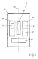
- a low-voltage bipolar automatic circuit breaker 1 comprises a case 10 made of an electrically insulating material, which contains a first pole 20 and a second pole 30, both of which are protected from fault conditions according to what will result from the description below.
- the rear part 11 of case 10 is suitably shaped and exhibits means for hooking to a DIN guide.
- the case 10 is arranged to allow cabling via the insertion of suitable cables or rods in suitable terminals.
- the front part of case 10 is suitable for being coupled to a cover, which is not illustrated in the figure, for the complete enclosure of the circuit breaker itself.
- the first pole 20 comprises a first contact 21 and a second contact 22 that are couplable/decouplable to each other
- the second pole 30 comprises a third contact 31 and a fourth contact (not illustrated in the figure, but equivalent overall with the second stationary contact 22) that are couplable/decouplable to each other.
- the second 22 and fourth contacts are stationary while contacts 21 and 31 are movable between an opening position, in which they are decoupled from the corresponding stationary contacts, and a closing position in which they are coupled with said stationary contacts.
- the circuit breaker further comprises a closing/opening kinematic mechanism 40, which is operatively coupled to said first and second poles 20, 30 in order to carry out the coupling/decoupling of said first and second contacts 21, 22 and of said third 31 and fourth contacts.
- the closing/opening kinematic mechanism 40 comprises levers that transmit the movement of the knob 42 operated by a user to the contacts for carrying out the opening or closing maneuver of the circuit breaker; furthermore, said levers realize the opening of the contacts in case of a failure situation in the electrical system associated with the circuit breaker 1.
- the closing/opening kinematic mechanism 40 preferably comprises means for holding the mobile contact in the closed position and means for releasing the kinematic mechanism, allowing the automatic opening of the circuit breaker 1.
- the closing/opening kinematic mechanism 40 comprises at least one pair of levers, for example, the hooking lever 43 and the tripping lever 41, which, when engaged to each other, hold the contacts in the closed position.
- the tripping lever 41 is disengaged from the hooking lever 43 via rotation around the center 418, releasing the kinematic mechanism and permitting the automatic opening operation according to a mechanism, which will be described in detail below.
- the circuit breaker according to the invention is in fact suitable for ensuring the protection of the electrical systems (for example, residential, industrial or commercial) and the safety of the users through the automatic opening of the circuit breaker itself, with consequent interruption of the power supply in response to a first, second or third failure situation.
- these faulty situations are short-circuits, overloads and earth leakages, respectively.
- both the first pole 20 and the second pole 30 of the circuit breaker 1 respectively comprise a first short-circuit protection device 50 and a second short-circuit protection device 55.
- Such short-circuit protection devices 50 and 55 are of the well known type and typically comprise a magnetic actuator constituted by a coil, a movable core, a stationary core, a blade or more generally, a pin and a spring, which realize the protection against short-circuits.
- the circuit breaker 1 further comprises a differential protection device 70, which is operatively associated with both poles 20 and 30; the protection device 70, which is also of a well known type and therefore not described in detail, is usually a differential actuator that realizes the protection from earth leakage currents and is typically constituted by a relay and by a toroidal core.
- the differential protection 70 detects the earth leakage current as an unbalance between the currents of the two poles or phases 20 and 30.
- device 70 triggers the release of the kinematic mechanism 40 and therefore the decoupling of the mobile contacts from the corresponding stationary contacts.
- the bipolar circuit breaker 1 comprises a single, unique overload protection device 60 that is operatively associated with the first pole 20 and is suitable for causing the tripping of the kinematic mechanism 40 and the decoupling of said first and third contacts 21, 31 from said second 22 and fourth contacts, respectively, upon detection of an overload fault condition.
- the protection devices 50 and 55 are suitable for causing the release of said kinematic mechanism 40 and the opening of said first and second contacts 21, 22 and of said third 31 and fourth contacts following a fault condition due to a short-circuit in the electrical system associated with the circuit breaker 1.
- the overload protection device 60 is constituted by a thermal actuator that comprises a bimetal.
- the first short-circuit protection device 50 and the overload protection device 60 are usually consolidated to each other and constitute a magnetothermic device. Furthermore, it needs to be specified that, while the protection device 60 is calibrated for intervening when there are overloads of an intensity that is not particularly high, which are present for long times, the devices 50 and 55, in addition to intervening for short-circuit failures, can also intervene in the presence of overloads of higher intensity that appear in very short times.
- the automatic circuit breaker 1 comprises coupling means that operatively connect the closing/opening kinematic mechanism 40 to the various protection devices 50, 55, 60 and 70.
- the mechanical pulses of the various protection devices 50, 55, 60 and 70 are transferred to the releasing kinematic mechanism via a single mechanism, simplifying the structure of the circuit breaker compared to the conventional solutions that need dedicated mechanisms for every protection device.
- an embodiment of the closing/opening kinematic mechanism 40 conveniently comprises a first tripping lever 41 suitable for releasing the same kinematic mechanism 40 by disengaging a third hooking lever 43, allowing the automatic opening of the contacts of the two poles 20 and 30.
- the coupling means comprise, for example, a first tripping shaft 81 which operatively connects said closing/opening kinematic mechanism 40 to said first and second short-circuit protection devices 50 and 55, to the overload protection device 60 and to the differential protection device 70.
- the coupling means further comprise a second intervention lever 82 that operatively connects the closing/opening kinematic mechanism 40 to the protection device 70.
- the first tripping shaft 81 and the second intervention lever 82 are operatively connected to said first tripping lever 41.
- the coupling means constitute the single mechanical interface, for example, via the first tripping shaft 81 and the second intervention lever 82, through which the mechanical pulse, generated by the various protection devices 50, 55, 60, 70 in the presence of a corresponding failure situation, is transmitted to the closing/opening kinematic mechanism 40, acting, for example, on the tripping lever 41.
- the closing/opening kinematic mechanism 40 is kept blocked in the closed position for the interaction of the third hooking lever 43 with the first tripping lever 41.
- one end of the lever 43 is engaged by a suitable projection into the body of the lever 41 as a result of which the counterclockwise rotation of the lever 43 (and the resulting release of the circuit breaker) is impeded.
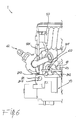
- the operation of automatic opening in the case of failure due to short-circuit is illustrated with reference to the figures 6 and 7 .
- the first protection device 50 and the second protection device 55 each comprise a blade 501 tied to the movable core. A portion of the blade 501 is positioned, under normal conditions (see figure 6 ), in proximity to a first extension 810 of the first tripping shaft 81.
- the protection device 50 or 55 intervenes, dragging inside the mobile core and consequently moving the blade 501 associated therewith (see fig. 7 , which shows the movement of the blade 501 to the right). Due to this movement, the blade 501 acts on the first extension 810 of the shaft 81, which rotates clockwise around its own pivot point 815.
- the shaft 81 exhibits a second extension 811 integral with it and suitably shaped. Due to the rotation of shaft 81, the second extension 811 interacts with the first tripping lever 41, causing the counterclockwise rotation around its own center of rotation 418.
- the tripping lever 41 disengages from the third hooking lever 43 allowing the movement and unblocking the closing/opening kinematic mechanism 40, which snaps into the open position, separating the mobile contacts 21 and 31 from the corresponding stationary contacts.
- the protection device 60 comprises a bimetal lamina suitable for bending because of overcurrents in the circuit. A portion of the lamina 60 is positioned, under normal conditions (see figure 6 ), in proximity to a third extension 812 of the first tripping shaft 81.
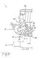
- the protection device 60 intervenes by flexure of the bimetal lamina (see fig. 8 , which shows the downward movement of the lamina 60). Because of this movement, the lamina 60 acts on the extension 812 of the shaft 81, which rotates clockwise around its own pivot point 815. As a result of this rotation, the second extension 811 of the shaft 81 interacts with the first tripping lever 41, causing the rotation and automatic opening of the contacts as previously described.
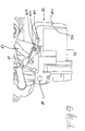
- the third protection device 70 comprises a piston 701 suitable for sliding because of an earth leakage of current and therefore of an unbalance of the current between the conductors associated with the two poles or phases 20 and 30.
- One end of the piston 701 is positioned, under normal conditions (see figure 9 ), in proximity to an arm 822 of a second intervention lever 82.
- the intervention lever 82 is suitably pivoted at point 820, can rotate with respect to it and it is kept in an idle position by suitable springs.
- the second intervention lever 82 further exhibits coupling means 821 with the first tripping lever 41.
- the means of intervention are constituted by a protuberance 821 suitable for interacting with a portion 410 of the tripping lever 41.
- the protection device 70 intervenes, causing the movement of piston 701 toward the outside of the relay (see fig. 10 , which shows the movement of the piston 701 to the right). Because of this movement, the piston 701 acts on the arm 822 of the lever 82, which rotates counterclockwise around its own pivot point 820. As a result of this rotation, the protuberance 821 of the intervention lever 82 interacts with the portion 410 of the first tripping lever 41, causing the counterclockwise rotation and automatic opening of the contacts as previously described.
- circuit breaker according to the invention can be realized in an extremely compact manner, by suitably positioning the various components within the case 10.
- the first pole 20 and the second pole 30 are conveniently positioned in a symmetric manner to the left and to the right of the longitudinal axis 100 of the circuit breaker 1, with respect to a front view of the same.
- the closing/opening kinematic mechanism 40 can therefore be advantageously centered with respect to said first and second poles 20, 30.
- the protection device 50 and the protection device 60 are overlapped and placed alongside the closing/opening kinematic mechanism 40.
- devices 50 and 60 for magnetothermic protection are usually grouped in a single body (and for this reason illustrated with a single functional block in figure 3 ) and positioned at the pole 20, in the front with respect to a front view of the circuit breaker 1.
- the protection device 55 is placed alongside the closing/opening kinematic mechanism 40 on the side opposite to the protection device 50.
- the protection device 70 is positioned transversally with regard to said longitudinal axis 100 and contiguous to said closing/opening kinematic mechanism 40, thus, being located, with respect to a front view of the circuit breaker, lower than the protection devices 50, 55, 60 and the kinematic mechanism 40.
- the resulting structure is exceedingly rational and compact.
- the arrangement of the components within case 10 is in fact substantially symmetric and allows to optimize the occupation of the spaces inside the case itself. Consequently, the dimensions of the circuit breaker can be held down; in particular, the width turns out to be equal to two DIN standard modules (35 mm), with substantial advantages from the modularity standpoint.
- the circuit breaker 1 accomplishes its predefined task, allowing to realize a high number of functions with a reduced number of components and with reduced costs.
- the bipolar circuit breaker 1 exhibits both the poles 20 and 30 protected from failures and in which the protection from overloads is obtained by utilizing a single bimetal, unlike what is known in the art in which each pole, where protected (and which, therefore, is not a neutral pole), provides the ad hoc use of a bimetal.
- the circuit breaker 1 thanks to its structure and functionality, allows to substantially simplify the realization of the mechanisms and of the couplings between the various components of the same.
- the coupling means via a single mechanism, allow to couple the protection devices with the releasing kinematic mechanism of the circuit breaker, further reducing the number of mechanical components, optimizing the space filled up within the case and at the same time having the complete range of protection (magnetic, thermic and differential) on both poles.
- the device according to the invention it is possible to consolidate a high number of functionalities in a single case, with resulting savings in terms of implementation and installation costs. Furthermore, the dimensions of the case, thanks to the extremely compact and rational arrangement of the components within it, are held down. In particular, it is possible to realize a circuit breaker of a width equal to two DIN standard modules and with both the poles protected, with substantial advantages in terms of modularity and rationality of installation.
Landscapes
- Engineering & Computer Science (AREA)
- Power Engineering (AREA)
- Breakers (AREA)
- Emergency Protection Circuit Devices (AREA)
Applications Claiming Priority (1)
| Application Number | Priority Date | Filing Date | Title |
|---|---|---|---|
| ITMI20080329 ITMI20080329U1 (it) | 2008-10-10 | 2008-10-10 | Interruttore automatico bipolare per applicazioni di bassa tensione |
Publications (2)
| Publication Number | Publication Date |
|---|---|
| EP2175468A2 true EP2175468A2 (fr) | 2010-04-14 |
| EP2175468A3 EP2175468A3 (fr) | 2013-09-04 |
Family
ID=41449864
Family Applications (1)
| Application Number | Title | Priority Date | Filing Date |
|---|---|---|---|
| EP09171337.0A Withdrawn EP2175468A3 (fr) | 2008-10-10 | 2009-09-25 | Interrupteur automatique bipolaire pour applications de basse tension |
Country Status (5)
| Country | Link |
|---|---|
| EP (1) | EP2175468A3 (fr) |
| CN (1) | CN101728127A (fr) |
| AU (1) | AU2009222597A1 (fr) |
| IT (1) | ITMI20080329U1 (fr) |
| RU (1) | RU2505881C2 (fr) |
Families Citing this family (3)
| Publication number | Priority date | Publication date | Assignee | Title |
|---|---|---|---|---|
| CN106783416B (zh) * | 2016-12-23 | 2018-02-09 | 台州市计量技术研究院 | 一种安全型漏电断路器及其使用方法 |
| CN109755078B (zh) * | 2017-11-07 | 2020-05-29 | 施耐德电气工业公司 | 低压配电装置及用于控制低压配电装置脱扣的方法 |
| CN207367899U (zh) * | 2017-11-07 | 2018-05-15 | 施耐德电气工业公司 | 能够检测预定状态的低压配电装置 |
Family Cites Families (11)
| Publication number | Priority date | Publication date | Assignee | Title |
|---|---|---|---|---|
| AT243354B (de) * | 1961-03-09 | 1965-11-10 | Busch Jaeger Duerener Metall | Installationsselbstschalter mit elektromagnetischer und thermischer Auslösung sowie mit Handabschaltung in Verbindung mit einer Fehlerschutzauslösung |
| DE1588113B2 (de) * | 1967-09-09 | 1976-07-29 | Condor-Werk Gebr. Frede Kg, Elektro- Und Maschinenfabrik, 4415 Westkirchen | Installations-vollschutzschalter |
| US3539867A (en) * | 1968-08-26 | 1970-11-10 | Federal Pacific Electric Co | Ground-fault protection systems |
| IT7721345U1 (it) * | 1977-05-17 | 1978-11-17 | Elettrocondutture | Dispositivo monoblocco per il sezionamento generale, il sezionamento parziale, la protezione contro le sovracorrenti e contro le tensioni di contatto di due o piu' linee uscenti dal punto dove la societa' distributrice consegna all'utente l'energia elettrica in bassa tensione |
| EP0103167B1 (fr) * | 1982-08-19 | 1987-11-11 | BROWN, BOVERI & CIE Aktiengesellschaft | Interrupteur avec déclenchement par un courant de fuite |
| JP2872950B2 (ja) * | 1995-11-01 | 1999-03-24 | 日東工業株式会社 | 漏電ブレーカ |
| CN2529375Y (zh) * | 2002-02-19 | 2003-01-01 | 周圣博 | 双极漏电断路器 |
| RU2259612C2 (ru) * | 2002-10-22 | 2005-08-27 | Закрытое Акционерное Общество "Электрические Низковольтные Аппараты И Системы" | Автоматический выключатель с двумя разрывами контактов |
| DE102004004840B4 (de) * | 2004-01-30 | 2006-05-11 | Siemens Ag | Schutzschaltvorrichtung mit Differenzstromauslöser |
| DE102004034859A1 (de) * | 2004-07-19 | 2006-02-16 | Siemens Ag | Schutzschaltgerät in Schmalbauweise |
| ITMI20072278A1 (it) * | 2007-12-04 | 2009-06-05 | Abb Spa | Interruttore automatico per applicazioni di bassa tensione. |
-
2008
- 2008-10-10 IT ITMI20080329 patent/ITMI20080329U1/it unknown
-
2009
- 2009-09-25 EP EP09171337.0A patent/EP2175468A3/fr not_active Withdrawn
- 2009-10-02 AU AU2009222597A patent/AU2009222597A1/en not_active Abandoned
- 2009-10-09 RU RU2009137575/07A patent/RU2505881C2/ru not_active IP Right Cessation
- 2009-10-10 CN CN200910179357A patent/CN101728127A/zh active Pending
Also Published As
| Publication number | Publication date |
|---|---|
| RU2505881C2 (ru) | 2014-01-27 |
| RU2009137575A (ru) | 2011-04-20 |
| EP2175468A3 (fr) | 2013-09-04 |
| ITMI20080329U1 (it) | 2010-04-11 |
| AU2009222597A1 (en) | 2010-04-29 |
| CN101728127A (zh) | 2010-06-09 |
Similar Documents
| Publication | Publication Date | Title |
|---|---|---|
| EP1939912B1 (fr) | Activation pour appareil de commutation | |
| EP0490332B1 (fr) | Disjoncteur | |
| CN101989518B (zh) | 一种相线加中线式剩余电流动作断路器 | |
| CN113035661B (zh) | 漏电断路器 | |
| US7843291B2 (en) | Integrated maglatch accessory | |
| EP2218088B1 (fr) | Commutateur automatique pour appareil basse tension | |
| EP2455961B1 (fr) | Dispositif de commutation électrique | |
| CN101170034A (zh) | 小型断路器 | |
| JPH02100230A (ja) | 遠隔操作式回路遮断器 | |
| EP2175468A2 (fr) | Interrupteur automatique bipolaire pour applications de basse tension | |
| US11804345B2 (en) | Low-voltage circuit breaker | |
| CN112735924A (zh) | 一种智能断路器 | |
| CN201629276U (zh) | 低压双极自动断路器 | |
| AU2022201971A1 (en) | Electrical protection device and electrical switchboard comprising such an electrical protection device | |
| AU2008333229B2 (en) | Automatic switch for low voltage application | |
| US3566326A (en) | Circuit breaker | |
| CN111276374A (zh) | 低压保护开关装置 | |
| EP1805776B1 (fr) | Mecanisme destine a un interrupteur de securite | |
| CN108899259A (zh) | 漏电保护断路器 | |
| AU2022201983A1 (en) | Electrical protection device and electrical switchboard comprising such an electrical protection device | |
| EP1017079B1 (fr) | Dispostif auxiliaire pour disjoncteurs | |
| RU2047237C1 (ru) | Автоматический выключатель | |
| KR101098930B1 (ko) | 전자식 배선용 차단기 | |
| CN101083184A (zh) | 选择性保护开关 | |
| JPH0475228A (ja) | 回路遮断器 |
Legal Events
| Date | Code | Title | Description |
|---|---|---|---|
| PUAI | Public reference made under article 153(3) epc to a published international application that has entered the european phase |
Free format text: ORIGINAL CODE: 0009012 |
|
| AK | Designated contracting states |
Kind code of ref document: A2 Designated state(s): AT BE BG CH CY CZ DE DK EE ES FI FR GB GR HR HU IE IS IT LI LT LU LV MC MK MT NL NO PL PT RO SE SI SK SM TR |
|
| AX | Request for extension of the european patent |
Extension state: AL BA RS |
|
| PUAL | Search report despatched |
Free format text: ORIGINAL CODE: 0009013 |
|
| AK | Designated contracting states |
Kind code of ref document: A3 Designated state(s): AT BE BG CH CY CZ DE DK EE ES FI FR GB GR HR HU IE IS IT LI LT LU LV MC MK MT NL NO PL PT RO SE SI SK SM TR |
|
| AX | Request for extension of the european patent |
Extension state: AL BA RS |
|
| RIC1 | Information provided on ipc code assigned before grant |
Ipc: H01H 83/14 20060101ALI20130729BHEP Ipc: H01H 83/22 20060101AFI20130729BHEP |
|
| STAA | Information on the status of an ep patent application or granted ep patent |
Free format text: STATUS: THE APPLICATION IS DEEMED TO BE WITHDRAWN |
|
| 18D | Application deemed to be withdrawn |
Effective date: 20140305 |